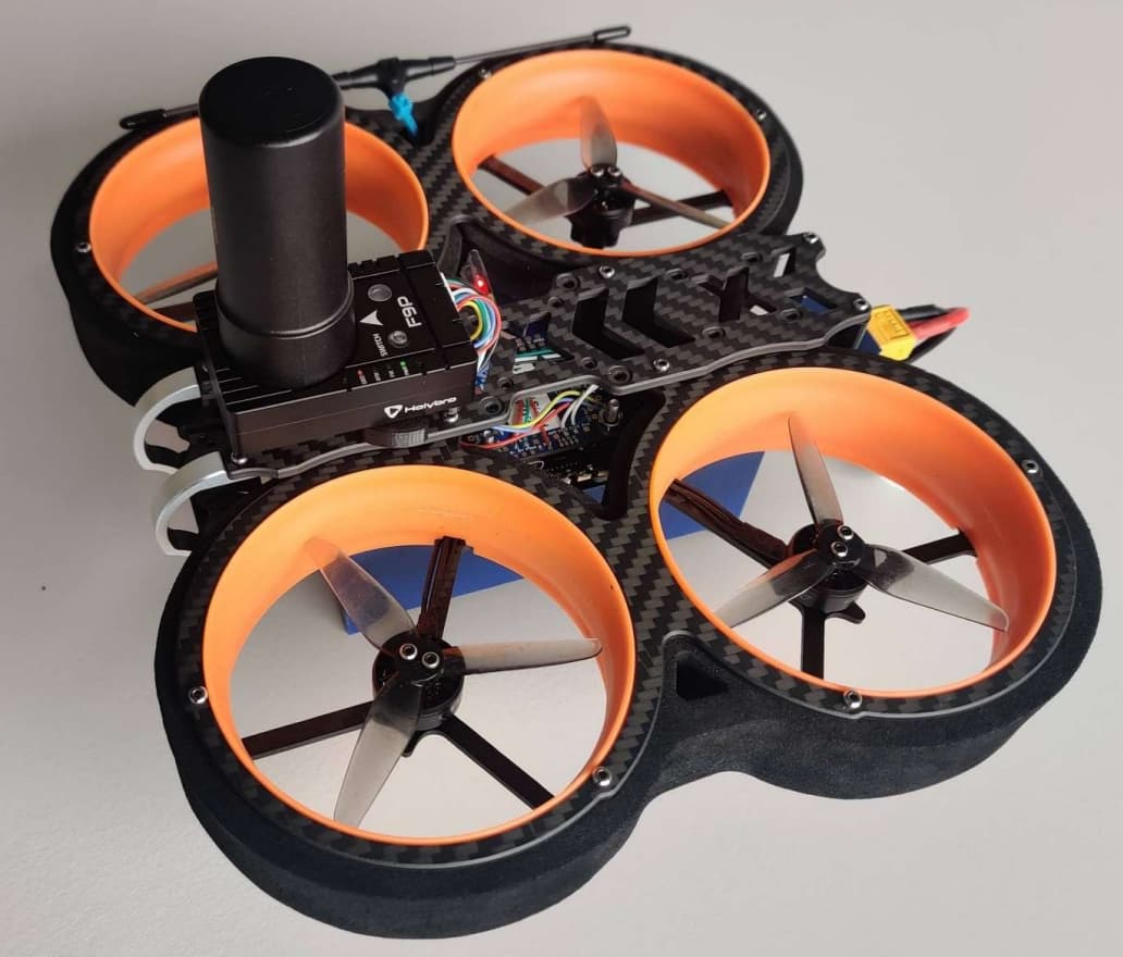
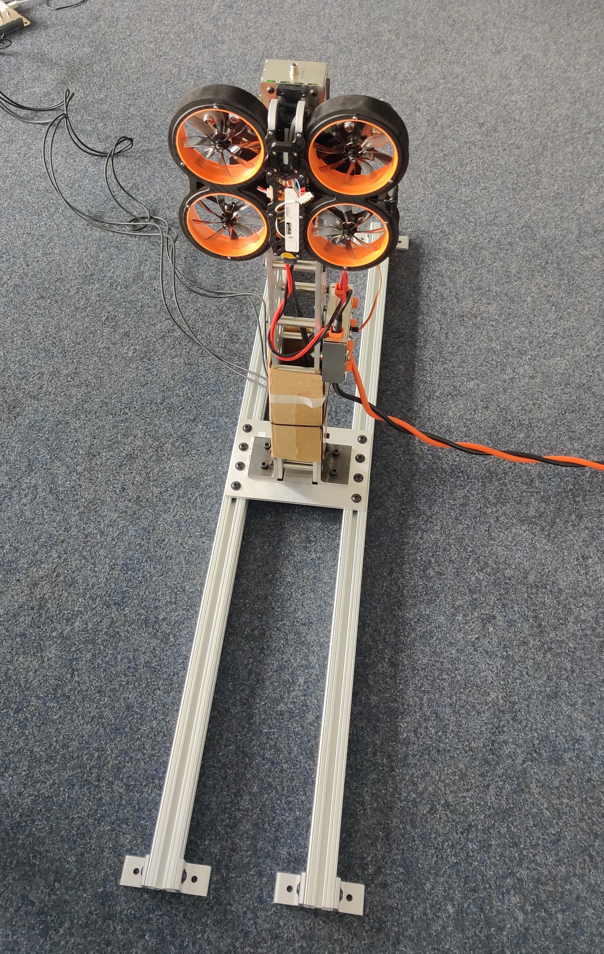
For illustrative purposes, we will use the small 3’’ multicopter depicted above, but the tuning sequence we developed at IAV GmbH will work on almost any other multicopter.
This method uses the latest available ArduPilot WebTools, some of the new features of ArduCopter 4.3 and above and best practices from the Ardupilot Community.
Sections 2.0 to 2.15 apply to all ArduPilot vehicles: ArduPlane, ArduRover, ArduBoat, ArduSub, ArduBlimp …
We will detail the firmware parameters to change, the sequence of how to change them, help you to find the value for each parameter, explain which test flights to conduct and the order in which to conduct them and help you document all your steps for traceability.
This applies industry-proven software configuration management (SCM) techniques to tuning an ArduCopter vehicle.
You will be able to tune multiple vehicles (think production line) using this method and still have individual traceability of each parameter change on each vehicle.
This post is divided into the following sections:
- Getting the hardware right
- Proper initial configuration
- First flight: Motor Thrust Hover and Harmonic Notch data collection
- Second flight: PID VTOL-Quiktune or manual tune
- Third flight: MagFit
- Fourth flight: PID VTOL-Quiktune or manual tune (optional)
- Fifth flight: Evaluate the aircraft tune - part 1
- Sixth flight: Evaluate the aircraft tune - part 2
- Autotune flight(s)
- Performance evaluation flight
- Windspeed Estimation flight(s)
- Baro Compensation flight(s)
- System Identification flights
- Productive configuration
- Position controller
- Precision land
- Guided operation without RC transmitter
- Conclusion
1. Getting the hardware right
1.1 Rules of thumb for hardware requirements
- Robust frame construction: A stable and rigid frame is crucial for stable and safe flight behavior. Carbon frames are recommended but not essential, and remember carbon is an electrical conductor.
- ESC telemetry: Use only ESCs that provide at least RPM telemetry. It simplifies Notch filter tuning and improves its response-time and accuracy.
- Vibration reduction: Vibrations reduce the efficiency, stability and lifespan of the drone. Propellers and motors are the source of most of the vibrations. All components must be securely fastened to minimize vibrations and avoid damage caused by vibrations. Stiff frames reduce vibrations.
- X and Y vibrations are caused by prop and/or motor imbalance - all propellers must be carefully balanced.
- Z vibrations are caused by the downwash of each blade hitting the arm and the forward traveling propeller hitting the oncoming air when moving.
- Protection of sensors from external disturbances:
- Vibration-damping mounting of the FC
- Separation of compass and high-current paths: To reduce electromagnetic interference, it is recommended to spatially separate the compass (likely integrated with GNSS receivers) from high-current paths and magnetic sources such as motors and power distribution systems/cables. Keep positive and negative wires close together using a gentile twist, brade or regularly spaced zip ties.
- Protection of barometer from airflow: The barometer must be protected from wind and airflow or turbulence generated by the propellers. A small piece of open-cell foam placed over the sensor acts as a low-pass filter, ensuring accurate altitude measurements.
- GNSS systems are likely to be affected by USB3 devices. Keep possible negative influences in mind while using USB3 components.
- Proper cable management: Cables and wires must be organized sensibly to prevent entanglement or damage during flight. It must be ensured that no cables hinder movable parts such as propellers or gimbal mechanisms, or are damaged by them. Flexible, silicone-coated cables for data transfer save weight and reduce vibration transmission. Weak connectors are prone to loosening under the influence of vibration.
- Weight distribution: An even weight distribution of the drone with the FC at the center of gravity improves stability and flight control. Components such as batteries, sensors, cameras, and other payloads must be positioned evenly to achieve uniform weight distribution and maximum fit between the geometric and physical center of gravity.
- Battery placement: The battery is often located in the center of the frame to ensure stability during flight. It must be ensured that the battery is rigidly mounted and secured to prevent slipping or unintentional disconnection during operation. Additionally, when properly attached, the battery acts as an inertial mass and helps damp vibrations. Beware of landing directly on the battery since most of the batteries do have a resistant shell.
- Voltage monitoring: to dynamically scale the PIDs and maintain stable flight in low battery conditions.
- Current monitoring: to compensate for the dynamic magnetic field caused by the high motor currents.
- FC Power supply: Must provide enough current for the flight controller, GNSS receivers and other payloads operating on 5V.
- Roll/Pitch/Yaw-Imbalance: When mounting the motors on the arms, especially on round arms, make sure that all motors and propellers are perfectly level so that the thrust produced is directed straight down. Misaligned motors will cause the multicopter to drift. Depending on which motors are misaligned and their direction of misalignment, the multicopter drifts laterally forward, backward, left, right, or axially around the Z-axis, and efficiency is reduced accordingly.
- Helical GNSS antennas: These kinds of antennas are the preferred choice for drones and their benefits justify the extra cost.
- STM32 H7 processor family: Flight controllers that use these processors, have enough processing power and memory to run ArduCopter firmware without restrictions.
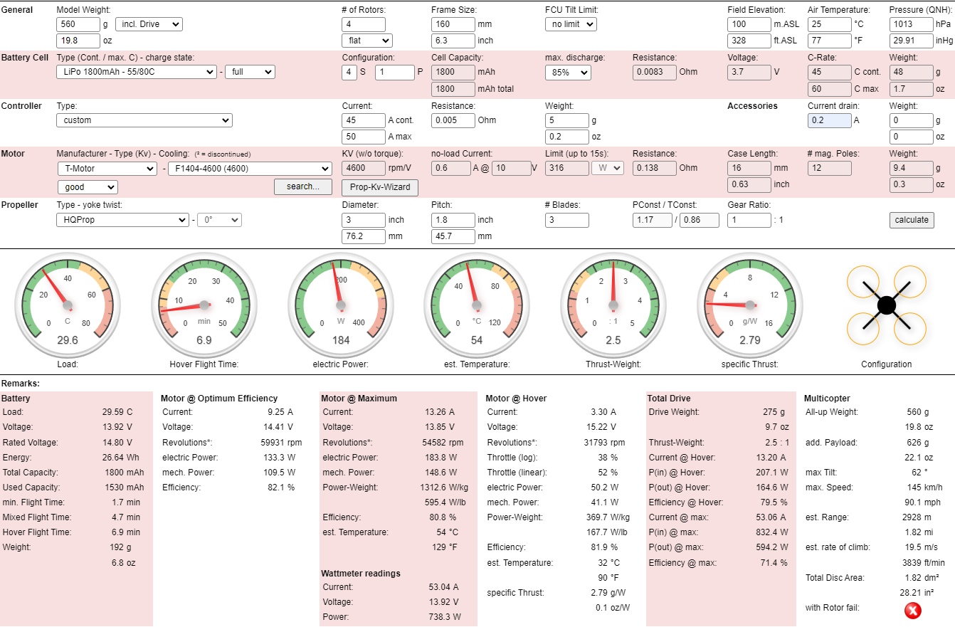
Use tools like ecalc for multirotor to find a suitable set of components to meet your needs.
1.2 Our vehicle
With these requirements in mind, and for our specific application, we have selected the following components:
| Type | Part |
|---|---|
| Frame | Diatone Taycan MX-C |
| Flight Controller | Matek H743 SLIM V3 |
| ESC | Mamba System F45_128k 4in1 ESC |
| Motors | 4x T-Motor 15507 3800kv |
| Propeller | 4x CineWhoop 3", 8-Blade |
| BEC with voltage/current monitor | Holybro PM02 V3 |
| Battery | SLS X-Cube 4S 1800mAh 40C/80C |
| GNSS receiver | Holybro H-RTK F9P Helical |
| SDCard | Any FAT32 or exFAT formated fast Micro-SDCard > 8 GiB |
| RC Receiver | TBS Crossfire Nano RX se |
| RC Transmitter | Radiomaster TX16S with EdgeTx and Yaapu scripts |
| Remote ID transmitter | Holybro Remote ID transmitter |
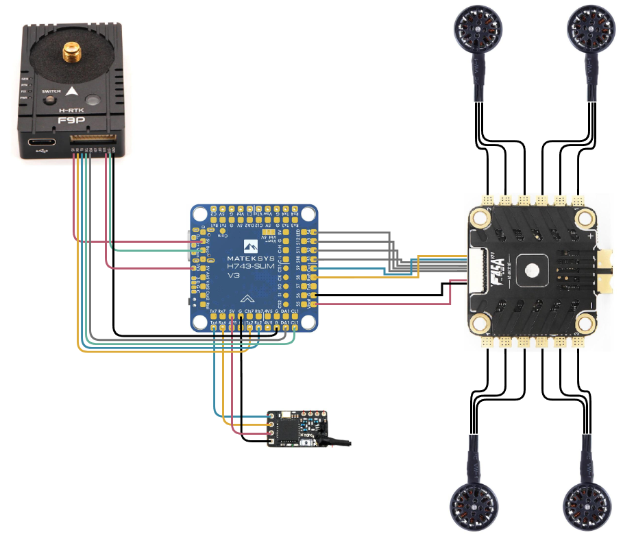
We connected the components as depicted below.
The figure excludes the LiPo battery and the PM02 BEC with a voltage/current monitor.
| Component | Flight controller connections |
|---|---|
| T-Motor F45 4in1 ESC V2 | G, G, Vbat, not Connected, S4, S3, S2, S1, Cur, Rx8 (SERIAL5) |
| Holybro PM02 V3 | not connected, G, Vbat2, Curr2, not Connected, not Connected |
| Holybro H-RTK F9P Helical | 5V, Tx2, Rx2, CL1, DA1, not connected, not connected, 3V3, Buzz, G |
| TBS Crossfire Nano RX se | G, 5V, Rx6, Tx6 |
2. Proper initial configuration
For reproducibility and quality purposes, we configure the vehicle with a well-defined sequence of intermediate parameter files.
Each file modifies just a small set of the over 1200 parameters on the flight controller.
By splitting the process into small manageable steps, we reduce the probability of making a mistake or missing a step and allow interleaving parameter changes with test flights.
Each intermediate parameter file is a text file, editable in any common text editor (excluding MS Word) like Notepad++, nano or code. It contains the official ArduPilot parameter documentation in the form of comments in the lines preceding the parameter. By using this you save the time of looking up the online documentation for each parameter.
It contains the reason why we changed the parameter in a comment on the same line as the parameter and is used to trace each parameter change to the reason for that parameter change.
Comments start with the ‘#’ character.
A small example with a single parameter is shown below:
# Arming with Rudder enable/disable
# Allow arm/disarm by rudder input. When enabled arming can be done with right rudder, disarming with left rudder.
# 0: Disabled
# 1: ArmingOnly
# 2: ArmOrDisarm
ARMING_RUDDER,0 # We find it safer to use only a switch to arm instead of through rudder inputs
If you are working with multiple vehicles, create a separate directory for each vehicle with a descriptive identifiable name. Copy the aprox. 40 intermediate parameter files into them. Edit the files to match the specific requirements of each vehicle. Now you have traceable documentation records for every parameter change on each of your vehicles.
If you are in the business of manufacturing multicopters and maintain high-quality standards that result in the production of multiple, nearly identical vehicles, you can reuse most intermediate parameter files across these vehicles. Only three intermediate parameter files: 03_imu_temperature_calibration_results.param, 11_mp_setup_mandatory_hardware.param and 23_inflight_magnetometer_fit_results.param are specific to each vehicle instance. All other intermediate parameter files can be used without modifications across all instances (or serial numbers) of the same product model.
2.1 List of the software used in this process
| Software | Version | Description |
|---|---|---|
| Mission Planner | latest beta | Ground control station (PC software) used for configuring and operating the vehicle |
| ArduPilot Methodic Configurator | latest | A clear ArduPilot configuration sequence |
| ArduCopter | 4.4.4 or 4.5.1 | Flight controller firmware |
| BLHeliSuite32 | 32.9.06 | PC software to flash and configure ESCs with BLHeli_32 ARM firmware |
| BLHeli_32 ARM | 32.8 | ESC firmware with Bidir Dshot support |
| EdgeTx companion | 2.9.2 | PC software for configuring and updating EdgeTX based RC transmitters |
| EdgeTx | 2.9.2 | Radiomaster TX16S firmware with touch screen support |
| Yaapu scripts | 2023-11-08 | Display vehicle telemetry on the Radiomaster TX16S |
| Simple text editor: Notepad++, nano or code | any | Allows editing plain text files without undesired text changes. Do not use microsoft word! |
| python | >= 3.8 | Python interpreter used to run automation scripts |
| MAVExplorer | latest | Analyze dataflash (.bin) log files |
| Scripted MagFit flightpath generation | latest | Lua script to generate a MagFit flight path |
| ecalc for multirotor | online | Finds a suitable set of components that meet your needs |
| ArduPilot Hardware Report | online | Provides an overview of connected hardware from a .bin log and visualization of sensor position offsets. |
| ArduPilot Filter Review Tool | online | Aid in configuring and validating the Harmonic Notch filters |
| ArduPilot Filter Analysis | online | Bode plot tool to give insight into gyro low-pass and notch filter attenuation and phase lag |
| ArduPilot PID Review Tool | online | Review PID tune in the frequency domain. Step response estimate is generated. |
| ArduPilot MAGFit in flight compass calibration | online | Do compass calibration using a flight log |
| Ardupilot Log Viewer | online | Log viewer, analyzer and plotter. Can also do MagFit |
| Add grid to image | online | Add a grid overlay to any image |
| SketchAndCalc | online | Calculate areas |
Always connect the vehicle battery before connecting the USB cable (if you are using one) between the PC and the flight controller.
Always disconnect the USB cable (if you are using one) between the PC and the flight controller before disconnecting the vehicle battery.
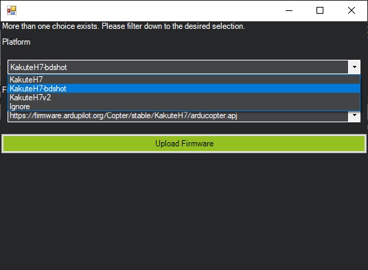
Start by downloading the latest Mission Planner ground control station software and the latest ArduPilot Methodic Configurator software both for your Microsoft Windows PC.
Use Mission Planner to flash the latest stable ArduCopter firmware for your flight controller.
2.2 Create the vehicles’s intermediate parameter files using a template
For this procedure follow these steps:
- Close Mission Planner, if it is open on the PC.
- Connect the flight controller to the PC via a USB cable and wait 7 seconds.
- Open ArduPilot Methodic Configurator, and connect it to the vehicle.
- Now using Option 1: Create a new vehicle configuration directory based on an existing template
- Select the template to use, select the destination directory, give it a name and press
Create vehicle directory from template
- Select the template to use, select the destination directory, give it a name and press
- On the component editor window, add all the details of the components of your system as we did in Section 1.2.
- Click the
Save data and start configurationbutton on the bottom - You now have a vehicle configuration directory with the name that you selected. But the files are just templates, you need to edit them in the next steps.
2.3 Configure IMU Temperature calibration using ArduPilot Methodic Configurator
For this procedure follow these steps:
- On ArduPilot Methodic Configurator select
04_board_orientation.paramon the Current intermediate parameter file: Combobox. - Read the Forum Blog: and Wiki: documentation by pressing on the blue URL links.
- Edit the
02_imu_temperature_calibration_setup.paramparameters’New ValueandChange Reasonusing the ArduPilot Methodic Configurator parameter editor and pressUpload selected params to FC, and advance to next file. - When ArduPilot Methodic Configurator asks you Do you want to provide a .bin log file and run the IMU temperature calibration using it? select
Noand close the program. - Power off the flight controller and remove the battery.
- Place the flight controller without battery in a freezer capable of reaching your vehicle’s minimum expected operation temperature (-18°C in our case).
- Once the flight controller is completely cooled down to its minimum expected operation temperature, take it out and power it. Do not move the flight controller for one or two hours.
- If you have a buzzer connected, you will hear a short periodic beep while the calibration is in progress. When the calibration is complete, a completion tune will play. If you have notification LEDs on your flight controller they will cyclically flash red, blue and green while calibrating. If you do not have a buzzer connected nor notification LEDs, monitor the
INS_TCALn_ENABLEparameters. On completion, theINS_TCALn_ENABLEparameters will change to 1 (enable) for each calibrated IMU. - Power it off, and remove the micro SDCard
- Copy the latest
.binlog file in the micro SDcard from/APM/LOGSto your PC - Insert the micro SDcard back into the flight controller
- Connect a USB cable to the FC and open ArduPilot Methodic Configurator. It will ask you again Do you want to provide a .bin log file and run the IMU temperature calibration using it? Select
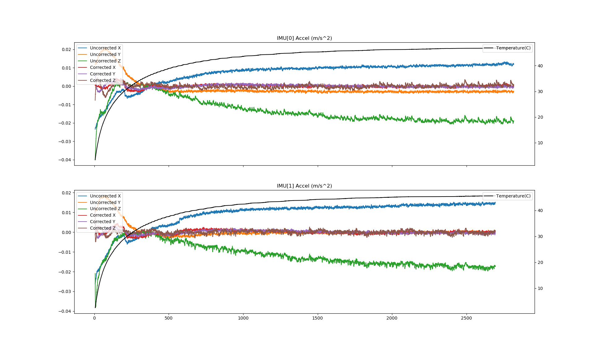
Yesand point it to the.binfile that you just downloaded. - Wait until finished It can take 10 Minutes or more look at the produced graphs they are also automatically saved to disk on the vehicle directory
- Press
Upload selected params to FC, and advance to next file.
The graphic below depicts the accelerometer drift versus time and the board temperature versus time. The temperature curve, depicted in black, is logarithmic as expected. The other curves are smooth, proving that the flight controller was not moved in the process and the calibration is valid. As can be seen, before the calibration temperature changes caused a big change in accelerometer/gyro drift. After the calibration, temperature changes will cause no significant accelerometer/gyro drift changes.
2.4 Completely assemble the vehicle
The vehicle must be completely assembled, with all cables connected, but WITHOUT propellers attached.
2.5 Configure flight controller orientation
Follow mounting the autopilot documentation to determine the correct value of the AHRS_ORIENTATION parameter.
2.5.1 Use ArduPilot Methodic Configurator to edit the parameter file and upload it to the flight controller
- The parameter file for this particular step is
04_board_orientation.paramother steps will use other parameter files - On ArduPilot Methodic Configurator select
04_board_orientation.paramon the Current intermediate parameter file: Combobox. - Read the documentation links inside the
04_board_orientation.param documentation - Add or Delete parameters if necessary, using the respective GUI buttons
- Edit the parameters’
New ValueandChange Reasonto suit your requirements - Press
Upload selected params to FC, and advance to next filebutton.
2.6 Configure the RC receiver
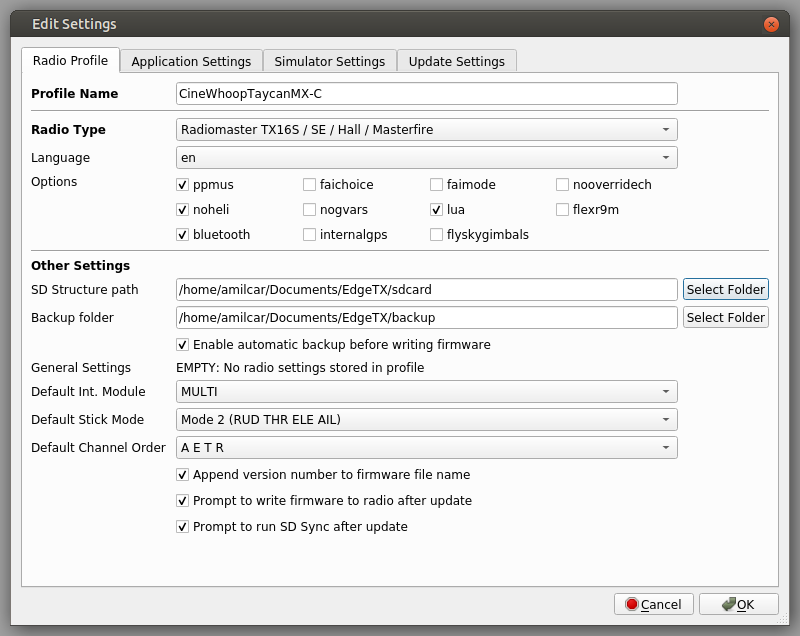
In our setup, we use EdgeTX firmware on the RC transmitter.
Download and install EdgeTX Companion to your PC. Start it and configure it as depicted below.
After that, use a micro SDcard to update the firmware on the Radiomaster TX16S and copy the yaapu scripts to the /WIDGETS/yaapu directory on the micro SDcard.
Once the RC transmitter is running EdgeTx you can load the TaycanMX-C.etx.bin (3.6 KB remove the .bin filename extension first) into EdgeTX companion and upload it to the radio.
Or simply copy only the settings that you require, EdgeTX companion is very flexible.
In our setup, we used an advanced RC receiver that cannot be fully configured using Mission Planner’s SETUP >> Mandatory Hardware >> Radio Calibration menu.
Repeat the steps from section 2.5.1 to edit and upload the 05_remote_controller.param file
After that test the RC failsafe
2.7 Configure telemetry
The RC transmitter we used has a big color display where telemetry data is displayed, nevertheless, we use telemetry data for real-time flight monitoring with Mission Planner or QGroundControl.
Repeat the steps from section 2.5.1 to edit and upload the 06_telemetry.param file
Once this is operating we no longer need the USB connection to the vehicle. We can now use the telemetry connection instead.
2.8 Configure the ESC
In our setup, we used a Bi-directional Dshot ESC that cannot be fully configured using Mission Planner’s SETUP >> Mandatory Hardware >> Servo Output menu.
Repeat the steps from section 2.5.1 to edit and upload the 07_esc.param file
The step above configured ESC communication pass-thru.
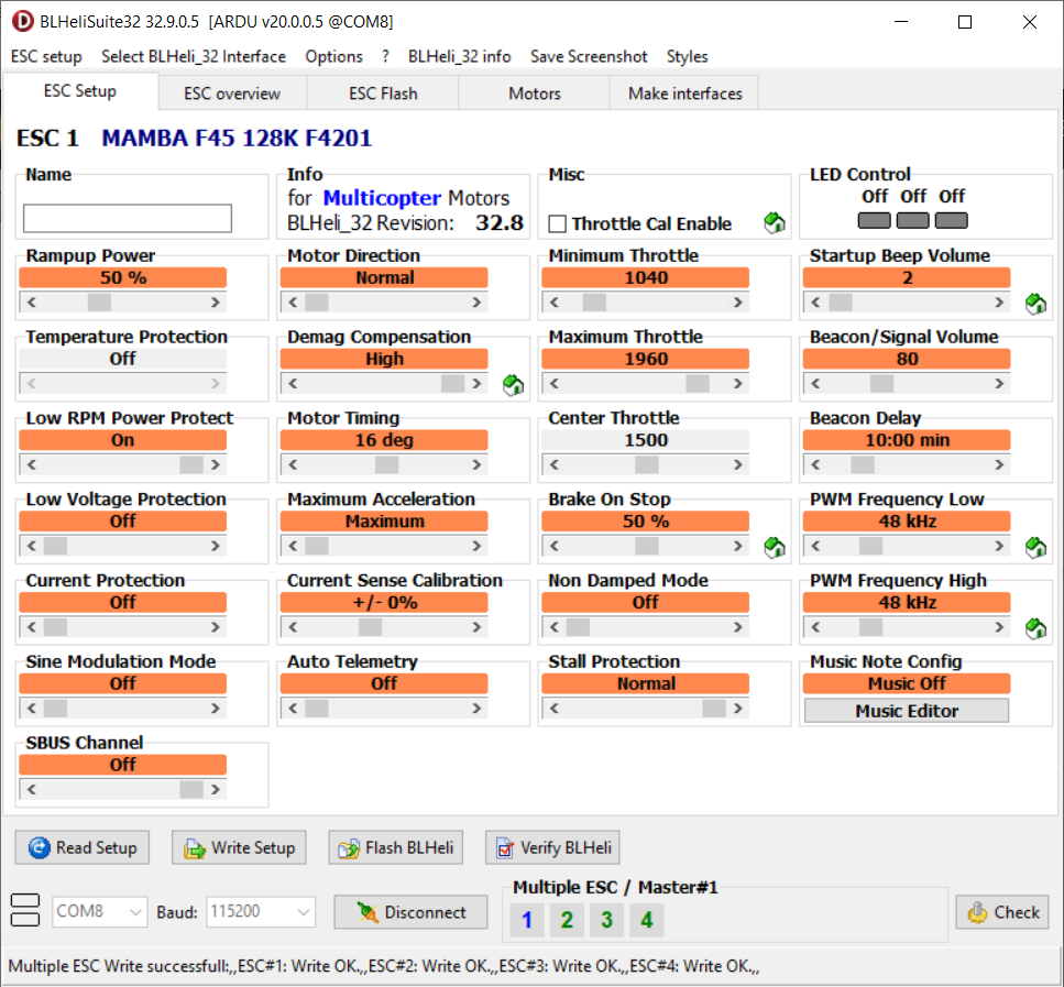
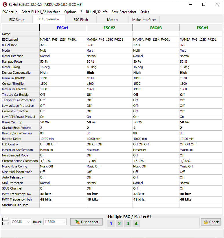
In our vehicle, we use BLHeli_32 ARM ESC firmware.
So we use BLHeliSuite32 Version 32.9.0.6 to configure the ESCs. Flash the Firmware version described in the table above. Configure the parameters to match the figures below.
 to stop desyncs and improve motor performance in your FPV quadcopter!")
2.9 Configure the primary battery monitor
In our setup, the battery voltage is measured directly at the flight controller Vbat pin and the current is measured at the 4-in1 ESC Curr pin.
Repeat the steps from section 2.5.1 to edit and upload the 08_batt1.param file
2.10 Configure the redundant (secondary) battery monitor
To be on the safe side we used a Holybro PM02 as a redundant secondary voltage and current monitor.
One other option would be the CBU 2-8s DroneCAN Battery Monitor and Current Sensor.
Repeat the steps from section 2.5.1 to edit and upload the 09_batt2.param file
2.11 Configure the GNSS receiver(s)
GNSS receivers very often contain a magnetometer (compass) sensor. So they need to be configured before proceeding to the next step.
Repeat the steps from section 2.5.1 to edit and upload the 10_gnss.param file
When asked Should the FC values now be copied to the 11_mp_setup_mandatory_hardware.param file? select No and close the ArduPilot Methodic Configurator software.
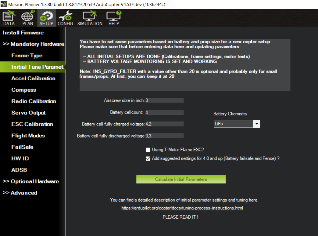
2.12 Configure “Mandatory Hardware” Parameters
Open Mission Planner, connect to the flight controller and select SETUP >> Mandatory Hardware and work yourself through all the submenus as described below. DO NOT SKIP ANY STEP.
Frame Type
This relates to the FRAME_CLASS and FRAME_TYPE parameters.
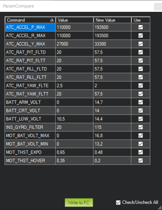
Initial Tune Parameters
Answer the questions that Mission Planner asks, select Add suggested settings for 4.0 and up (Battery failsafe and Fence) and upload the calculated parameters to the flight controller by pressing Upload to FC.
Accel Calibration
Follow the ArduPilot wiki instructions and calibrate the accelerometers.
For small vehicles use:
- Calibrate Accel
- Calibrate level
For very large vehicles:
- Simple Accel Cal
Compass
Follow the ArduPilot wiki instructions and calibrate the compass(es).
Disable internal compasses if the battery or power wires are close to the flight controller.
Do not select Automatically learn offsets it makes little sense on a multicopter.
And we will do in-flight MagFit later
If you have a large vehicle you might want to use large vehicle MagCal instead.
Radio Calibration
Follow the ArduPilot wiki instructions and calibrate the Remote Control.
Turn on your RC Transmitter and move the sticks around.
Make sure all transmitter channels move across their entire range.
Servo Output
Change the parameters according to your requirements.
ESC Calibration
Do not make changes here, these parameters will be set later on the Motor/Propeller order and direction test section
Flight Modes
Define the flight modes you plan to use.
Do not use POSHOLD, use LOITER instead.
Both only work outdoors because they require a good GNSS signal quality with low variance.
If that is not possible, GPS glitches will occur and ALTHOLD flight mode is recommended instead.
Failsafe
These are very important and can save your vehicle in case of failure.
Configure at least Radio Failsafe, Battery Failsafe and Geofence
HW ID
This is just informational. No need to change anything.
ADSB
Change the parameters according to your requirements.
Last step
The changes you did in the steps above have been stored in your vehicle.
Most of the changed parameters are vehicle-instance specific and can not be reused between two vehicles, no matter how similar they are.
Close Mission Planner.
2.13 General configuration
Now do some general configuration
- Connect the flight controller to the PC
- Start ArduPilot Methodic Configurator and select the vehicle directory where you previously stored your intermediate parameter files.
- When ArduPilot Methodic Configurator asks you Should the FC values now be copied to the 11_mp_setup_mandatory_hardware.param file? select
Yes - Select
12_general_configuration.paramon the Current intermediate parameter file: Combobox. - Read the documentation links inside the
12_general_configuration.param documentation - Edit the parameters’
New ValueandChange Reasonto suit your requirements - Press
Upload selected params to FC, and advance to next filebutton.
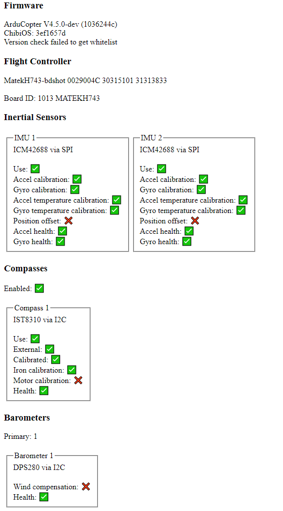
2.14 ArduPilot Hardware Report
For this test, you need to:
- Visit the ArduPilot Hardware report on your PC and upload the
.binfile you got in the previous section. - Take a look at the results
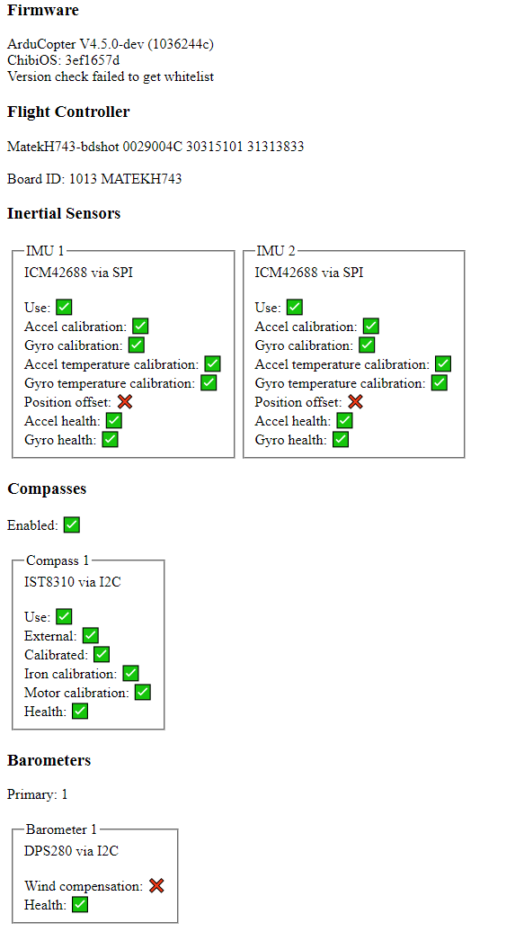
It should look like the following picture.
If it doesn’t, go back and perform the missing calibration(s).
2.15 Configure Logging
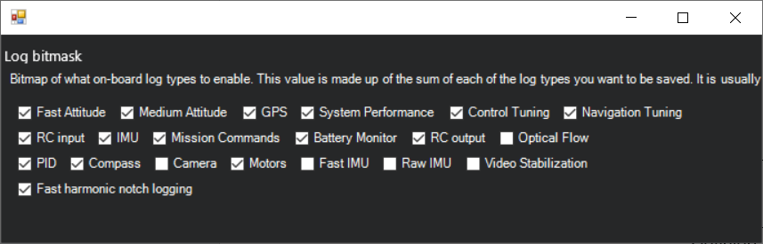
Repeat the steps from section 2.5.1 to edit and upload the 13_Logging.param file
The .bin message table explains which bit is responsible for which .bin dataflash log messages:
2.16 Motor/Propeller order and direction test
Start by checking the motor numbering with the Mission Planner Motor test without propellers. Remember the correct order is A, B, C, D and not 1, 2, 3, 4.
Make sure the MOT_SPIN_ARM is high enough so that all motors spin reliably.
Make sure the MOT_SPIN_MIN is at least 0.03 higher than MOT_SPIN_ARM.
!!! If you get this test wrong or skip it, you might destroy your vehicle and endanger yourself !!!
Do not try to test the attitude controller without propellers, it will not work, such tests are inconclusive and meaningless.
Do not try to test the attitude controller with the vehicle tied down on the ground, it will not work, such tests are inconclusive and meaningless.
At this point, the vehicle does not react to roll, pitch, yaw or thrust inputs.
Now mount the propellers on the vehicle.
After that, follow the setting Motor Range to adjust the motor demand by the flight controller to the limitations of the ESC.
Motor Thrust scaling (MOT_THST_EXPO, MOT_SPIN_MIN and MOT_SPIN_MAX)
These three parameters linearize (correct) the non-linear thrust vs. PWM response of the propulsion system (battery, ESC, motors, propellers).
They are crucial for the stability of the vehicle.
If this is set too high we see an increase in gain at the lower end of the thrust range and a decrease in gain at the upper end.
Therefore when set too high you can see instability at low throttle and if set too low you can see instability at high throttle.
The automation on SETUP >> Mandatory Hardware >> Initial Tune Parameters gave you a good starting point on their values.
But we recommend using a Trust Stand or Olliw method or ArduPilot DIY Thrust Stand to determine their value.
At the time of writing Automatic MOT_THST_EXPO estimation lua script is not yet ready for production use.
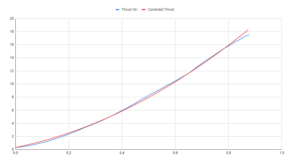
We used an oversized test stand to test the motors. Since the test stand was too big for a single motor we tested all four motors at once. This was our setup:
- Series 1780 test stand from Tyto Robotics
- Delta Elektronika SM66-AR-110 power supply
- T-Motor F1507 3800kv motors
- Mamba Systems F45_128k BLHeli32 4in1 ESC
- HQProp “DUCT-76MMX8” propellers
We fixed and updated Cell G8 as well as the plot’s Data range of the original ArduPilot Wiki Spreadsheet creating this corrected version
We imported the data into the spreadsheet and created this graph:
Repeat the steps from section 2.5.1 to edit and upload the 14_motor.param file
2.17 Optional PID adjustment
If you have a very small, or a very large vehicle that requires non-default PID values for a safe flight.
Usually, smaller vehicles require lower than default PID rate values. Larger vehicles usually require higher than default PID rate values.
Repeat the steps from section 2.5.1 to edit and upload the 15_pid_adjustment.param file
2.18 Remote ID (aka Drone ID)
Read and follow ArduPilot’s Remote ID setup instructions. You might have to build OpenDroneID firmware for production.
Repeat the steps from section 2.5.1 to edit and upload the 16_remote_id.param file
2.19 Notch filters setup
Configure the gyro noise reduction notch filters with an estimation of the operation parameters.
The estimation will be improved after the first flight.
Repeat the steps from section 2.5.1 to edit and upload the 17_notch_filter_setup.param file
When asked Should the FC values now be copied to the 18_notch_filter_results.param file? select No and close the ArduPilot Methodic Configurator software.
3. First flight: Motor Thrust Hover and Harmonic Notch data collection
For more detailed information visit the First flight
Test the initial setup on the ground in stabilize flight mode by using as little RC transmitter throttle as possible without taking off.
At this sweet spot, inspect all axes (roll, pitch and yaw) by providing small RC transmitter stick inputs.
If the multicopter behaves correspondingly, the setup is good to go.
After some careful test maneuvers switch to ALTHOLD and hover for 30 to 40 seconds one to two meters above the ground. Land and disarm.
Immediately check for hot motors.
If the motors are too hot, check the .bin dataflash log, high or oscillating RATE.*out values indicate which PID gain you should reduce to remove the output oscillations causing the motors to heat up.
3.1 Notch filter calibration
Load the .bin log from the first flight onto the online Ardupilot Filter Review tool
Follow the instructions from Peter Hall on his Blog Post to configure the Harmonic Notch filter(s).
The graph below is a bode diagram of the gyro signals before and after the low-pass and Harmonic Notch filters.
As you can see, the filters remove most of the vibration noise from the gyro sensors.
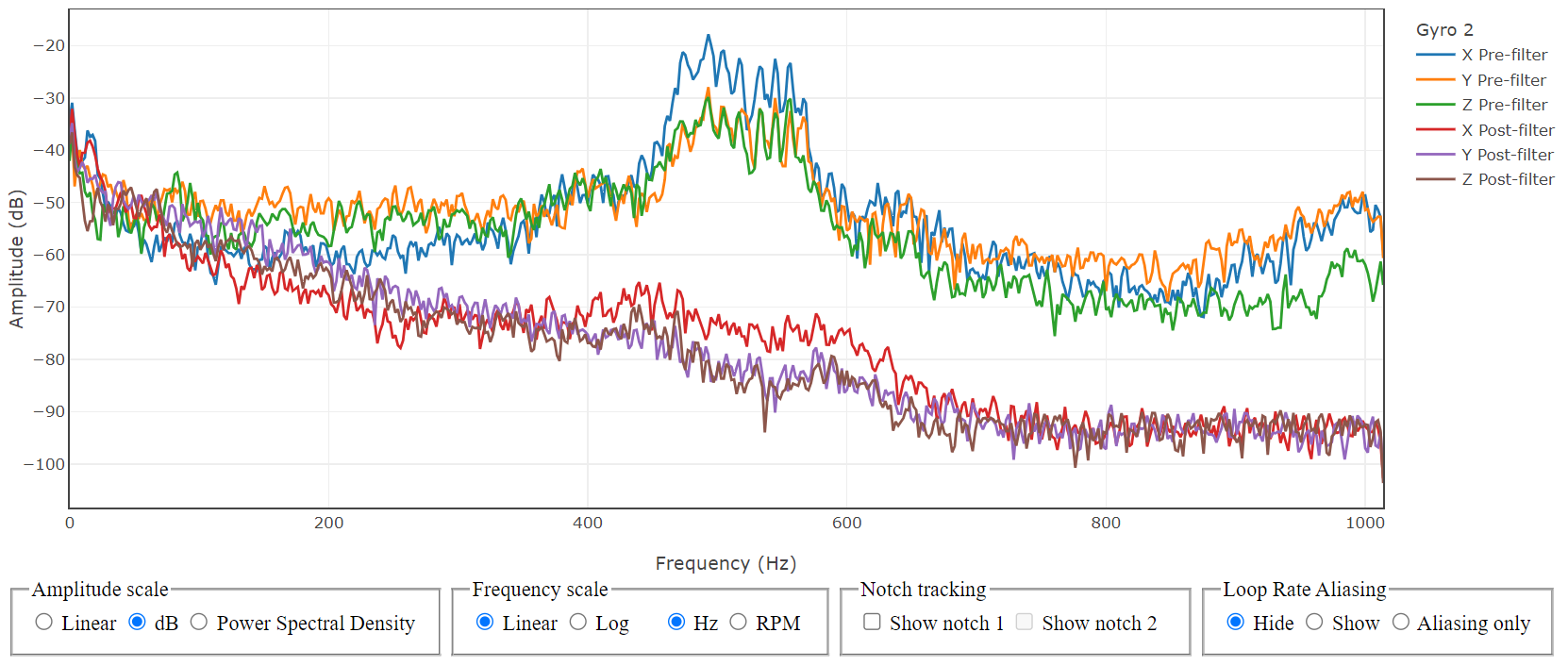
Below is the configuration we used.
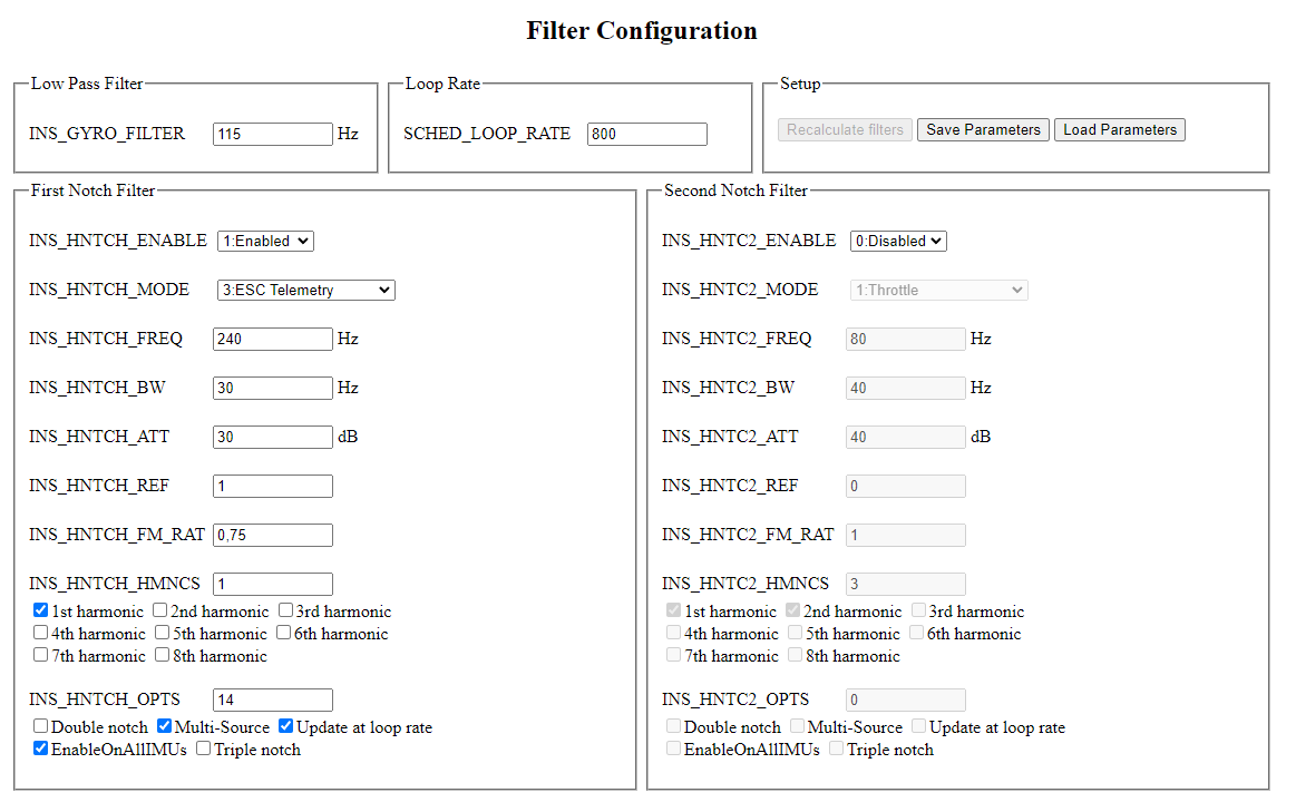
- On ArduPilot Methodic Configurator select
18_notch_filter_results.paramon the Current intermediate parameter file: Combobox. - When asked Should the FC values now be copied to the 18_notch_filter_results.param file? select
No. - Read the documentation links inside the
18_notch_filter_results.param documentation - Edit the parameters’
New ValueandChange Reasonto suit your requirements - Press
Upload selected params to FC, and advance to next filebutton.
Load the .bin log from the first flight onto the online Ardupilot Log Viewer or into Mission Planner.
Take a look at the VIBE.VibeX, VIBE.VibeY, VIBE.VibeZ graphs they all should be below 15
According to common ArduPilot forum knowledge, and quoting @xfacta:
- Vibrations over 30 are very bad
- Vibrations over 20 are causing issues even if you don’t know it yet
- Vibrations over 15 are in a grey area - it could go either way - check clipping, it must be zero
- Vibrations below 10 are good
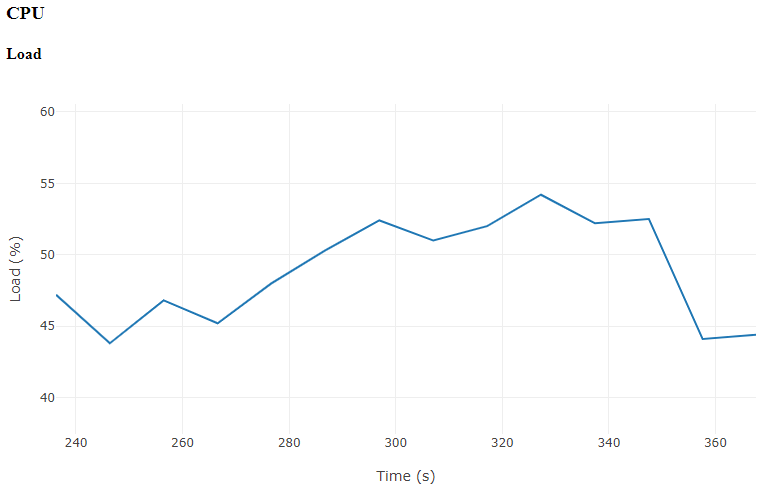
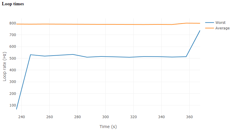
Now upload the .bin log to the Hardware-Report Tool once again to check CPU load and loop times, which in our case look like this:
3.2 Configure the throttle controller
Use the .bin log from the first flight to set the parameters described on the 19_throttle_controller.param file.
4. Second Flight: PID VTOL-Quiktune lua script or manual PID tune
If your flight controller can run lua scripts perform a PID lua VTOL-Quicktune.
If you have an STM32 F4 or F7 processor that can not run lua scripts perform a manual PID tune instead.
Setup the lua script using:
- Download the VTOL-quicktune.lua to your PC
- connect your flight controller to the PC
- Copy the script to your autopilot’s SD card’s APM/scripts directory. If using MP it may be easiest to use the Config, MAVFtp screen.
- Close mission planner, open ArduPilot Methodic Configurator and select your vehicle’s directory
- On ArduPilot Methodic Configurator select
20_quicktune_setup.paramon the Current intermediate parameter file: Combobox. - Read the documentation links inside the
20_quicktune_setup.param documentation - Edit the parameters’
New ValueandChange Reasonto suit your requirements - Press
Upload selected params to FC, and advance to next filebutton. - Close ArduPilot Methodic Configurator
Perform the flight and afterward:
- Connect the flight controller to the PC
- On ArduPilot Methodic Configurator select
21_quicktune_results.paramon the Current intermediate parameter file: Combobox. - When asked Should the FC values now be copied to the 21_quicktune_results.param file? select
Yes. - Press
Upload selected params to FC, and advance to next filebutton. - Close ArduPilot Methodic Configurator
If you are impatient and do not want a fully optimized flight controller jump to section 14 Productive configuration
5. Third flight: MagFit
Now that the Harmonic Notch filter, the throttle controller and PIDs are configured, the third flight will be safer.
This flight will be used to calibrate the compass during a realistic operation scenario in the air.
Inflight MagFit calibration
Follow these steps before the flight:
- Download the
copter-magfit-helper.luaandadvance-wp.luascripts from Scripted MagFit flightpath generation and put them on the micro SDCard’sAPM/scriptsfolder - insert the SD-Card on the flight controller
- connect your flight controller to the PC
- On ArduPilot Methodic Configurator select
22_inflight_magnetometer_fit_setup.paramon the Current intermediate parameter file: Combobox. - Read the documentation links inside the
22_inflight_magnetometer_fit_setup.param documentation - Edit the parameters’
New ValueandChange Reasonto suit your requirements - Press
Upload selected params to FC, and advance to next filebutton. - When asked Should the FC values now be copied to the 23_inflight_magnetometer_fit_results.param file? select
No. - Close ArduPilot Methodic Configurator
Perform the MagFit figure-eight flight and land
- Download the latest
.bindataflash log file from the micro SDcard’s/APM/LOGSfolder - Load it into MAVExplorer using the command line:
MAVExplorer.py filename.binor into the ArduPilot MAGFit in flight compass calibration using an internet browser. - Select the area where the multicopter performed the Figure eight (exclude the takeoff and landing flight sections)
- Perform the MagFit calculations. Save the tool-generated file as
23_inflight_magnetometer_fit_results.paramin your vehicle’s intermediate parameter file directory. - connect your flight controller to the PC
- On ArduPilot Methodic Configurator select
23_inflight_magnetometer_fit_results.paramon the Current intermediate parameter file: Combobox. - When asked Should the FC values now be copied to the 23_inflight_magnetometer_fit_results.param file? select
Yes. - Press
Upload selected params to FC, and advance to next filebutton. - Close ArduPilot Methodic Configurator
After that repeat the steps described in 2.14 ArduPilot Hardware Report.
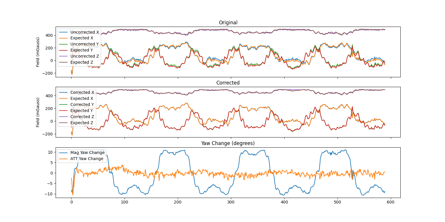
The report should now look like this:
6. Fourth Flight: PID VTOL-Quiktune lua script or manual PID tune (optional)
If your flight controller can run lua scripts perform a PID lua VTOL-Quicktune.
If you have an STM32 F4 or F7 processor that can not run lua scripts perform a manual PID tune instead.
Setup the lua script using:
- Download the VTOL-quicktune.lua to your PC
- connect your flight controller to the PC
- Copy the script to your autopilot’s SD card’s APM/scripts directory. If using MP it may be easiest to use the Config, MAVFtp screen.
- Close mission planner, open ArduPilot Methodic Configurator and select your vehicle’s directory
- On ArduPilot Methodic Configurator select
24_quicktune_setup.paramon the Current intermediate parameter file: Combobox. - Read the documentation links inside the
24_quicktune_setup.param documentation - Edit the parameters’
New ValueandChange Reasonto suit your requirements - Press
Upload selected params to FC, and advance to next filebutton. - When asked Should the FC values now be copied to the 25_quicktune_results.param file? select
No. - Close ArduPilot Methodic Configurator
Perform the flight and afterward:
- Connect the flight controller to the PC
- On ArduPilot Methodic Configurator select
25_quicktune_results.paramon the Current intermediate parameter file: Combobox. - When asked Should the FC values now be copied to the 25_quicktune_results.param file? select
Yes. - Press
Upload selected params to FC, and advance to next filebutton. - Close ArduPilot Methodic Configurator
If you are impatient and do not want a fully optimized flight controller jump to section 14 Productive configuration
7. Fifth flight: Evaluate the aircraft tune - part 1
Follow the first part of evaluating the aircraft tune.
- On ArduPilot Methodic Configurator select
26_evaluate_the_aircraft_tune_ff_disable.paramon the Current intermediate parameter file: Combobox. - Read the documentation links inside the
26_evaluate_the_aircraft_tune_ff_disable.param documentation - Press
Upload selected params to FC, and advance to next filebutton. - Close ArduPilot Methodic Configurator
After landing take a look at the RATE.*out values in the .bin log file, they all should be below 0.1.
If the vehicle is not behaving well, perform a manual PID tune or a lua Quicktune before proceeding.
8. Sixth flight: Evaluate the aircraft tune - part 2
Follow the second part of evaluating the aircraft tune.
- On ArduPilot Methodic Configurator select
27_evaluate_the_aircraft_tune_ff_enable.paramon the Current intermediate parameter file: Combobox. - Read the documentation links inside the
27_evaluate_the_aircraft_tune_ff_enable.param documentation - Press
Upload selected params to FC, and advance to next filebutton. - Close ArduPilot Methodic Configurator
After landing take a look at the RATE.*out values in the .bin log file, they all should be below 0.1.
9. Autotune flight(s)
The Autotune is an automated iterative process:
- It changes the parameter values of the attitude PID controllers
- Tests the overshoot and settling-time of the control loop using the new PID values
- If they are within the desired requirements, the process is over. If not, it gets repeated from the beginning
If the battery gets depleted before you can complete the Autotune flight(s), download the latest .bin log file from the micro SDCard directory /APM/LOGS.
Take a look at the ATUN messages.
They show how the PID values change over time.
You should use the latest PID values from the ATUN messages to set the starting point of your next PID Autotune with a fresh battery.
But be careful, these new PID values might be unstable and cause your vehicle to crash.
To be on the safe side perform the third and fourth flights again according to the instructions above.
This way, the Autotune will restart from the partially optimal values it found before the battery got depleted, instead of starting from scratch.
An example of the relevant ATUN message data of an interrupted yaw Autotune .bin dataflash log is depicted below:
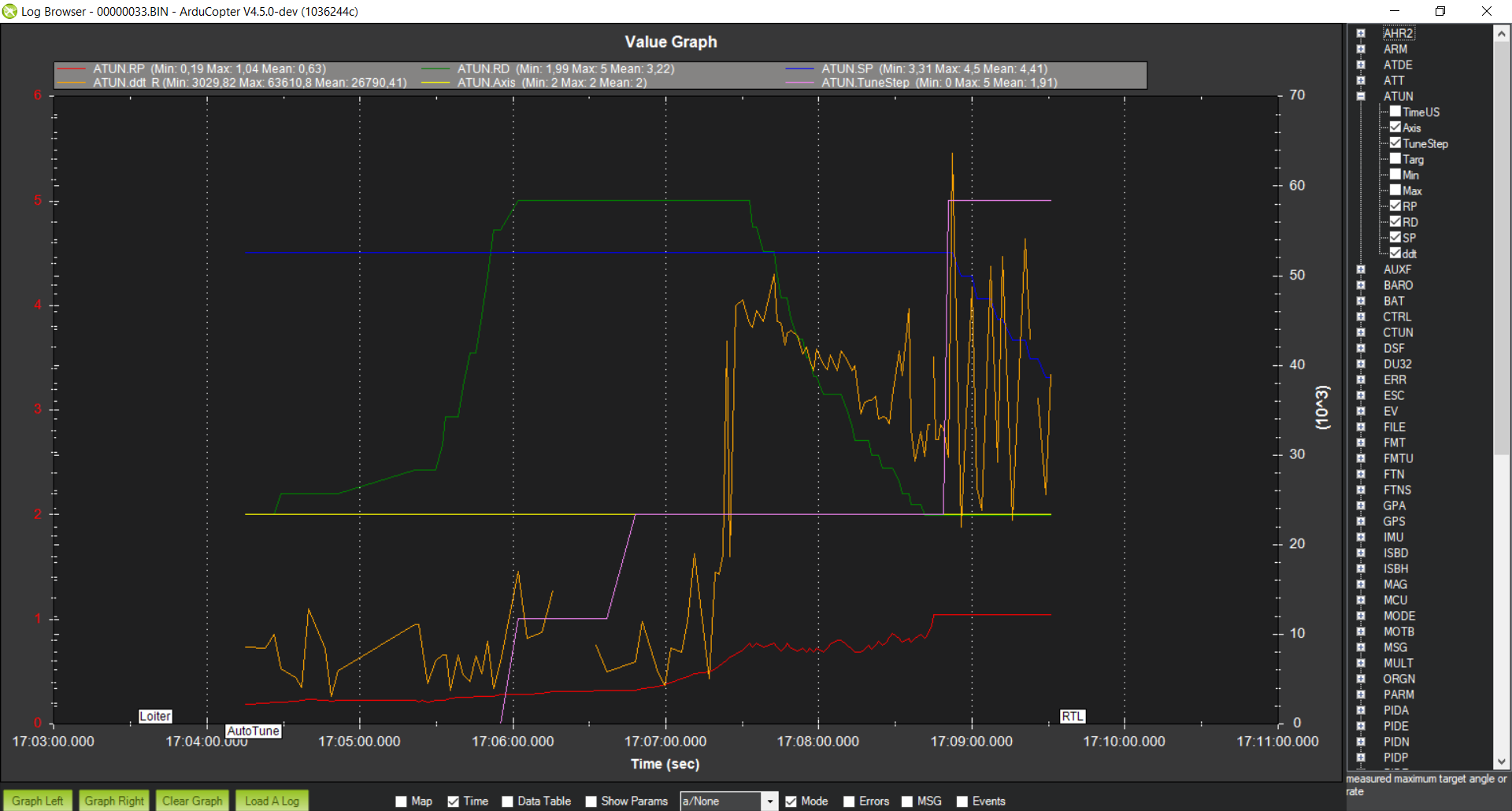
The correspondence between the PIDs’ initial values and the ATUN message fields is shown in the respective tables for each of the four Autotune axes in the sections below.
The tune of the vehicle must be done in the vehicle’s most agile configuration.
That is, the vehicle will be at its minimum take-off weight with fully charged batteries.
This is why we will do Autotune with multiple flights, one axis per flight.
Typically the quality of the Autotune results for each axis is proportional to the value of the ATC_ANG_RLL_P, ATC_ANG_PIT_P, and ATC_ANG_YAW_P parameters for their respective axis.
Also the higher the values, the tighter the tune.
If you get low values, improve the hardware and revisit the previous sections to further reduce the vibrations.
Autotuning in low-wind conditions is desirable, but if that is not possible you can increase the AUTOTUNE_AGGR parameter value to 0.110 or even 0.120.
That is a workaround and will not produce as good results as low-wind conditions autotune.
We set up the autotune as a flight mode, and as such it will use the underlying ALTHOLD flight mode.
If you want to use the LOITER flight mode as the underlying mode during autotune you need to set an RC channel function switch to autotune.
Follow the sequence below for tuning each axis as that particular order improves the results.
Roll axis
- On ArduPilot Methodic Configurator select
28_autotune_roll_setup.paramand upload it to the FC. It will activate the roll axis Autotune. - When asked Should the FC values now be copied to the 29_autotune_roll_results.param file? select
No. - Outdoors on a non-windy day (or indoors in a big warehouse like we at IAV do) take off and fly in either
AltHoldorLoiterflight mode. - At about 2 meters high, select
Autotuneflight mode in the RC transmitter to engage Autotune. - Use the RC transmitter sticks to correct the vehicle position if it gets too high, too low or too close to obstacles.
- Once the Autotune is completed, land and disarm the vehicle without changing the flight mode.
- connect the flight controller to the PC
- On ArduPilot Methodic Configurator select
29_autotune_roll_results.param. - When asked Should the FC values now be copied to the 29_autotune_roll_results.param file? select
Yes.
The autotune might have found a poor solution, here are some indicators of a poor tune:
- The resulting
ATC_ANG_RLL_Pparameter value is smaller than 4.5 - The resulting
ATC_RAT_RLL_Dparameter value is equal to theAUTOTUNE_MIN_Dparameter value
If the battery got depleted before Autotune completion, change the initial PID parameters as shown in the table below:
| PID parameter name | PID parameter value based on the ATUN field |
|---|---|
| - | ATUN.Axis=0 |
| ATC_RAT_RLL_P | ATUN.RP |
| ATC_RAT_RLL_I | ATUN.RP |
| ATC_RAT_RLL_D | ATUN.RD |
| ATC_ANG_RLL_P | ATUN.SP |
| ATC_ACCEL_R_MAX | ATUN.ddt |
Pitch axis
- On ArduPilot Methodic Configurator select
30_autotune_pitch_setup.paramand upload it to the FC. It will activate the pitch axis Autotune. - When asked Should the FC values now be copied to the 31_autotune_pitch_results.param file? select
No. - Outdoors on a non-windy day (or indoors in a big warehouse like we at IAV do) take off and fly in either
AltHoldorLoiterflight mode. - At about 2 meters high, select
Autotuneflight mode in the RC Transmitter to engage Autotune. - Use the RC transmitter sticks to correct the vehicle position if it gets too high, too low or too close to obstacles.
- Once the autotune is completed, land and disarm the vehicle without changing the flight mode.
- connect the flight controller to the PC
- On ArduPilot Methodic Configurator select
31_autotune_pitch_results.param. - When asked Should the FC values now be copied to the 31_autotune_pitch_results.param file? select
Yes.
The autotune might have found a poor solution, here are some indicators of a poor tune:
- The resulting
ATC_ANG_PIT_Pparameter value is smaller than 4.5 - The resulting
ATC_RAT_PIT_Dparameter value is equal to theAUTOTUNE_MIN_Dparameter value
If the battery got depleted before Autotune completion, change the initial PID parameters as shown in the table below:
| PID parameter name | PID parameter value based on the ATUN field |
|---|---|
| - | ATUN.Axis=1 |
| ATC_RAT_PIT_P | ATUN.RP |
| ATC_RAT_PIT_I | ATUN.RP |
| ATC_RAT_PIT_D | ATUN.RD |
| ATC_ANG_PIT_P | ATUN.SP |
| ATC_ACCEL_P_MAX | ATUN.ddt |
Yaw axis
- Use ArduPilot Methodic Configurator to edit and upload the
32_autotune_yaw_setup.paramfile to the FC. It will activate the yaw axis Autotune. - Outdoors on a non-windy day (or indoors in a big warehouse like we at IAV do) take off and fly in either
AltHoldorLoiterflight mode. - At about 2 meters high, select
Autotuneflight mode in the RC transmitter to engage Autotune. - Use the RC transmitter sticks to correct the vehicle position if it gets too high, too low, or too close to obstacles.
- Once the Autotune is completed, land and disarm the vehicle without changing the flight mode.
You should get something like the 33_autotune_yaw_results.param file.
The autotune might have found a poor solution, here are some indicators of a poor tune:
- The resulting
ATC_ANG_YAW_Pparameter value is smaller than 4.5
If the battery got depleted before Autotune completion, change the initial PID parameters as shown in the table below:
| PID parameter name | PID parameter value based on the ATUN field |
|---|---|
| - | ATUN.Axis=2 |
| ATC_RAT_YAW_P | ATUN.RP |
| ATC_RAT_YAW_I | ATUN.RP * 0.1 |
| ATC_RAT_YAW_FLTE | ATUN.RD |
| ATC_ANG_YAW_P | ATUN.SP |
| ATC_ACCEL_Y_MAX | ATUN.ddt |
Yaw D axis
This particular YawD Autotune axis is only relevant for small, agile vehicles.
- Use ArduPilot Methodic Configurator to edit and upload the
34_autotune_yawd_setup.paramfile to the FC. - Outdoors on a non-windy day (or indoors in a big warehouse like we at IAV do) take-off and fly in either
AltHoldorLoiterflight mode. - At about 2 meters high, select
Autotuneflight mode in the RC transmitter to engage Autotune. - Use the RC transmitter sticks to correct the vehicle position if it gets too high, too low or too close to obstacles.
- Once the Autotune is completed, land and disarm the vehicle without changing the flight mode.
You should get something like the 35_autotune_yawd_results.param file.
Make sure that your resulting ATC_RAT_YAW_D parameter value is different from AUTOTUNE_MIN_D value.
If that is not the case then the autotune failed to find a proper ATC_RAT_YAW_D.
The cause is probably too high noise values at the input of the Yaw D controller.
If the battery got depleted before Autotune completion, change the initial PID parameters as shown in the table below:
| PID parameter name | PID parameter value based on the ATUN field |
|---|---|
| - | ATUN.Axis=3 |
| ATC_RAT_YAW_P | ATUN.RP |
| ATC_RAT_YAW_I | ATUN.RP * 0.1 |
| ATC_RAT_YAW_D | ATUN.RD |
| ATC_ANG_YAW_P | ATUN.SP |
| ATC_ACCEL_Y_MAX | ATUN.ddt |
re-tune the roll and pitch axis
Now that the yaw axis is tuned, the autotune should be able to improve the roll and pitch axis tune.
- Use ArduPilot Methodic Configurator to edit and upload the
36_autotune_roll_pitch_retune_setup.paramfile to the FC. - Outdoors on a non-windy day (or indoors in a big warehouse like we at IAV do) take off and fly in either
AltHoldorLoiterflight mode. - At about 2 meters high, select
Autotuneflight mode in the RC transmitter to engage Autotune. - Use the RC transmitter sticks to correct the vehicle position if it gets too high, too low or too close to obstacles.
- Once the Autotune is completed, land and disarm the vehicle without changing the flight mode.
You should get something like the 37_autotune_roll_pitch_retune_results.param file.
10. Performance evaluation flight
As you can see in the picture below, the Stabilize Roll, Pitch and Yaw P gains achieved with this method are high. The maximum stabilize P gain that autotune strives for is 36, and that was achieved in the roll axis! This is a clear indication that the vibration noise filters and the PID control loops are working well together.
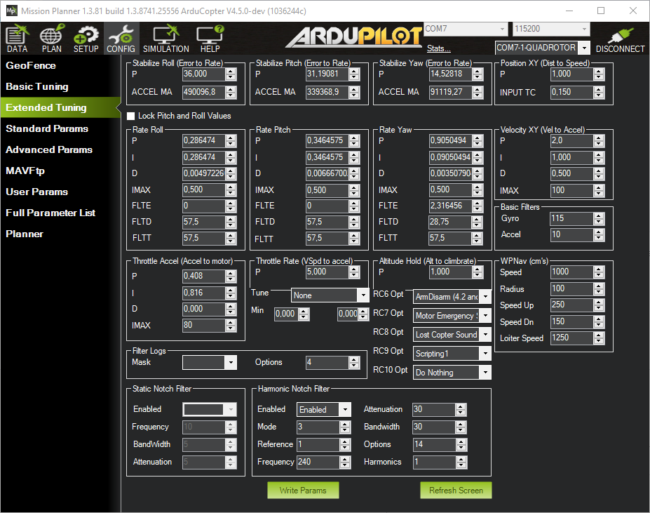
After using Autotune to find proper PID parameters, it is time to evaluate the performance of the vehicle’s control loops in real flight.
Follow these steps:
- Power on the vehicle and connect it to the PC
- Use ArduPilot Methodic Configurator to upload the
26_evaluate_the_aircraft_tune_ff_disable.paramfile to the FC. - Switch to
ALTHOLDflight mode and wait for home location acquisition. - Take-off at around 10m above the ground.
- Perform smooth maneuvers using the RC transmitter roll stick.
- Perform smooth maneuvers using the RC transmitter pitch stick.
- Perform smooth maneuvers using the RC transmitter yaw stick.
- Repeat the maneuvers with increasing aggressivity making sure you stay inside the stable envelope of the vehicle.
- Land and download the latest
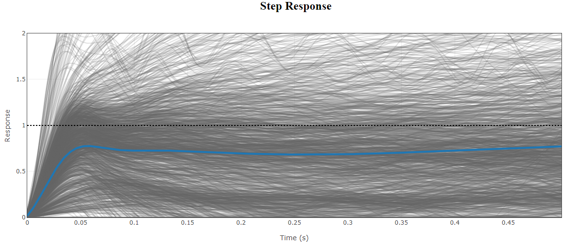
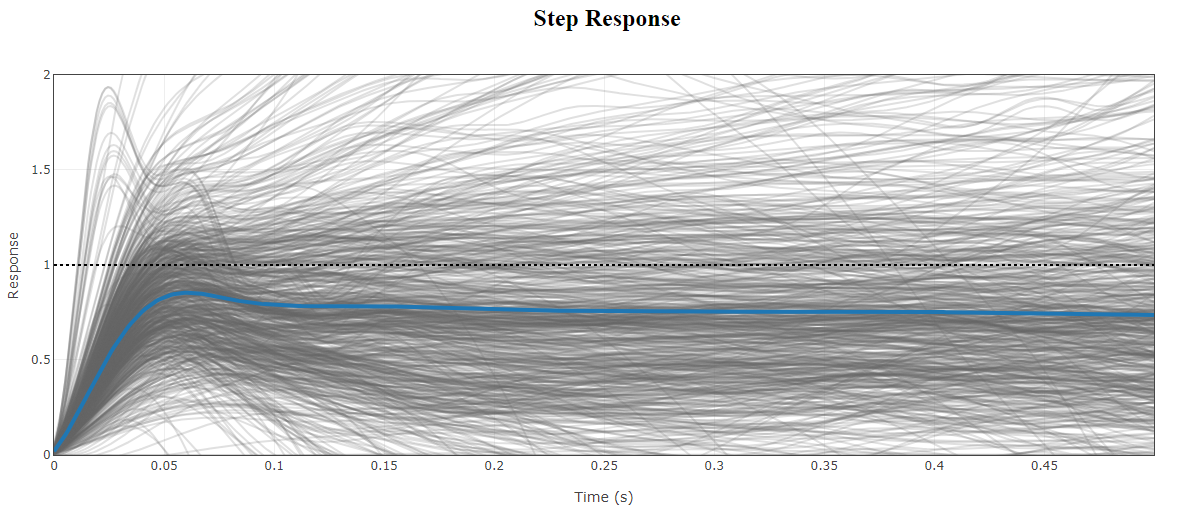
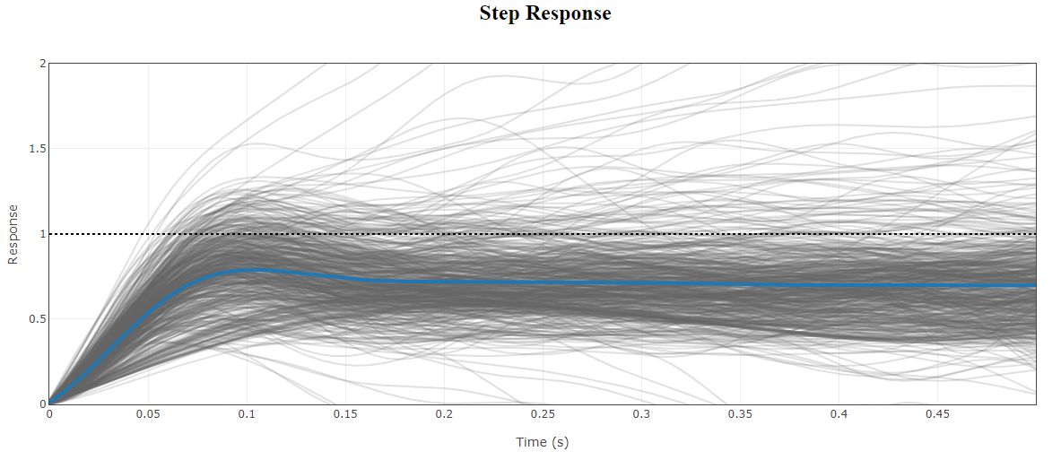
.binlog file from/APM/LOGSto your PC - Use ArduPilot’s PID Review Tool to review the PID step response of each PID.
- Use ArduPilot Methodic Configurator to upload the
27_evaluate_the_aircraft_tune_ff_enable.paramfile to the FC.
In our vehicle, we got a transient response of around 60ms in roll and pitch and around 110ms in yaw.
Step response Roll:
Step response Pitch:
Step response Yaw:
If you are satisfied with the performance, increase ATC_THR_MIX_MAX to 0.9 (default is 0.5) to increase prioritization of attitude control over throttle.
This can reduce the pitch overshoot sometimes seen (especially on copters with large propellers) in AltHold if the vehicle suddenly slows after performing a fast-forward flight.
Take a look at the RATE.*out values in the .bin log file, they all should be below 0.1.
11. Windspeed Estimation flight(s)
Follow ArduCopter’s airspeed estimation Wiki and/or use the Lua script provided by Yuri in the forum.
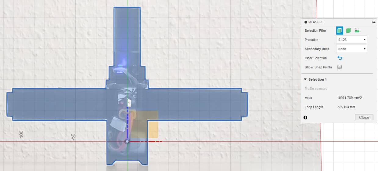
In our case, the frontal area looks like this:
and the side area looks like this:
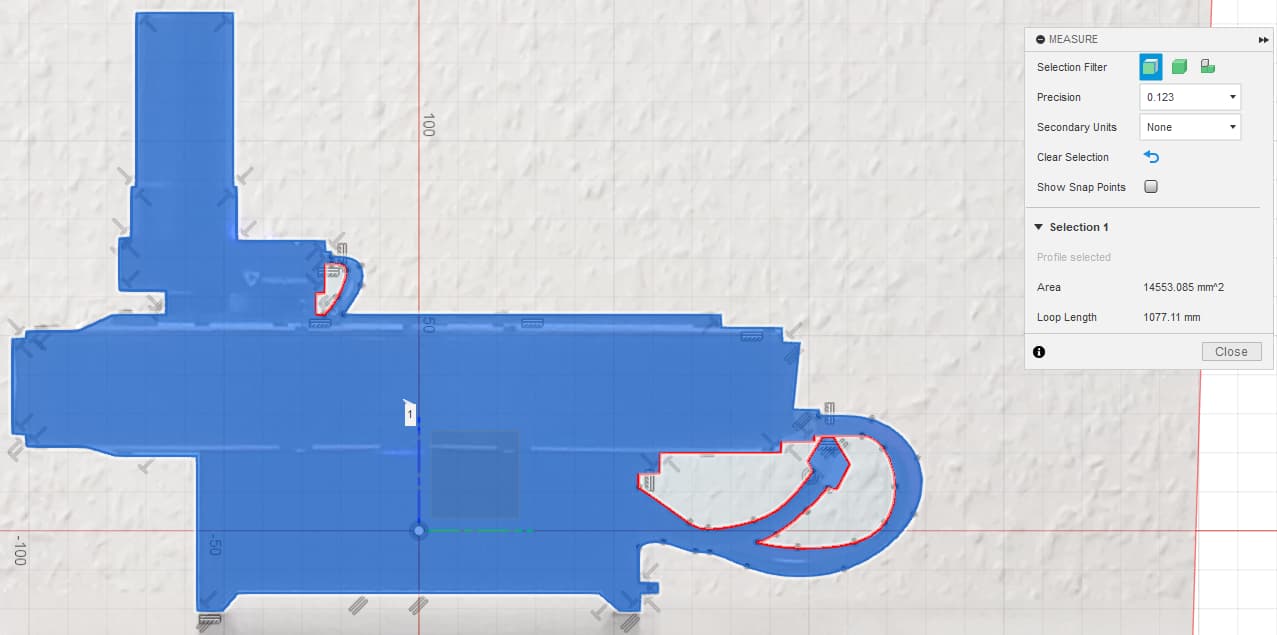
Divided by 1,000,000 to convert from mm² to m², the frontal area is 0.01097 m² and the side area is 0.01455 m².
The weight of our drone is 560g, therefore the ballistic coefficients are
- EK3_DRAG_BCOEF_X = 0.56 kg / 0.01097 m² = 51.0399
- EK3_DRAG_BCOEF_Y = 0.56 kg / 0.01455 m² = 38.4798
Use ArduPilot Methodic Configurator to edit and upload the 38_windspeed_estimation.param file to the FC.
Now do the flight to collect the data to Calculate the Propeller Drag Coefficient.
After that, open the logs with MAVExplorer to get the needed values.
Display the absolute values for acceleration in X and Y, as well as GPS speed by inputting graph abs(IMU.AccX) abs(IMU.AccY) GPS.Spd.
Then crop it so you only see the tests in AltHold flight mode.
It should look like this:
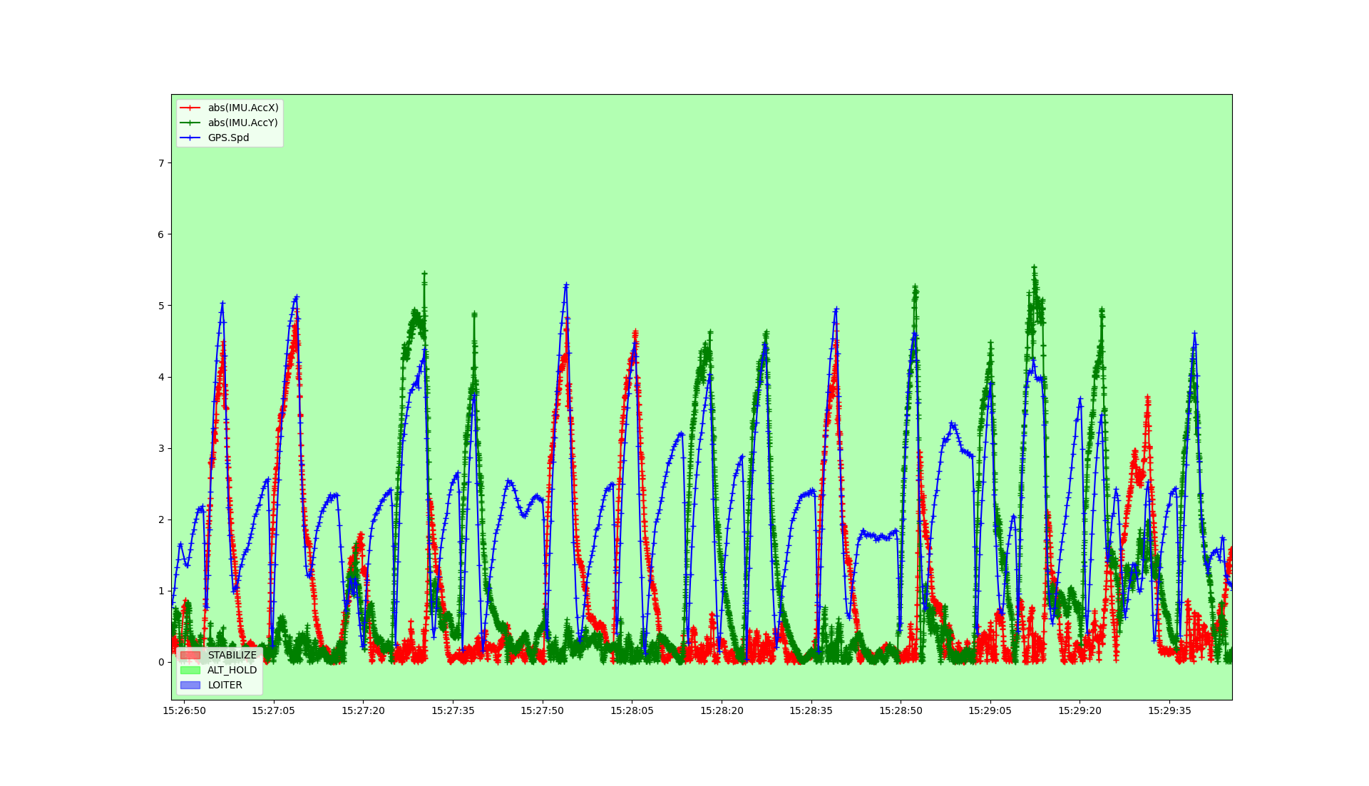
Note that our test flight was quite noisy but there is enough data to extract.
Next crop it so you see one acceleration into the wind and the consecutive deceleration.
It should look like this:
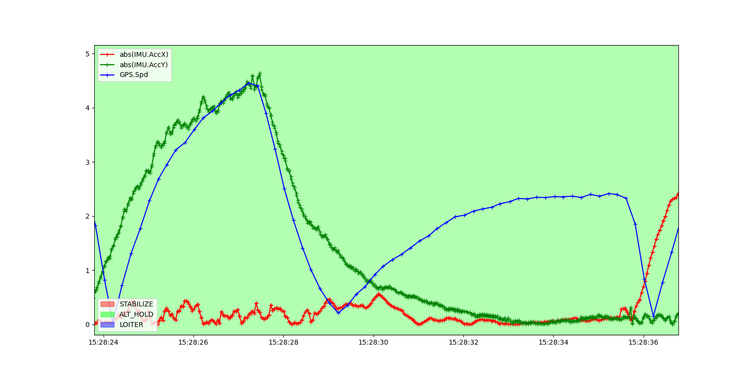
Get the current wind speed, that is the GPS speed when AccY reaches zero and the GPS speed has stabilized. In this case, it is:
- windspeed = 2.35 [m/s]
Next, get the groundspeed at the start of the test.
That is the GPS speed when the vehicle starts to decelerate after the little bit of jitter is over.
In this case, it is:
- groundspeed = 3.9 [m/s]
With this information, you can calculate the vehicle’s airspeed, which is:
- airspeed = windspeed + groundspeed = 6.25 [m/s]
Next get the maximum acceleration during the test, which is the acceleration at the time of the groundspeed measurement.
In this case, it is:
- max_accel = 4.2 [m/s²]
With the air density at the time of testing and the previously calculated ballistic drag coefficient (EK3_DRAG_BCOEF_X for front and back, EK3_DRAG_BCOEF_Y for left and right side) you can now calculate the bluff body drag, which is 1/2 * air density * airspeed^2 / BCOEF.
In this case, it is:
- Bluff body drag = 0.5 * 1.260 [kg/m³] * (6.25 [m/s])² / 38.4798 [kg/m²] = 0.6395 [m/s²]
With that, you can now calculate the momentum drag, which is max_accel - bluff body drag.
In this case, it is:
- Momentum drag = 4.2 [m/s²] - 0.6395 [m/s²] = 3.5605 [m/s²]
Now you can calculate the momentum drag coefficient EK3_DRAG_MCOEF, which is momentum drag / airspeed.
In this case, it is:
- EK3_DRAG_MCOEF = 3.5605 [m/s²] / 6.25 [m/s] = 0.5697 [1/s]
This Blog post continues below in the second post.