About the Project
This is a fun project that I have been working on, for the past few months, that I would like to share with everyone. I have been designing a suite of tools to help members of the community make a more informed decision around powertrain selection and to assist in capturing thrust expo data for tuning copters and such.
Central to these tools is an ArduPilot based thrust stand. This thrust stand has the following features:
- Logging: Throttle, thrust, torque, voltage, current, motor commutations (RPM), time stamp.
- ESC Logging: If using a BL Heli ESC then it also logs ESC current, ESC RPM, ESC temp, ESC Voltage.
- Throttle ramp mode: Gradually raises throttle to maximum (set as a param), pausing at 10 increments to capture steady-state response.
- Throttle transient mode: Ramps throttle to ‘hover throttle’ and then proceeds to run through a table of step inputs about the hover throttle to capture transient behaviour. (The implementation of this still needs refining).
- Over-current protection: Set a parameter value for max current. When exceeded the throttle is zeroed and the system stops to prevent damaging ESCs and motors on test, with the screen and lights informing the user.
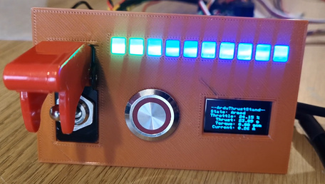
- Display: Addressable LEDs used for throttle bar. OLED display used for on-screen feedback of throttle, thrust, torque, current, and voltage.
- Safety: Building on ArduPilots already proven motor safety, ‘vehicle’ arming and disarming, is used just in-case the script dies, cutting the motor. Pendant ‘dead-mans’ button for operating the motor.
- Telemetry: A WiFi hotspot makes it easy to use a GCS for live remote telemetry and control. Plus using MAVFTP makes data retrieval very easy.
This project is totally open source. All of the code, CAD, and details of the components used are going to be shared. Just bear with me whilst I collate all of this information and make it available. All will be done through this thread.
Project Objectives
Perhaps the best way to help others understand some of the decisions I have made along the way is to explain what I wanted to achieve:
- Develop a set of tools that will be useful for the AP community (and perhaps wider).
- Make the project accessible. More specifically, accessible to build the hardware at a reasonable price. There are a lot of 3D printers in the community, hence a heavy reliance on this method of manufacturing.
- To use AP’s scripting to offer an example of a larger scripting project that is a bit outside of the examples provided thus far to hopefully encourage more people to have a go with the friendly development environment that scripting offers.
This Blog
As and when I have chance, I am going to keep adding to the information here through a number of posts. Broadly I plan to follow this order:
- Intro of the project: This post
- Hardware: An overview of all the parts I used and why.
- Manufacture: How the bits I designed are made.
- Data Processor: An introduction of how to access, use, and contribute to the post-processing tool I have been making.
Adaptability
Something I am quite pleased about with the way this project turned out is that there is a lot of flexibility. Not everyone will necessarily need/want torque data for example, so they can easily get one of the low-cost thrust stands off of bang good and plumb the load cell from that into this system to get more data and better automation. That makes the project way more accessible with just some 3D printing and soldering and your away.
The Back Story
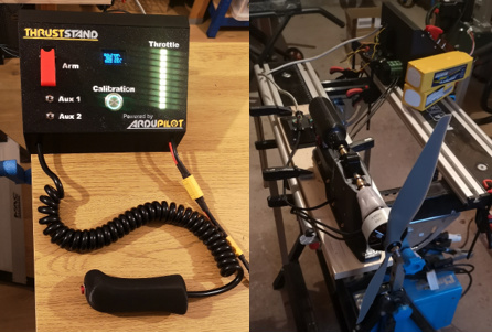
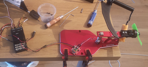
Talking of the Mayatech thrust stand, that is in fact how this project began. I got one of these stands and stripped off the LCD screen and buttons and started building up from there:
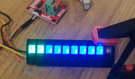
Gradually I added more functionality, adding in the LED bar, voltage and current monitoring, OLED display, and RPM from electrical commutations:
It was after this that I started working on capturing torque. This necessitated designing a new stand. I did try a couple of different layouts of using load cells to get both thrust and torque. The issue I regularly run into was that the data wasn’t coming out very clean. It would either get some noise from vibrations due to mass imbalance on the motor/prop or there would be cross-coupling between the two load cells. Now, I could have spent more time in decoupling the load cells in the script or in the postprocessor, as that is how many thrust stands work. However, I decided to go down the route of mechanically decoupling the thrust and torque sensors through the use of bearings and bushings. I was quite pleased with the result I was getting. This is the design of the thrust stand that I ended up with:

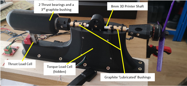
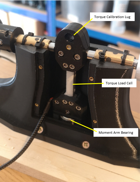
With this design the motor is attached to the shaft. The shaft is free to translate along and rotate about its axis. The torque load cell is clamped and bolted through the shaft. The lower bearing provides a single point of contact so that a pure bending moment is applied to the sensor. Inside the long black section at the back, two thrust bearings and a bushing are used to allow rotation but transfer the thrust load to the load cell at the back.
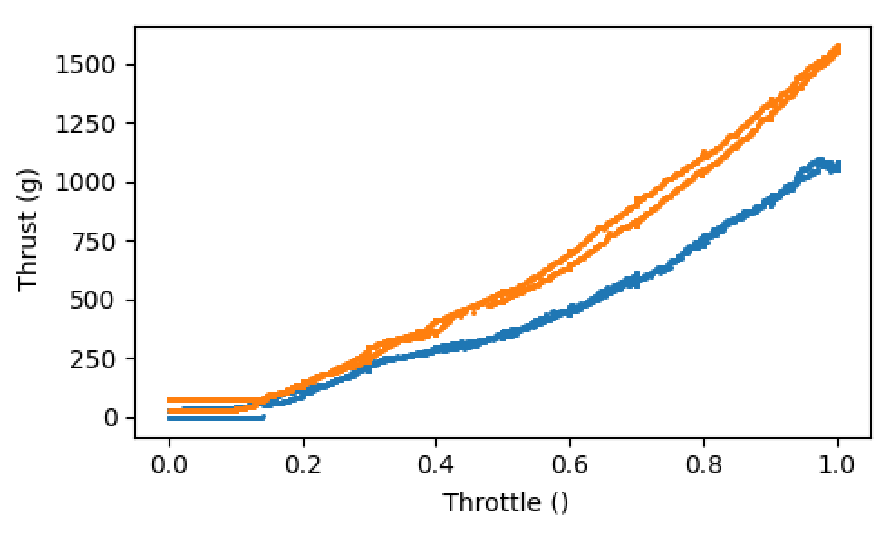
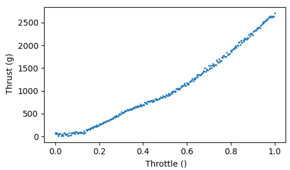
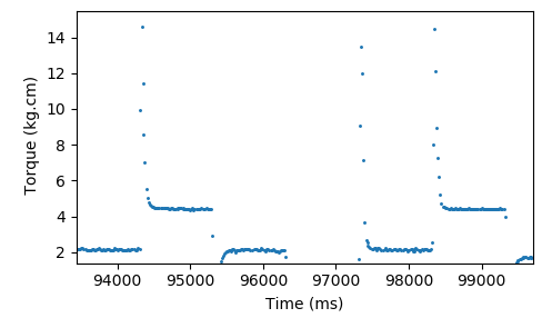
Despite all that I have done to reduce friction, there will no doubt be some hysteresis in the system. I counter that by always running a ramp up and a ramp down to a) understand how bad the hysteresis is and b) be able to remove the effects of it in post-processing. The two graphs below show an example of the outputs I get for thrust and torque in a throttle ramp test:
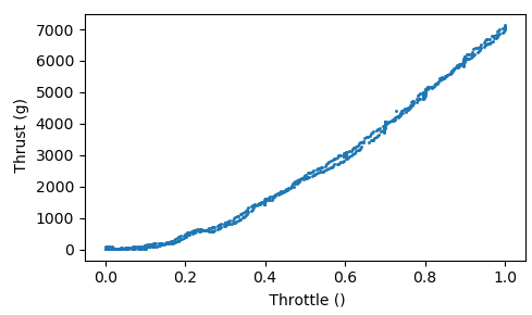
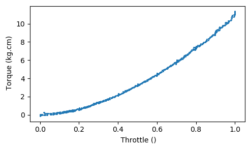
There is a ramp up and down in that data set, so I think you will agree that the hysteresis is minimal. As for repeatability, I have run countless tests on this rig now and always found very good agreement between repeat runs, the only difference being the effects of slightly lower voltage in subsequent runs.
Finally, this led me onto adding a new throttle mode to capture transient behaviour of a prop/motor combo. In this mode, the throttle is slowly ramped to the throttle setting given by the MOT_THST_HOVER parameter. Then a series of step inputs are input about the hover throttle before the throttle is gradually ramped down to zero again. Here are some example outputs that I have gotten for this throttle mode:
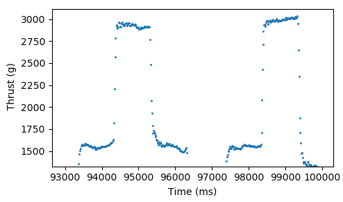
This mode still needs some finessing in terms of usability as it currently relies upon the user to change the throttle step inputs within the script.
Output Data and Post Processor
The data captured by this script is dumped to a *.CSV file so the bar to entry for processing the data is very accessible. For example, it is easy to use the output in the already existing google sheets expo fitting tool.
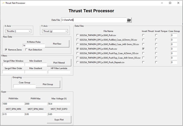
There is not a lot I can say about post-processor at this point as it is very much a moving target and still needs a lot of work. Its functionality so far is:
-
Importing of all *.CSV files in a directory, for comparison.
-
Auto run detection, to split multiple throttle ramp’s from a single file into multiple instances for easy comparison.
-
Plotting of any logged variable against any other variable
-
A number of filters for cleaning data up
-
A crude coax grouping approach that allows you to add different data instances into one net outcome as if it were a coax on test.
-
MOT_THST_EXPO fitting tool
This tool is written in Python and the GUI is done in TKinter. This is what it currently looks like:
About the Thrust Stand Code
The thrust stand code is written in Lua. The code thus far can be found in this WIP PR: #16813
The top section of the code is a port of the C library from SparkFun into LUA, to be able to make use of the NAU7802 amplifiers on the I2C bus. This script therefore uses @IamPete1 's I2C scripting PR (#14276).
The lower section of the script is then the actual thrust stand code.
This script does depend on a few other PRs for scripting bindings before it will work on AP master:
#15857
#16741
#16742
Finally, this PR is marked as WIP at the moment as I am still chasing out one bug, which I don’t believe is actually a fault of this lua script. Basically, I am using a Matek F765. The amplifiers have the same address and are therefore on two seperate I2C busses. For some reason the amplifier for the thrust load cell ‘looses’ data and LUA gets nil values in return. I do have the OLED screen on the same bus, however I have removed this and the problem still occurs. I have also ruled out EMI as both thrust and torque I2C buses are run next to each-other and the fault always occurs on thrust and not torque. Plus both lines are run through a grounded metal braid. Also, I have swapped the thrust and torque amplifiers to rule out a faulty amplifier. This is an intermittent problem so doesn’t always cause issues. Turning down the sampling rate reduces the likely hood of the issue happening, but I am pretty sure thats just because it is reducing the traffic on the bus. I think it might be a race condition or DMA buffer issue, but I am getting well out of my area. So, if anyone has any ideas/pointers on how to debug this I would love to hear them.
Thrust Stand in Use
A video of me using the thrust stand for some 5 inch coax:
Demo of Overcurrent Protection
A video demo of the overcurrent protection functionality. The parameter has been set very low to trigger the protection for the demo.