Using 2 GPS for Yaw: Yaw not available

Hi @Juergen-Fahlbusch, No I am seriously using these connectors. 7A per pin pair, I am having 10 pin pairs for battery so total is 70A. I have been using these for so many months and did not have any issue.

How come will it add a resistance? If I am right then switch will only open and close the circuit, it has some metal strip which is made of the good conductor material. Need to find a good quality switch.

And what is your opinion on using a single 47uF tantalum capacitor?

Thanks again! It has been really great discussing with you and daily learning a lot from you all.

Ohm’s law tells you that each mm of metal does add resistance, small resistance, but resistance nevertheless.

Keep wires short, It reduces weight, reduces interference, increases efficiency, reduces inductance (delay).

2 Likes

As AMILCARLUCAS stated supraconductivity is not really existing on earth. Any switch, also very high quality switches, has a little more resitance as a straight wire of the same length. This rule you can take for all, switches, connectors, solderings …
Also any additional electro mechanical or electronical device is a potential additional point of failure.
It my eyes the best way to solve a problem is to eliminate the root cause as to built a work around.

1 Like

Hi Everyone, How are you all doing? @amilcarlucas @Juergen-Fahlbusch @xfacta

I hope you all are good. Academic stuff were going on so I was little occupied. I will start flying again as soon as possible.

One of my friend is building a small FPV kinda a drone and he asked me some suggestion in placing the electronics to reduce the interference. He is having 4-in-1 ESC, 2.5W VTX, M10QGPS, HMC5883 external compass, radio telemetry and pi zero with 4G module.

I have told him to place VTX and radio telemetry as far as possible to each other. 4G and GPS should be far from each other. Compass and all electronics should be away from the power lines. I have told him to shield the wires of VTX, GPS, 4G and Telemetry. What are your views on this? He is my junior, what else should I tell him?

I am little confused in the antenna placement suggestion, is it important that all antennas (VTX, Tele, and 4G) should be far away from each other?

Thanks! would be waiting for your responses.

Yes, that is all correct.

Yes, all antennas far away from each other is a good policy.

You should further tell him to read and follow the blog post and post a .zip file with his hand edited parameter files.

1 Like

Biggest interference problems:

  • GPS and VTX/Analog camera
  • Compass and lead end of battery

If you tackle those two then the others can usually be managed. Note that cables and connectors can emit just as much RF as antenna, so beware

1 Like

Thanks @amilcarlucas and @andyp1per
Really helpful advice.

Which blog post are you talking about? can you please share the link? Thanks

Yes! I suggested him to keep the VTX under the drone somewhere and GPS will be on top front of the drone. Just wondering why people keep VTX antenna pointing up? Can we keep the VTX antenna facing down? (same like radio receiver) will it degrade the VTX performance?

Yes! I told him to shield the all signal cables. Are you talking about power connectors emitting RF? all power connectors should be far away from the electronics right? and for the power wires, they should be twisted to reduce the magnetic loop area.

Some people in the forum suggest grounding the shielded cables, what is it? I not able to understand it.

And what do you think of shielding the VTX, 4G Module, and other electronics with some aluminum foil or tape? (Not shielding the antennas and GPS). Will it be a good or really bad move? I have seen people shielding the electronics with metal to prevent from other electronic noise.

One last think, How do you guys fix the Matek H743 FC? do you hard mount or use dampers? What will be good choice?

Thanks again! It is really exciting to discuss with you guys and understanding the really amazing things.

Correct shielding needs that the shield is grounded but only on one side of the cable. By this the shield don’t act as wire for the current but has a defined electical potential.
Best shielding is to use directly shielded cables but this is not always easy possible. In this case you can use aluminum foil which you turn close around the cable.
Shielding the electronic in metall chambers is the next step.
But all this is in most specially small and light drones not done.
Make wires as short as possible. Twisting cables also helps Seperate the antennas as already said. GPS looks to the sky so this will be the highest antenna. All other systems will moreless communicate with earth stations so they can be more on the downside of the drone.
Only my oppionion

1 Like

Sure, here it is the link to the Blog post:
Methodically configure and tune ArduCopter

1 Like

Thanks for the response. It is so good to hear from you @Juergen-Fahlbusch sir

means; connecting the shield to the negative terminal of the battery by some wire?

Yes! but he can’t shield all electronics like 4G & Pi. Will flight controller (except compass) be affected by other electronics? If yes! then can you please little elaborate it how? and how good will it be to shield the FC and 4-in-1 ESC?

Yes! this is the first thing I have forwarded to him. Amazing blog post.

Yes! that is a good thing especially in small drones. Can you please share me some photo of the best way to dampen the FC? These are the dampeners available with us (came with FC), Just want to know your choice of FC dampening:
image

Thanks again for your responses. Will be waiting to hear back from you.

If you want to shield a wire than the shield has to be grounded on one side only. This means the shield of this specific wire is grounded nearby the connecting point of this wire. As most wires have connectors so grounding is made if possible direct at this connector by connecting the shield direct to the ground pin on the connector itself if available.
Any electromagnetic fields can have influence on wires. Roughl said the magnitude of this influence is depending to the length of the wire, the field strength of the electromagnitic field and the frequency. So the influence is much greater on the connecting wires as on the electronic boards it self and influence is greater near a transmitting antenna as far away and the influence is greater if the wire length match with wave length.
So going back to the drones if you try to seperate transmitting antennas from receiving antennas as good as possible and use shortest possible twisted wirings this is mostly effective enough in the hobby field

1 Like

Hi @amilcarlucas and @xfacta, I hope you are doing great.

I have started flying again with CUAV Dual GNSS as the UM982 stopped working. I am facing now some other issue. As soon as I take-off my drone, there is something wrong with the GNSS and it shows the error for that: “ekf3 imu0 stopped aiding”

Here is the flight logs: 2024-04-01 18-53-54.bin - Google Drive

Thanks! Really looking forward to your response.

Hello Everyone, I hope you all are doing great. For last few days I have been having so many issues one by one, I guess my drone does not want to fly.

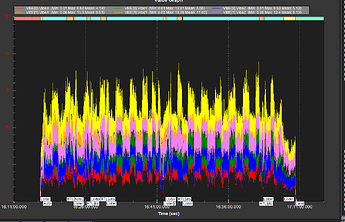
My vibration went from this: (earlier)

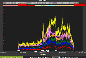
To this: (Now)

Tried my best to level the props and tied all the wires and made sure that nothing is hitting the pixhawk but still there is an unacceptable vibrations in 2nd IMU.

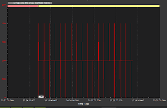
Second Big Issue with the GPS:

Everything was good, I started noticing it in recent flight. I am powering this GPS from a separate reliable BEC (Matek). I don’t thing so that there would be any power issue from the BEC side and already crosscheck all the wires. Everything looks neat and clean.

I am really tired of solving these issues and feel little exhausted. Really need somebody’s advice and help.
Here is the flight log for your reference: 2024-04-07 19-26-36.bin - Google Drive

How many constellations are active on that GNSS receiver?

1 Like

I am using CUAV Dual Antenna GNSS and I have set the GNSS_TYPE to 65 (GPS + GLONASS).

You need to update CUAV 2HP to get proper GPS delta ( refresh rate )

1 Like

Thanks @kalai1219, Do you have any experience with CUAV 2HP? can you please tell me how can I do that? which software shall I use to update it? and my issue is not related to power right? thanks

Hi @amilcarlucas and @xfacta, I hope you are doing great.

Thanks everyone here, I have been flying my drone quite well lately without any problem. I have updated the CUAV firmware and it seems working good now.

From the last few flights, I am noticing that my drone pitch-up and drift back a little while take-off (in some flights, not all). Is it related to the take-off surface?

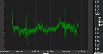
and there is around 4m altitude difference it shows while take-off and land even it take-off and land at the exact same place. Is there anything to worry about it?

Apart from that everything seems good. Just one more thing I want to ask, the second GPS (Holybro M8N) will not properly connect to the satellites near buildings and due to this it shows that Pre arm: Waiting for Terrain Data. Is that a common problem which people have with small GPS? I want to use the second GPS as a fallback GPS in case of 1st GPS fail, How can I do that? is there a way to setup so that?

Here is the logs for your reference: 2024-04-20 13-41-16.bin - Google Drive

Thanks again for your wonderful support, help and suggestions.

An M8N will always have more trouble with multipathing and interference - that is standard.
Try
GPS_AUTO_SWITCH,4
to see if that’s any better than 0

The compass calibrations could be better and is probably what is causing that pitch during takeoff - when current suddenly affects the compasses the most.
Try this from Magfit. Copy/paste into notepad and save as “mag-fix.param” , then load it via the MissionPlanner full parameter list.

COMPASS_OFS_X,-52.995827
COMPASS_OFS_Y,278.07037
COMPASS_OFS_Z,-206.70883
COMPASS_DIA_X,1
COMPASS_DIA_Y,1
COMPASS_DIA_Z,1
COMPASS_ODI_X,0
COMPASS_ODI_Y,0
COMPASS_ODI_Z,0
COMPASS_MOT_X,-4.556727
COMPASS_MOT_Y,6.666737
COMPASS_MOT_Z,-7.154672
COMPASS_SCALE,1.0674402
COMPASS_ORIENT,0
COMPASS_OFS2_X,-162.75343
COMPASS_OFS2_Y,450.83777
COMPASS_OFS2_Z,-82.77387
COMPASS_DIA2_X,1
COMPASS_DIA2_Y,1
COMPASS_DIA2_Z,1
COMPASS_ODI2_X,0
COMPASS_ODI2_Y,0
COMPASS_ODI2_Z,0
COMPASS_MOT2_X,-2.851786
COMPASS_MOT2_Y,11.138788
COMPASS_MOT2_Z,-2.985731
COMPASS_SCALE2,1.062693
COMPASS_ORIENT2,6
COMPASS_OFS3_X,25.7864
COMPASS_OFS3_Y,575.6113
COMPASS_OFS3_Z,-490.3076
COMPASS_DIA3_X,1
COMPASS_DIA3_Y,1
COMPASS_DIA3_Z,1
COMPASS_ODI3_X,0
COMPASS_ODI3_Y,0
COMPASS_ODI3_Z,0
COMPASS_MOT3_X,-7.003119
COMPASS_MOT3_Y,10.638571
COMPASS_MOT3_Z,0.9397366
COMPASS_SCALE3,0.8629868
COMPASS_ORIENT3,0
COMPASS_MOTCT,2
1 Like

Hey @xfacta,
I am facing some issue. It keep on saying: prearm attitude is bad. I have found out the issue, it is because of the GPS based yaw (if I switch the EK3_Src1 source to only compass then this issue will go). I have checked all the connection and parameter, everything is good. It is reporting the GPS Yaw: 165 and does not change even if I rotate the drone with a good sat count and hdop.

Here is the log for your reference: 122 27-04-2024 10-16-16.bin - Google Drive

Thanks!