Many of you may be familiar with MAVExplorer’s MAGFit functionality that allows compass calibrations to be performed from flight logs. Our new tool brings the same functionality to our WebTools suite.
For best results use a flight log that covers as many orientations as possible. Flying figure of eight patterns works well. If you need a motor calibration using either throttle or a current reading then you should also try to cover as wide a range of throttles and current draws as possible. You do not have to be in any particular flight mode.
Once you have a log, load it up in the tool crop out any landed parts at the start and end and hit calculate.
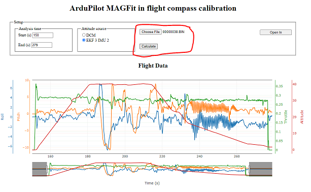
You will then see some information about the compasses found. What type they are, if there selected to use, if there internal or external and if the sensor is healthy (healthy means we have communication with the sensor, not that it is giving good readings). The tool also provides a “Coverage” bar, this represents how many vehicle orientations are present in the log, the higher the coverage the more confidence you can have in the results. It is all possible orientations including upside-down, so your unlikely to get more than 40% unless you flying in acro. This is a example with good coverage:
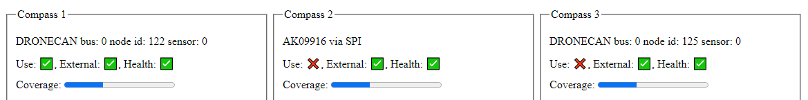
The next set of options allows you to modify parameters in the calibration that will be saved. You can update the compass use parameter. You might want to set a compass to not use if the results are still bad after a calibration or you may find that with the calibration you can start using a compass. By default there will be no use parameter in the saved parameter set.
The orientation options allows the tool to fix incorrect compass orientations. The tool will always check and if it thinks your orientation is incorrect it will alert you with a pop-up warning. If you get this warning you can select either Fix 90 to fix to the best orientation that is a multiple of 90 degrees or Fix 45 to fix to the best that is a multiple of 45 degrees. The orientation check will give a ratio when it gives its warning, the larger this number is the more sure it is.

The final set of options allow you to select which calibrations you want to review. The last selected check box for each compass will be the parameter set which is saved. Existing is the existing calibration that was used in the flight. There are three calibrations done for each motor compensation type. There will always be a “no motor comp” set you will also see a set of calibrations using battery current compensation if there is current data in the log.
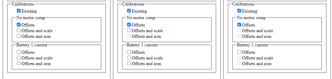
The three calibrations are:
-
Offsets: They account for any X Y Z error in magnetic field reading, a perfect compass in a
perfect vehicle would have zero offsets. However this does not mean a large offset value is bad, there is always some compass manufacturing tolerance and offset due to magnetic materials in the vehicle. Provided they remain constant these calibrated values can cancel out this effect. -
Offsets and scale: This includes the offsets as above but also calibrates the scale parameter. This is a multiplier applied to all axis. This should only be needed to account for manufacturing tolerances in the sensor.
-
Offsets and iorn: This includes the offsets and adds a soft iron correction matrix, as represented in ArduPilot by three diagonal and three off-diagonal values. Iron and other ferromagnetic material can bend magnetic fields. These materials are not magnetic themselves but can be picked up by a magnet. These calibration values allow ArduPilot to compensate for this local bend in the earths magnetic field caused by the vehicle. In the perfect vehicle diagonals would all be one and off diagonals all zero. The iron matrix applies a scale to each axis, so there is no need to also calibrate the dedicated scale parameter.
Motor compensation is used to remove the effect of changing electromagnetic forces caused by the vehicles power wiring. All wires produce a magnetic field proportional to the current running through them. ArduPilot is directly measuring the vehicles current draw (or can estimate from throttle position) this allows the changing magnetic field to be compensated for.
Note that all options may not be available, if an option is grayed out it means that the calibration returned out of range values and cannot be used. This could be because of interference or incorrect orientation. You may find a longer flight with a better coverage of orientations is able to find a valid solution, or you may want to consider moving the compass to a better location on the vehicle.
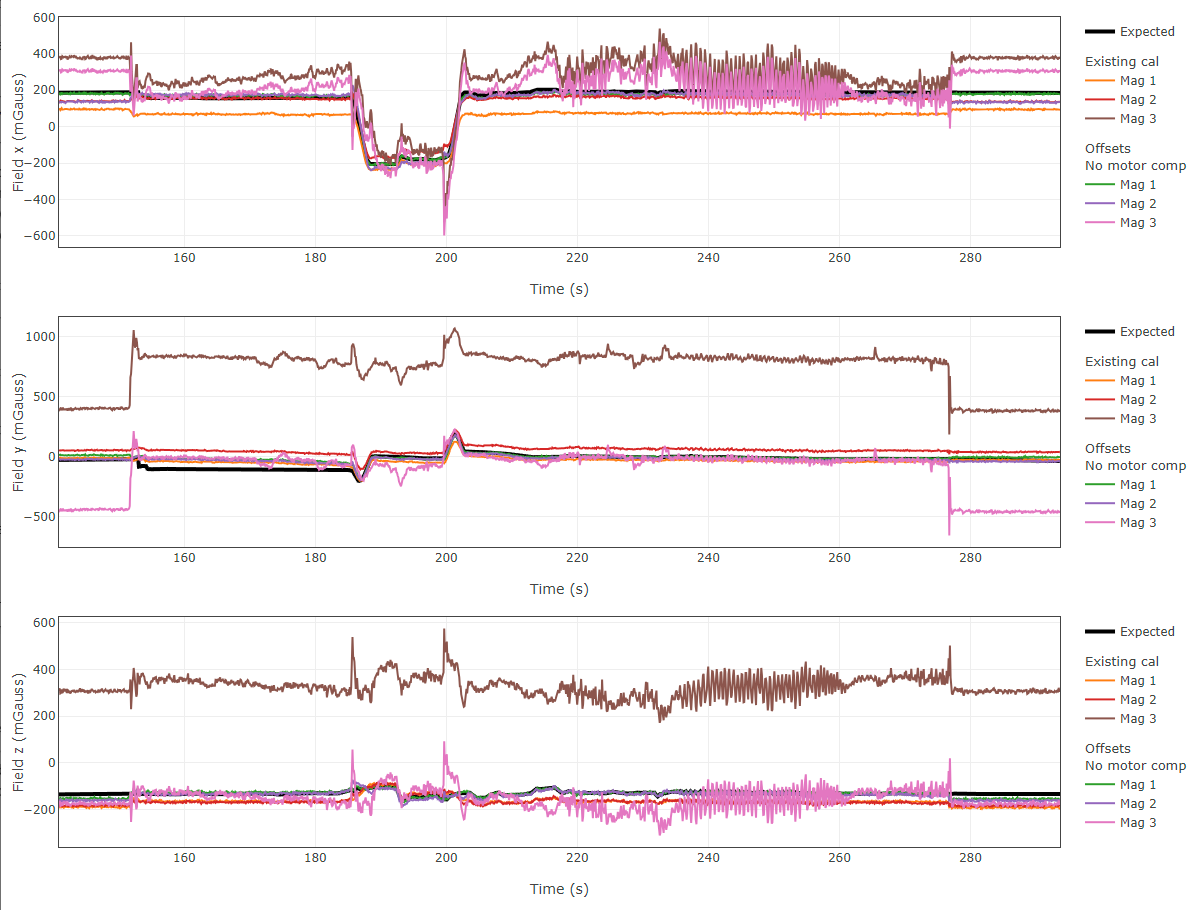
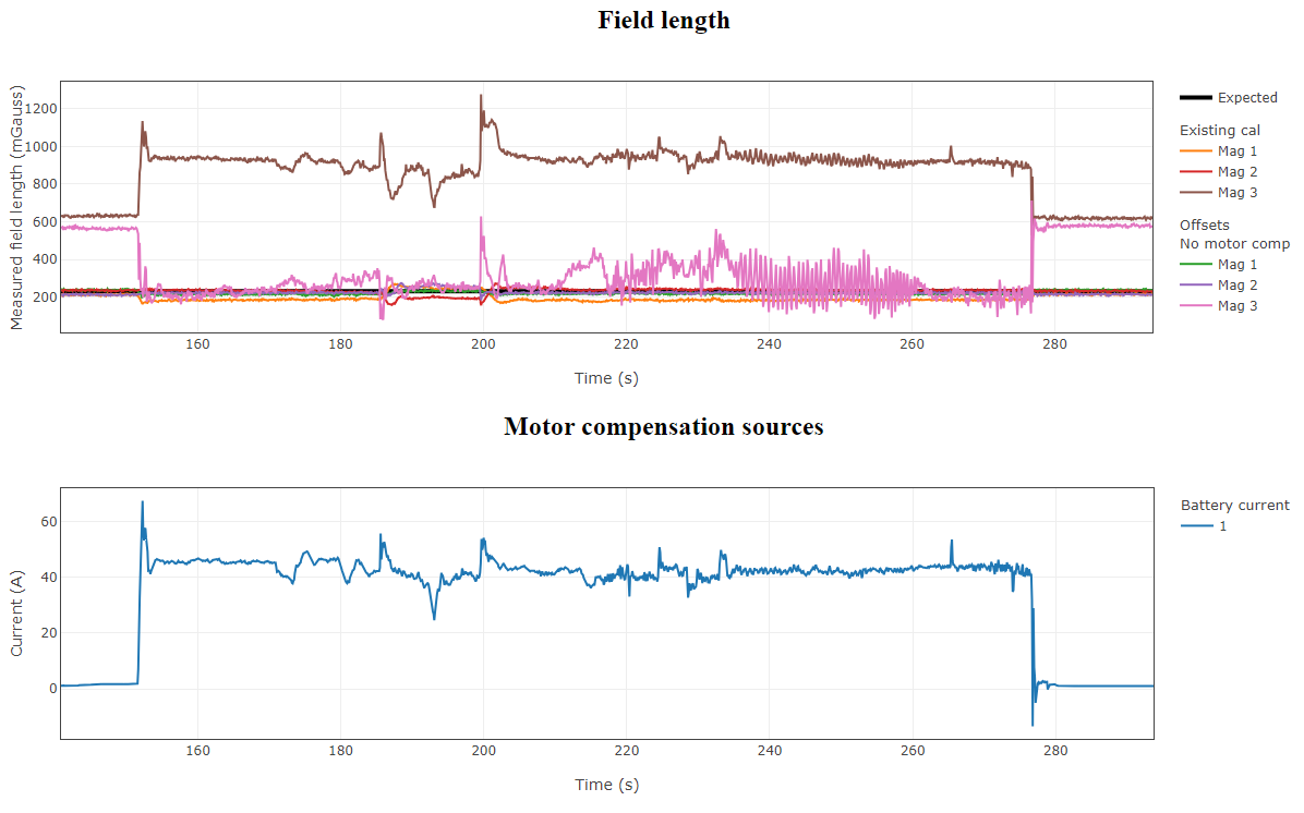
The tool shows the results of the various calibrations in the body frame X Y and Z axis. The black line is the expected magnetic field as calculated from the vehicles attitude and location using the World Magnetic Model (WMM). A perfect calibration would match this expected field strength exactly (if we assume the WMM is also perfect). The calibrations that this tool provides are calculated to minimize the difference between what the sensor reads and what the WMM predicts.
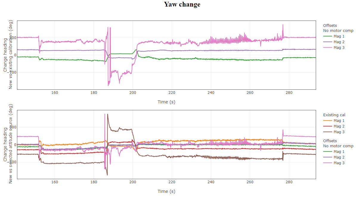
The next set of plots give the change in yaw between the original flight and the yaw from the calibrated compass. The first is the change between the calculated heading using only the compass. Small numbers mean the original calibration is very close to the new one. Large numbers can mean either the new, or the original calibration is bad.
The second plot is the change between the new compass heading and the heading from the selected attitude source during the flight. The EKF is very good a compensating for compass errors so it can get a more accurate heading than the compass alone, this is compared to the heading as calculated from the new calibration. If you did not notice any compass issues in the flight (such as toilet bowling) and there is a large angle change, the new calibration is probably not trustworthy.
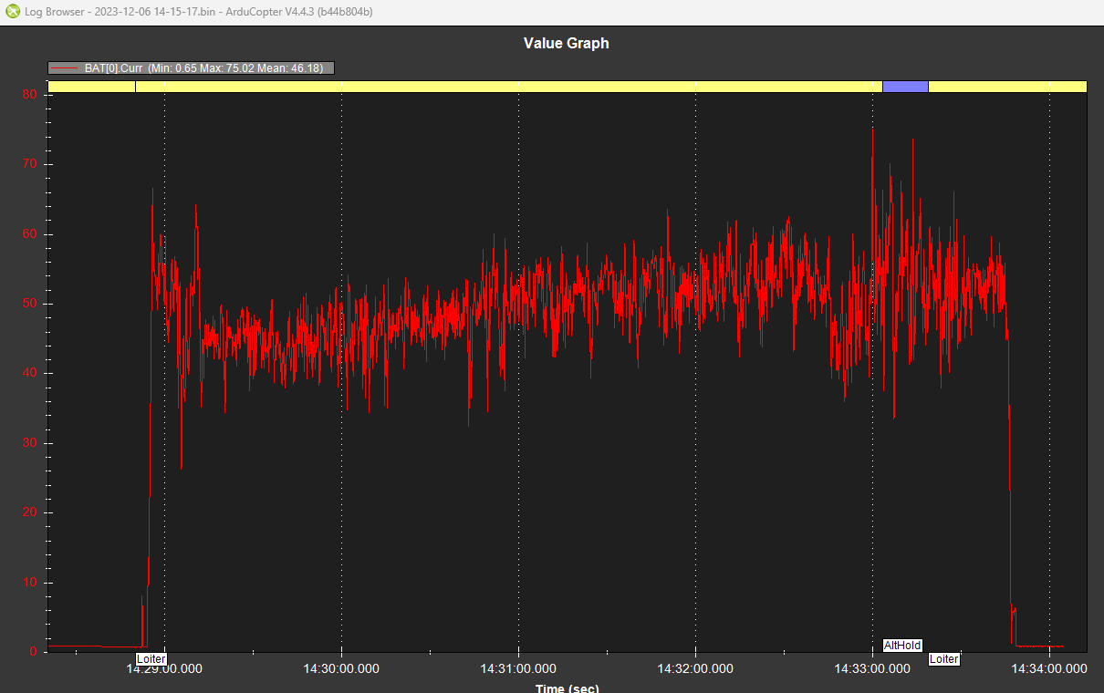
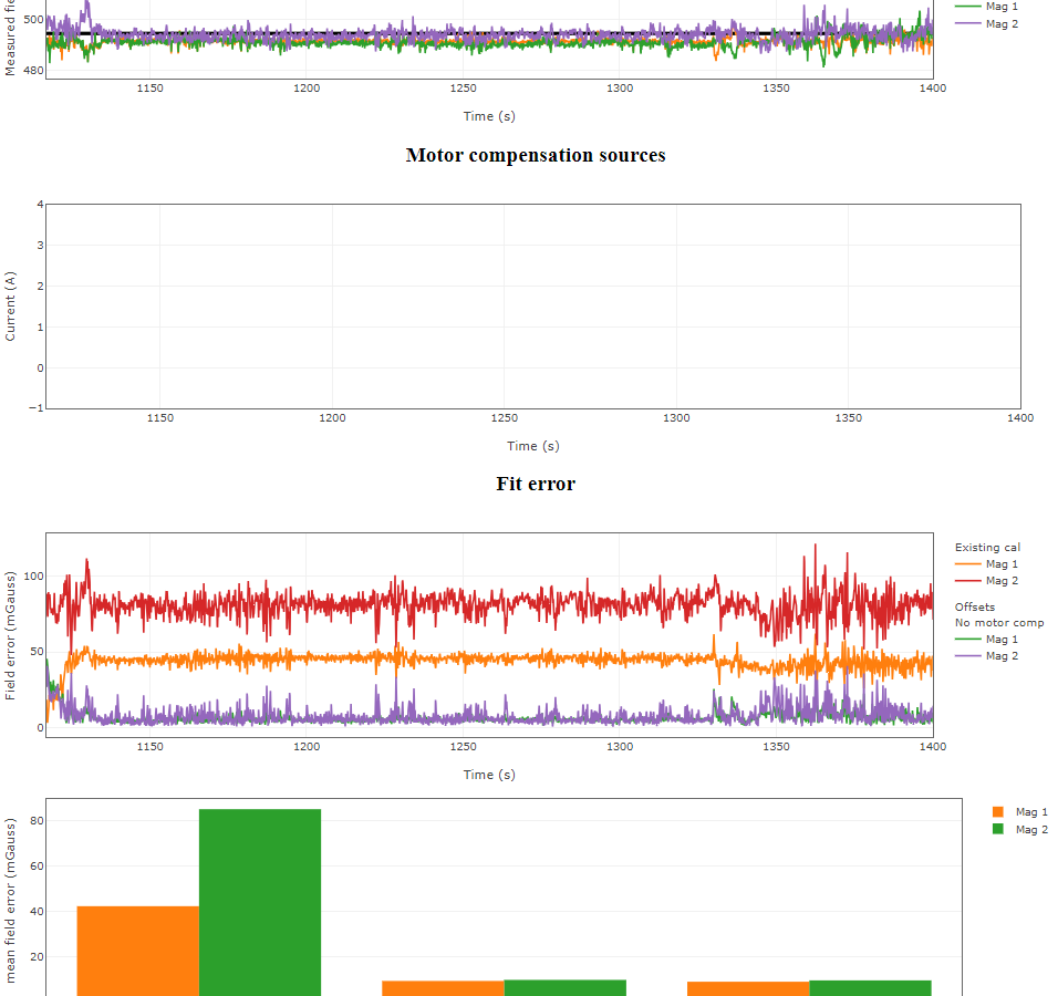
The next two plots are useful for looking for correlation between interference sources and the measured field. The measured field length is plotted against the expected, any external magnetic field will cause the length of the measured field to change, typically this is from the high current draw of the propulsion system. In this example there is a clear link between the measured field of the third compass and the current draw. This is particularly noticeable at the start and end of the flight. If you see this you can try a calibration with battery current compensation, however in this example the results were still quite bad, so the third compass cannot be used on this vehicle.
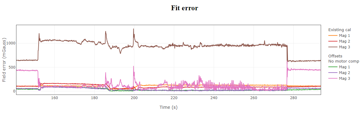
Fit error is the cost function that the tool tries to minimize in order to find the best fit. Again you might see a correlation between the error and the current draw.
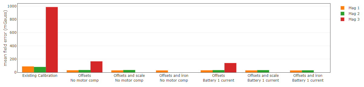
The final plot is a bar graph of all the possible calibration options for each compass. This is the average error from the above plot over the section of the flight selected. This gives a quick way to compare the different fits and to compare between different compasses. For example based on the results shown below it is clear the third compass is not giving good results and should not be used. In the original calibration the second compass was slightly better, however after the MAGFit the first compass gives a better result so in this case the first compass should be the primary.
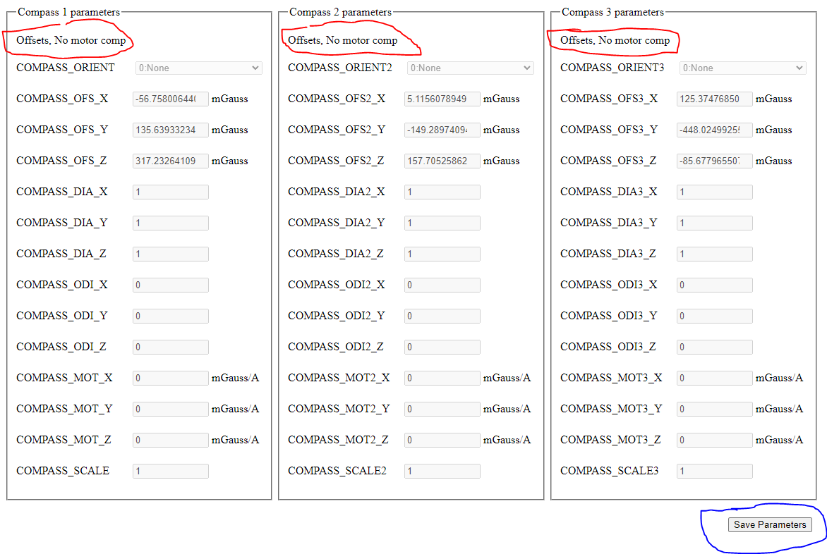
Finally the parameter values calculated are shown along with a save button to download the calibration as a parameter file that can be loaded and saved onto the flight controller. Note that it will tell you which of the calibrations is selected and will be saved. It will also confirm this a second time with a pop-up when you click the save button.
If the save button is grayed out make sure you have hit calculate at the top of the page.
I have done a demo video that shows a few example logs:

The tool is still quite new, if you have any questions or issues please ask here.
Code can be found in our WebTools repository:
Feedback and Pull requests welcome!