A few month ago, I wrote about setting up an avoidance system using affordable 12 Meter Indoor and 6 Meter Outdoor Time of Flight (ToF) rangefinder made by Benewake : the TFMINI.
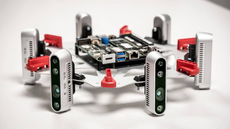
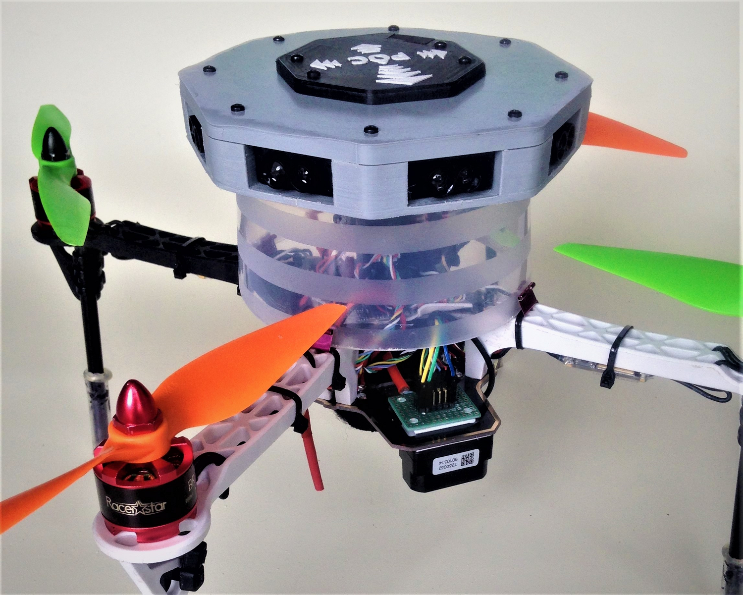
At the time, there was only the serial version available, and in order to add functionality , I used an Arduino to make it talk I2C. Based on this configuration, I decided to push the concept and constructed an avoidance system using up to 10 of these sensors, that I called the POC:
This unit was working quite good as demonstrated indoor and outdoor, and using MavLink message to transfer individual ranges to the avoidance library was straightforward. Unfortunately, the concept of building an additional system using Micro-controllers in order to process the conversion of signals and data to the Flight Controller was a little complicated for many.
Since then, 2 new features have been developed that makes this project more appealing:
A) ArduPilot now offers 8 rangefinder instances that can be directly associated to specific orientations.
B) Benewake has release a new release of the TFMINI that comes in 2 flavors; The TFMINI-S that offers the same size and format and the TFMINI PUS with an enclosure that comply to IP65.
So it is now technically possible to build a POC just by tying the I2C lines of the many TFMini-S together and assign to the desired address the corresponding vector (forward, left, right,…etc.). This is what I am presenting here, a step-by-step instructions on how to configure, test and implement 6 TFMini-S as an avoidance systems.
TFMini-S
http://en.benewake.com/product/detail/5c345e26e5b3a844c472329c.html
TFMini-S has the advantages of low cost, small volume and low power consumption, and multiple interfaces to meet different requirements. The maximum detection distance of TFMini-S is 12 meters. FOV of 2 degrees. Its anti-interference is strong, and can work in outdoor light; the overall weight is 4.7g. TFMini-S LiDAR adopts UART (TTL) / I2C communication interface, can supplied by standard 5V, and its average power consumption is 0.6w.
Programming the unit
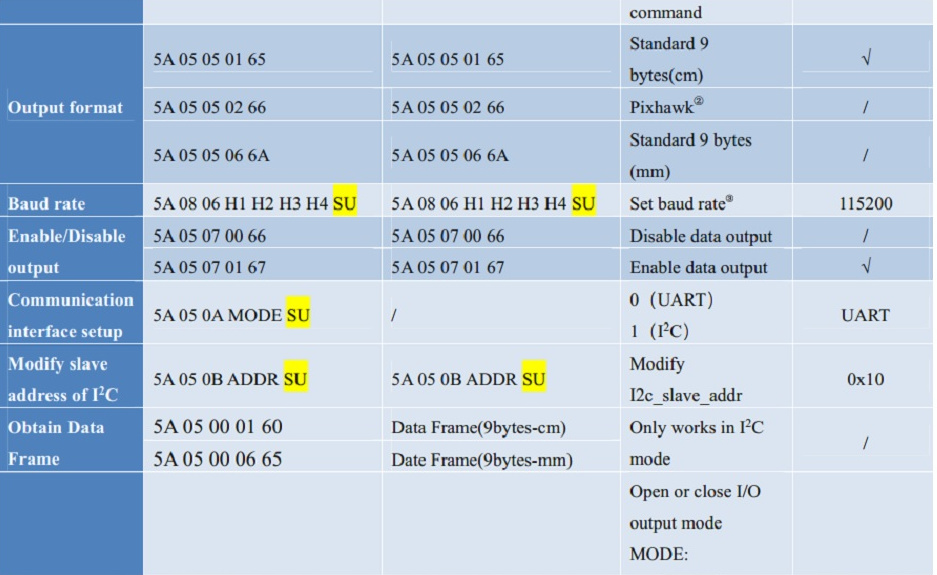
In order to make it work as an avoidance array, we need to set the individual I2C address and switch to I2C mode. From the Manual, we get these commands:
You can interface the unit using a FTDI USB to SERIAL adapter as shown in the next picture below, and using the BeneWake GUI or an advanced terminal software that can send HexaDecimal Strings ( RealTerm). Once connected, you can send these sequence in order to make the TFMini-S work in I2C:
Changing Address
Command: 5A 05 0B address SU
The SU is the checksum of the command, You need to add al the Hex characters in order to get thins number.
To set the TFMini-s to address 11 (10 being the default address)you need to send: 5A 05 0B 11 7B and so on to program the consecutive address of the other units:
5A 05 0B 12 7C
5A 05 0B 13 7D
5A 05 0B 14 7E
5A 05 0B 15 7F
Changing Mode
Command: 5A 05 0A mode SU
You need to issue this command
5A 05 0A 01 6A
Save new config to permanent memory:
5A 04 11 6F
So the complete sequence to set address 11, change mode and save is:
5A 05 0B 11 7B
5A 05 0A 01 6A
5A 04 11 6F
Checking result on Arduino
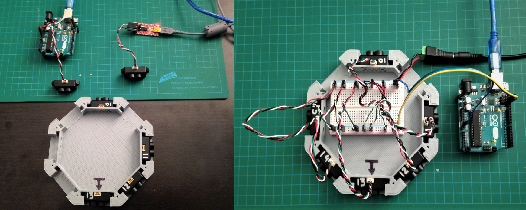
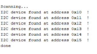
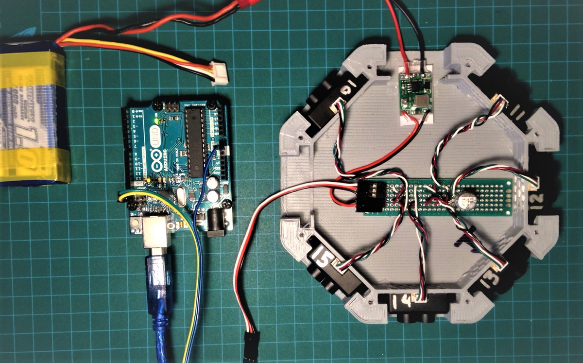
Using a simple code flashed in Arduino UNO, is is easy to check that the programming is correct .Just load the standard program i2c_scanner.ino into your Arduino and connect the power and I2C lines as showed on left.
Picture on left show the FTDI connected to the TFMini-s to be set and the Arduino to check each one and write address with silver marker once confirmed. Picture on right show all the TFMini-s connected to a breadboard with the power lines being fed with external 5 Volts Power supply and data lines connected to Arduino I2C (and ground… important).
You should see this scan result on the monitor screen:
How to bring back the TFMini-Plus configuration to serial
Using the excellent library from Bud Ryerson, https://github.com/budryerson/TFMini-Plus-I2C we can control the parameters of the TFMINI-S using an Arduino
Here is the snipnet of code to switch back the RangeFinder in UART mode:
#include <Wire.h>     // Arduino standard I2C/Two-Wire Library
#include "printf.h"   // Modified by to support Intel based Arduino
#include <TFMPI2C.h>  // TFMini-Plus I2C Library v0.2.2
TFMPI2C tfmP;         // Create a TFMini-Plus I2C object

void setup()
{
    Wire.begin();            // Initialize two-wire interface
    Serial.begin( 115200);   // Initialize terminal serial port
    printf_begin();          // Initialize printf library.
    delay(20);

    printf( "BACK to SERIAL: ");
    if( tfmP.sendCommand( SET_UART_MODE, 0))
    {
        printf( "passed.\r\n");
    }
    else tfmP.printErrorStatus();
}

// = = = = = = = = = =  MAIN LOOP  = = = = = = = = = =
void loop()
{
}
An Arduino is a valuable tool for this type of project. I strongly encourage anyone who want to work with I2C devices to learn how to use an Arduino for test and debug. Most of the libraries that we use in ArduPilot are based on Arduino, this is historically the same build environment and at the time the Arduino was the Pilot…![]()
BUILDING
I added the STL files here for download and print on your favorite 3D machine. I printed this model in PLA using the usual settings. For the interconnection, you can go really easy and use standard Pixhawk I2C Splitter, like these:
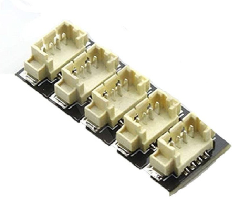
Please note that you may have to swap the SDA-SCL lines for the cable going to the FC.
I did not had them on hand, so I just used the supplied cables and solder them back to back on a small throughole pcb. Added a 3 A ubec and connected using standard servo cables to angled headers. The parts are then fixed with double sided tape and the whole unit is mounted and glued on a plastic stand made of a trimmed down 1$ plastic Lemonade Jug…hey why not ?.. and look at the picture above, it is fixed to the quad using 4 paper clips held with zip ties ![]()
A word on my building philosophy
It may sound ludicrous to build quadcopter with cheap plastic parts but it deserve many purposes in my case. First, most of my builds are experimental, I need to fast assembly and disassembly so having too many screws and attachments is not fun. Experimental means rapid changing of concept and design , in a word ; ephemeral , they don’t exist for long and there is no mean to make them cute, just practical.
Second, just like race cars, they are made to break at the weakest point for crash survivability, hence it is very important to know by design where is the break point. The Lemonade Jug fixed with papers clips is a good example, if I crash during tests, the Jug will easily separate from vehicle and the power cable (standard JST) and data cable (servo connectors) will disconnect without any major impact on the unit I am testing , on this case the POC.

Configure ArduPilot
Based on these wiki:
https://ardupilot.org/dev/docs/code-overview-object-avoidance.html
https://ardupilot.org/dev/docs/code-overview-object-avoidance.html
You can configure the sensors in order to cover as many ‘‘sectors’’ as you want. On my setup I need to cover the full 180 degs. forward and just one sensor looking at the back. In order to do this , you need to assign the individual rangefinder address to the sector it is covering. Referring to the numbers on the sensors at the picture (Hex 10 to 15) here are the corresponding parameters for the configuration within Mission Planner (please note that addressing is decimal in ArduCopter : Hex.10 = Dec 16 and so on):
AVOID_ANGLE_MAX,1000
AVOID_BEHAVE,0
AVOID_DIST_MAX,1
AVOID_ENABLE,2
AVOID_MARGIN,1
PRX_TYPE,4
RNGFND2_ADDR,16
RNGFND2_FUNCTION,0
RNGFND2_GNDCLEAR,10
RNGFND2_MAX_CM,700
RNGFND2_MIN_CM,10
RNGFND2_OFFSET,0
RNGFND2_ORIENT,4
RNGFND2_PIN,-1
RNGFND2_POS_X,0
RNGFND2_POS_Y,0
RNGFND2_POS_Z,0
RNGFND2_PWRRNG,0
RNGFND2_RMETRIC,1
RNGFND2_SCALING,3
RNGFND2_STOP_PIN,-1
RNGFND2_TYPE,25
RNGFND3_ADDR,17
RNGFND3_ORIENT,6
RNGFND3_PIN,-1
RNGFND4_ADDR,18
RNGFND4_ORIENT,7
RNGFND5_ADDR,19
RNGFND5_ORIENT,0
RNGFND6_ADDR,20
RNGFND6_ORIENT,1
RNGFND7_ADDR,21
RNGFND7_ORIENT,2
As for altitude hold, I used the Benewake TFMini PLUS with default setup as UART and connected to SERIAL 3 and configured as:
RNGFND1_ADDR,0
RNGFND1_GNDCLEAR,10
RNGFND1_MAX_CM,700
RNGFND1_MIN_CM,20
RNGFND1_ORIENT,25
RNGFND1_TYPE,20
As for distance, I left the default to 700 cm that is correct for indoor use. By experience, I know that the TFMini has a much shorter range (about 6 Meter) Outdoor in direct sunlight
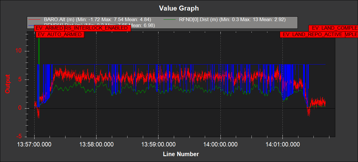
Test with ArduPilot
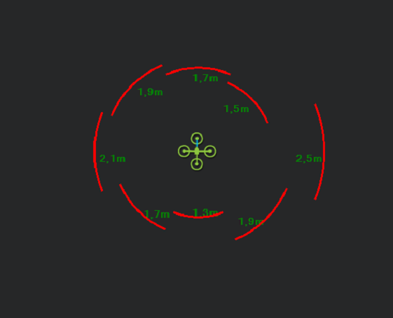
Static test, with the RADAR screen , as explained in the wiki: This window can be opened by going to the Flight Data screen, press Ctrl-F and push the Proximity button. Values will will appear if the PRX_TYPE parameter is set to enable a sensor, and messages are being received.
Make sure that all sectors a reporting correct distance and orientation.
Note when having a single sensor looking backward, as explained in the wiki:
When DISTANCE_SENSOR messages are not received for all 8 sectors, empty sectors are filled in with the distance from an adjacent sector (if available). This conveniently leads to a “cup” shaped fence which is more likely to protect the vehicle from hitting the object. It is likely this will be changed in future releases especially if the “stop” behavior (instead of “slide” behavior) is configured.
This is not a full 360 coverage
The TFMini-s does not cover the totality of the sector as the Field of View (FoV) is 3.6 degs. so it might happen that an object is small enough to be blind to the sensor. This design is for wall following and large surface avoidance.
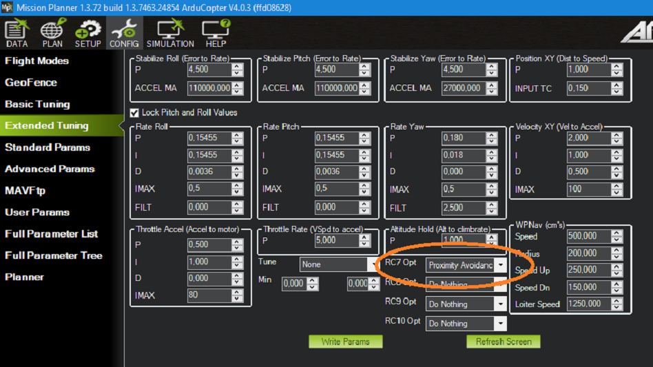
Assign a RC switch to the Avoidance
To enable Avoidance, we need to assign a rc switch to the Avoidance function, in this test I used RC7:
Test Sequence
- Arm
- Takeoff AltHold
- Stabilize and activate avoidance
- Move toward a wall and check the reaction.
Here is a short video showing the initial test in my garage, (you will see that I push the quad toward the door and it bounces back):

More experiments to follow on my channel.
Just hope that this blog can inspire anyone to experiment and progress into more advanced ArduPilot features.
----------------------------UPDATE ------------------ GPS SHIELDING ------------------------
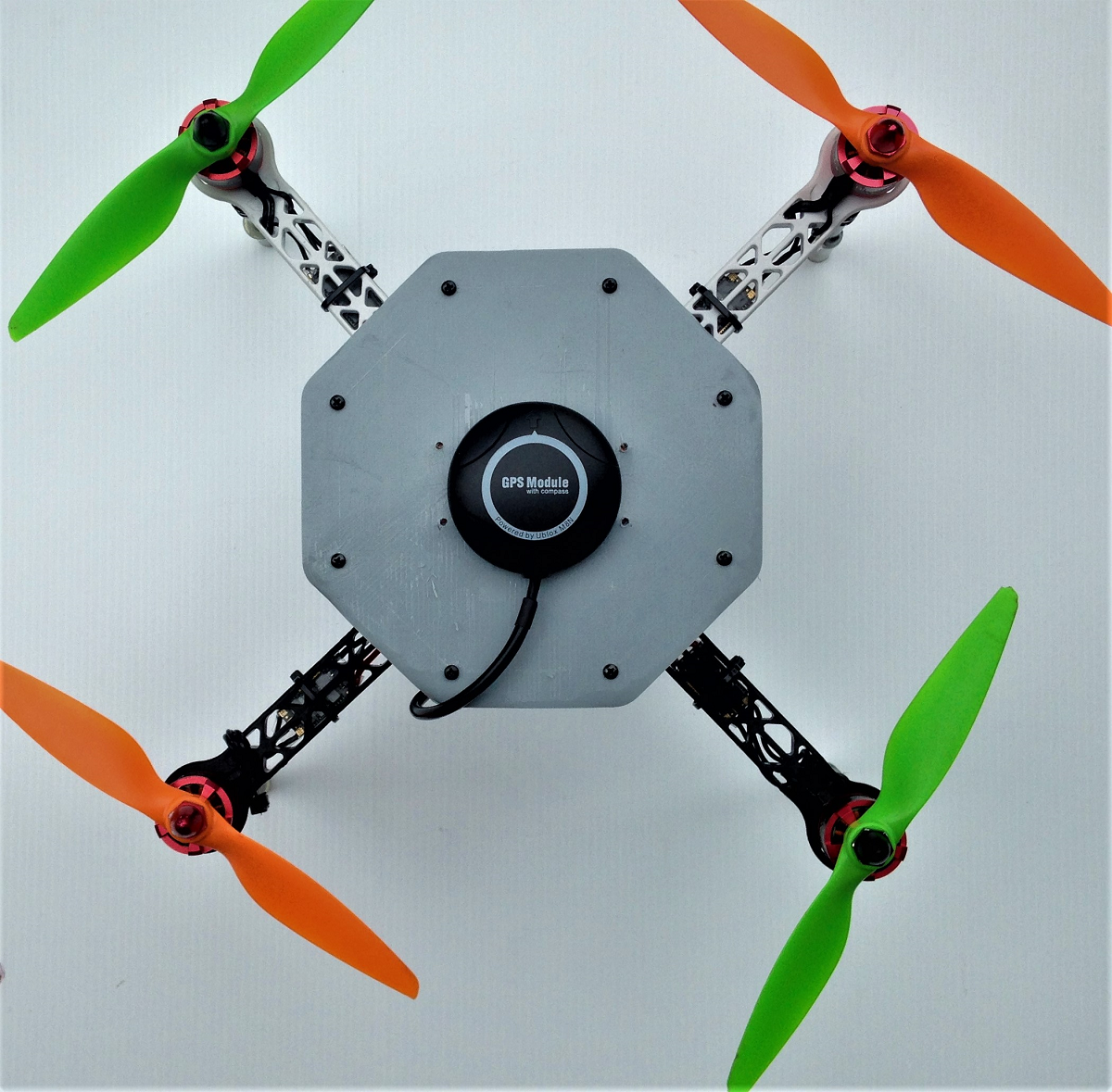
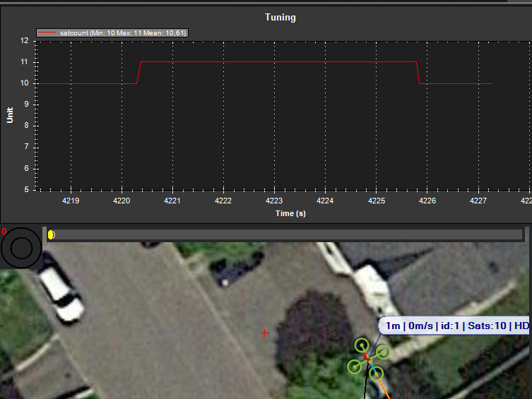
Getting the kit ready for outdoor tests , I installed a GPS on top so it can be tested GUIDED and AUTO.
Unfortunately the GPS (Ublox M8N) could not detect satellites. I hear of some reports that the TFMini could make RF Interference within the GPS Band. So I disconnected the POC and the GPS started detecting Satellites, proving the fact about electromagnetic noise. We need some sort of EMI Shielding, the easiest method is to place the receiver over a Ground Plane so the noise from the rangefinder get lower than the signal from satellites.
Some experiments with NuMetal and Copper (Single Side PC Board) quickly fixed the issue
and a simple fix is to install an octagonal sheet of single side PCB and fix it with hot glue:

Once installed, the signal is quite good , for this type of GPS :
Next step, fly-test and some logs