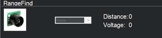
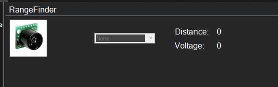
Anyone know why Rangefinder is greyed out. I can see it faintly says none.
But no option to adjust it.
Even if I set the config behind the scenes.
Mission planner build

Anyone know why Rangefinder is greyed out. I can see it faintly says none.
But no option to adjust it.
Even if I set the config behind the scenes.
Mission planner build
Good day, which rangefinder are you using?
TF Mini I2C…but I wouldn’t think the type would make a difference. Mission planner wouldn’t know till I tell it. But then again I could be wrong.
Just use uart port…tf mini is native uart and no i2c
So why is TF Mini I2C rangefinder an option in Mission planner.
Also why would it be greyed out. Mission planner shouldn’t know what version it is until I set it.

So just for giggles I connected a new flight controller with no Rangefinder to see if the box is greyed out and it is.
i2c is if you will change param of it using the ttl key
Sorry I don’t understand what your getting at. Do you mean if you mod the TF Mini in some way. While I agree that there may be config items that need to be done with the mini…this is a mission planner issue. Two different flight controllers one with a rangefinder and one with out both result in a greyed out Rangefiner. This tells me that Mission planner is the issue.
Me im using tf mini plus on uart and can node and work properly
The parameter being called by that MP menu selection probably doesn’t exist. There are other examples of this. You can try the latest Beta Mission Planner, which won’t make any difference in this case, or forget about that menu and configure in the Full Parameter list.
I suspected that was the problem. I wonder what param its looking for,
I will configure it in teh background as soon as I figure out what params need to be set for an I2C version of the TF Mini…thanks all
@rickyg32 just go in mission planner open menu :
configure , full parameter tree and scroll down to rangefinder.
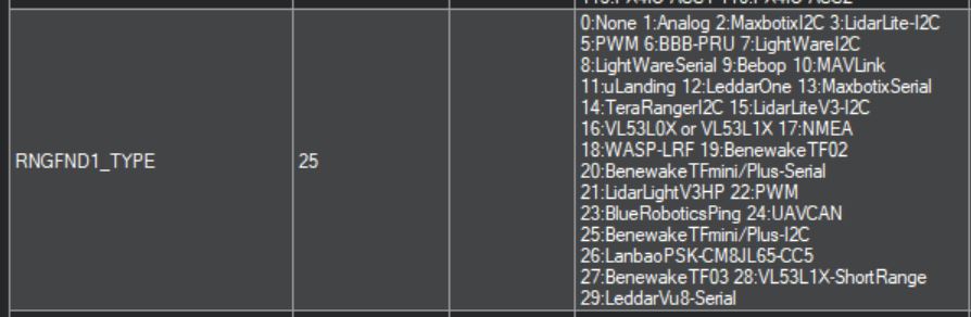
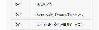
you should set I2C TFMINI as number 25
https://ardupilot.org/copter/docs/parameters.html#rngfnd1-parameters
Tried that and no go…but going to check to see if the cables are connected right.
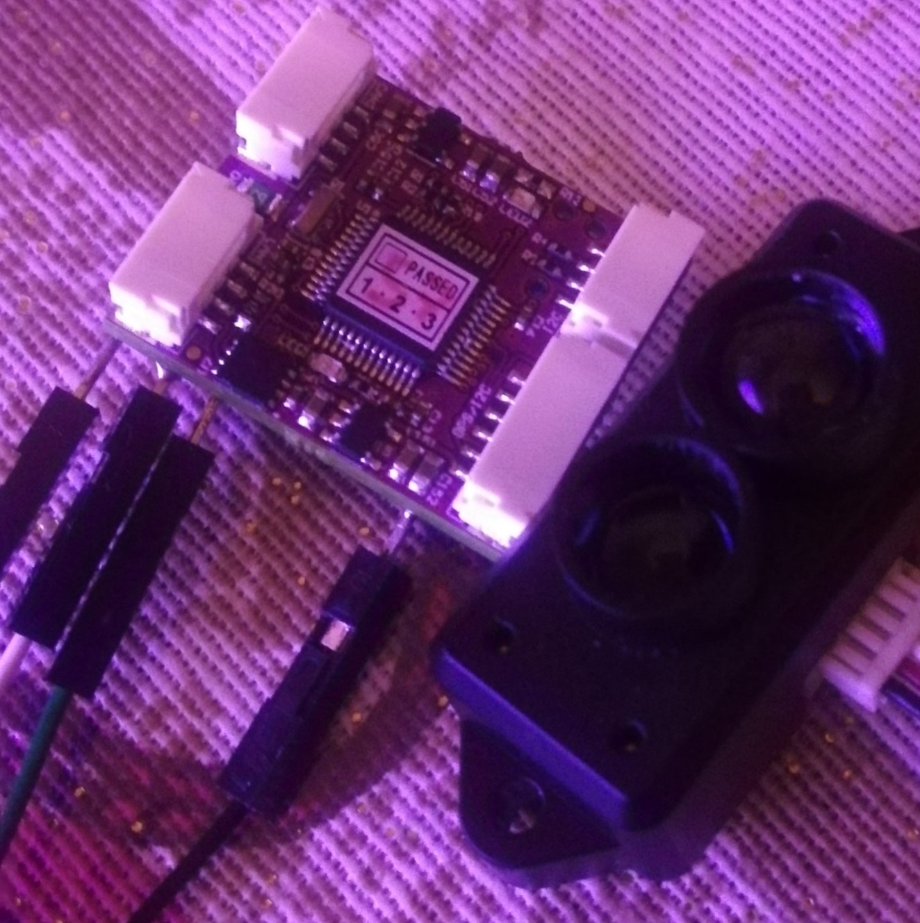
can I get your mission planner settings? Also can you flip that board over and take another pic please?
Good day,
For this application im using mRo Can node f103 flashed with rangefinder firmware.
if you are using the pads under the board you have starting from left:
GND-SDA-SCL-RX2-TX2-RX1-TX1-5V
Solder the black cable to the GND and the power cable to 5V.
Solder the white cable on TX1 pad and the gree n cable on the RX1 pad.
In MP just go to RNGFND1:
RNGFND1_ADDR: 0 (leave in this way)
RNGFND1_ORIENT: 25
RNGFND1_GNDCLEAR: Distance (in cm) from the range finder to the ground ex 5cm to 127
RNGFND1_MIN_CM: me i’ve set 30cm
RNGFND1_MAX_CM: 600
RNFGTYPE: SET IT TO 24(UAVCAN)
I dont have done others modifications.
Lets start can gui settings:
1 CAN_NODE integer 0
2 CAN_BAUDRATE integer 1000000
3 RNGFND_BAUDRATE integer 115200
4 RNGFND1_TYPE integer 20
5 RNGFND1_PIN integer -1
6 RNGFND1_SCALING real 3.0
7 RNGFND1_OFFSET real 0.0
8 RNGFND1_FUNCTION integer 0
9 RNGFND1_MIN_CM integer 30
10 RNGFND1_MAX_CM integer 600
11 RNGFND1_STOP_PIN integer -1
12 RNGFND1_RMETRIC integer 1
13 RNGFND1_PWRRNG integer 0
14 RNGFND1_GNDCLEAR integer 5
15 RNGFND1_ADDR integer 0
16 RNGFND1_POS_X real 0.0
17 RNGFND1_POS_Y real 0.0
18 RNGFND1_POS_Z real 0.0
19 RNGFND1_ORIENT integer 0
After all the settings disconnect the drone from usb…re-strart it
While being really interesting and informative, I do not think that connecting on a UAVCAN gateway is helpfull on the actual problem of @rickyg32 with a TFMINI on I2C… or dod I miss something here ?
Good day on the node you have three I2C options, … on the pads and 2 on top of the boards.
i don’t know which version of tf mini they have,my test is done with the TF mini-S.
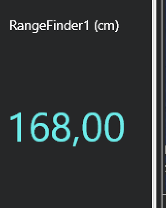
I am not lacking in any ports so there is no need for me to use the UAVCAN port and adapter. However it is interesting to see that it can be done. After doing some reading I found that I had set the Rangefinder type to the serial version. I corrected that to the TFMini I2C and now get the message that the rangerfinder is not detected. So this is a positive step I am now getting an error…But the down side is…Now I am getting an error. I suspect its an addressing issue…but I am unsure what to set it too.
In another document I just found this statement…hmmmm. However in the product manual it makes no statement of TTL only that its I2C.
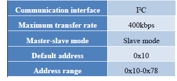
The default communication of TFmini Plus is TTL,IIC and TTL are same cable,so please set TFmini
Plus to IIC communication first,see detail commands in product manual.
Also when I connect my USB to TTL adapter as I did for the UART TFMini there is no data received from the Lidar making me think its really talking I2C.
I connected it direct to the pixhawk bypassing any I2C hubs just to make sure power from the Pix wasn’t a problem…no change.
I really think it’s an address issue but I am at a loss to understand what.
I read in one document to set RNGFND1_ADDR=16 [Address of #1 TFmini Plus in decimal]
But I have no idea if this is correct as the document speaks to using it as a proximity detector for avoidance.
I also confirmed its not a power issue by running the TF on it’s own bec. Pain to setup but I did it…no change.
his is the address which i believe is 16 if I convert it from hex to decimal.
If it is speaking I2C you won’t be able to use the TTL converter.
However check out https://github.com/budryerson/TFMini-Plus-I2C He has done a lot of work with the TFmini’s and arduino. If you have a spare arduino laying around you could load up his INO and scan the bus to see if you can see the mini along with the distance scanning it is doing