Avoidance Experiments with the POC and Benewake TFMINI

Ahhh… Winter in Canada …
While the kids play hockey outside with sticks and a puck , I play inside with sticks and a POC !!

A few month ago I started experimenting with the Avoidance Library:
http://ardupilot.org/dev/docs/code-overview-object-avoidance.html

And I designed The POC : Proximity Obstacle Collision avoidance system based on an Arduino Pro Mini and VL50LX0 TOF rangefinders. This unit works pretty well, the only drawback is that it is shortsighted. This inexpensive Laser device is limited to a range of 1,7 Meter and it makes it hard to implement a fully functional Avoidance System.

Then came the Benewake TFMINI RangeFinder, that offers indoor range up to 12 Meter (6M Outdoor) for a price that makes the POC concept a reality. Some of you might have seen a previous Blog explaining how to make this RangeFinder talk I2C with the use of an Arduino:

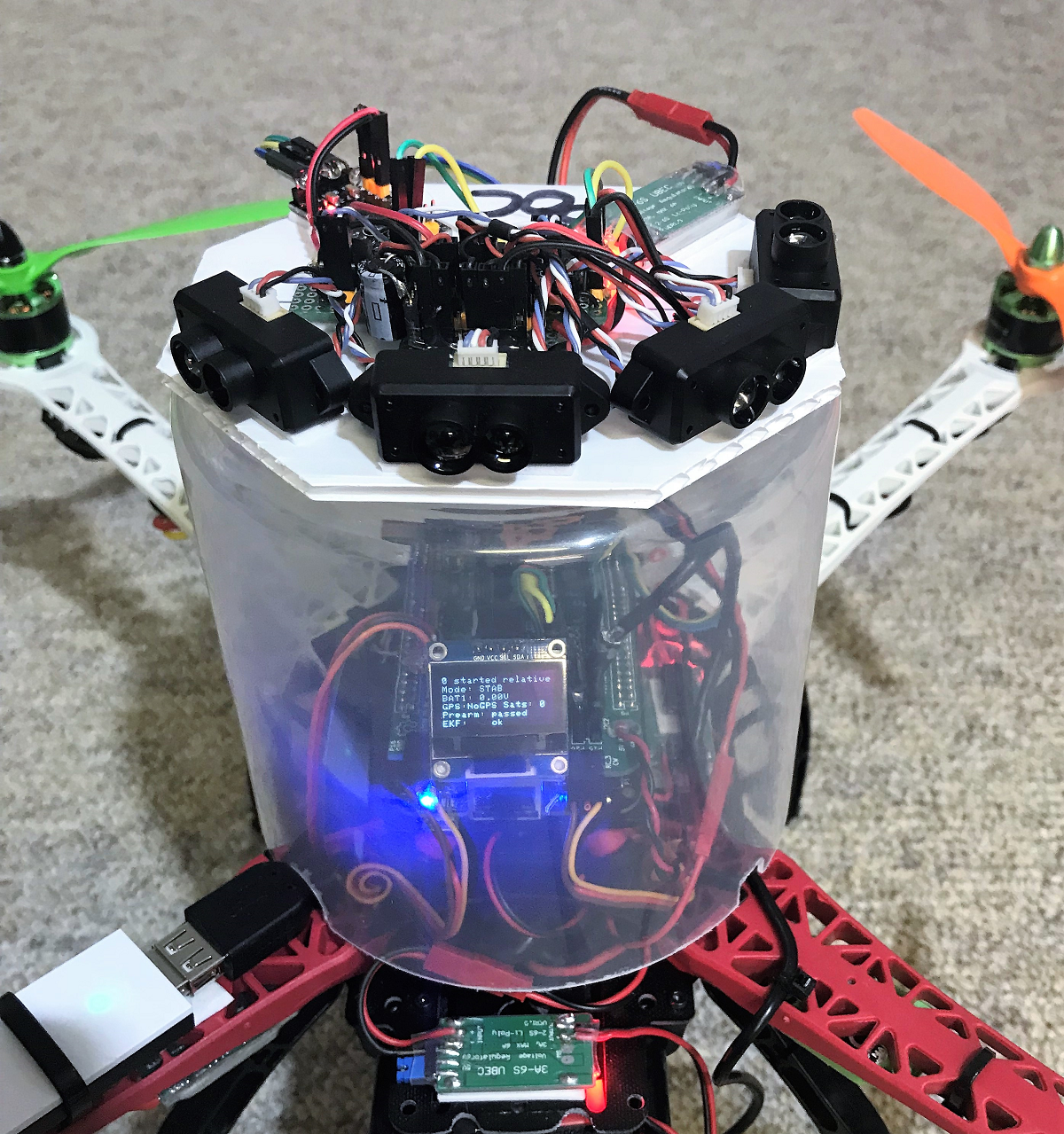
Configuration of the TFMINI-POC:
The actual prototype is using 4 TFMINI
One looking UP
3 Looking @ -45 Forward + 45
TFMINI are Serial devices and its quite difficult to multiplex serial without buffering.
I did some test with a Teensy 3.5 that offers 6 serial ports, but without handshake (hardware or software) its is quite difficult to have a stable unit, that can work in a variety of configuration and speeds (baudrate).

This is why I opted to ‘‘transform’’ the TFMINI into a I2C device. With the Use of Attiny85 we can read the serial flow @ 115200 and do all sorts of signal manipulation and store results in registers, ready to be consumed by the I2C bus. The controler is an Arduino Pro Mini that sequentially read the I2C devices and transmits over serial on a MavLink DISTANCE SENSOR message

https://mavlink.io/en/messages/common.html#DISTANCE_SENSOR

ARDUINO CODE

You can download the code here:

To make a system set the I2C address for each ATtiny and you assign the corresponding vector to the I2C Address:

SETTINGS:
On Mission Planner you set Proximity and Avoidance (as per Avoidnce wiki above) and you can set the avoidance enabling using a transmitter switch, I used ch7 = 40 for Object Avoidance.

And this is how it goes in Alt-Hold Mode:
I use the transmitter to ‘‘push’’ the quad against the garage door and the avoidance system makes it ‘‘bounce’’ back. The harder we push , the harder it bounce back… just like a hockey puck…

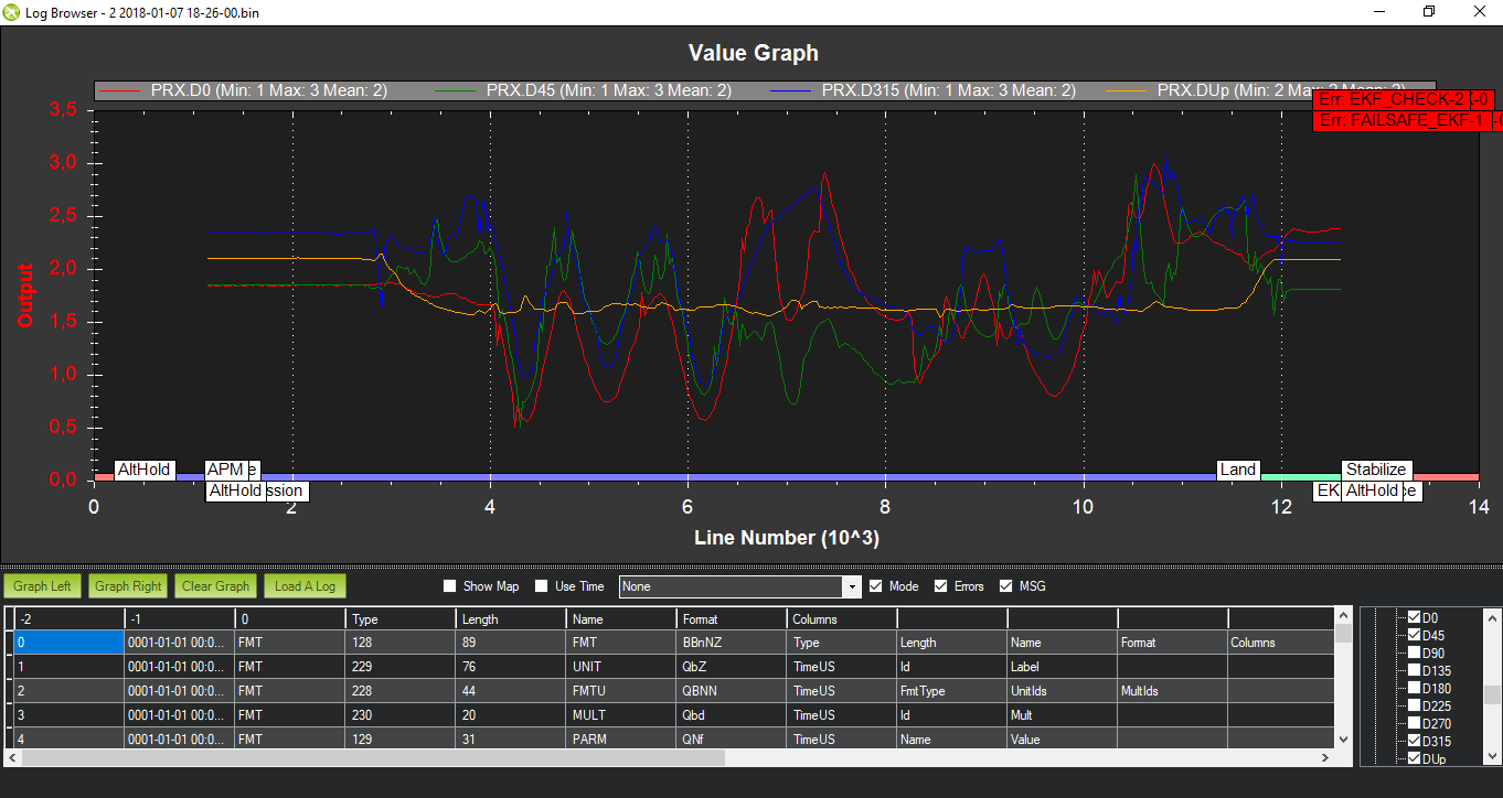
This is how the different signals look on the Logs:

ArduPilot, you blinded me with science…
I would like to thanks the development team and more specifically Randy Mackay for this excellent library that makes me play like a kid in these cold winter days :wink:

To make thing easy , just copy this mavlink file into your Documents/Arduino/libraries
mavlink.zip (623.9 KB)

23 Likes

I will probably make a 3D printed enclosure for the TFMINI - Just like I did for the initial POC

1 Like

Thanks for another excellent article @ppoirier

So, I believe we should encourage you to go live on the North Pole to keep you happy and productive :joy:

1 Like

thanks. one interesting and useful article.

1 Like

Hello, good work ! , what is the electronic card or chip used to convert signal sensor uart to i2c ?

@Tarek-H Thanks

As written in the text , I am using Attiny85 and if you look at the 3rd picture, you can see the 4 DIP chips mounted in row.

Hi, Does it work only Alt Hold mode? Can it use with px4flow and still have avoidance system in loiter mode?

Hello, yes you can fly in loiter using opticalflow.

@ppoirier Thanks for the work done on the TFMini! I was an early buyer and ran into trouble until I followed your posts.

Given lack of documentation, I have been pilfering through code and discussion for better understanding. I really want to try and get examples of the TFMini POC and the VL53 up and running. I have most of what I need except the ATTinys’.

It appears you are using pins 2 and 3 on the ATTiny for RX and TX, and pins 7 and 5 for SCL and SDA to the ProMini, correct? For the most part, everything else looks pretty clear.

As for the VL53L0X setup, I don’t know where else to post questions to. If there is a dedicated thread for it please point where for any future questions.

I read through whatever documentation I could find on how you set this up, but I am left with a couple of questions.

Is the setup running on two different arduino boards, Mega for Mavlink distance messages and Mini for setting ID/addresses via xshunt pin? I see what appear to be .ino files for both.

Is there a photo or diagram for your setup showing where each sensors xshunt pin corresponds to on the Mini?

These are the only things I am really unclear on before attempting to set one up.

You can have more info here: https://github.com/ArduPilot/ardupilot/issues/5605
Basically all you need to know is in the code
https://github.com/patrickpoirier51/POC/blob/master/VL53_MULTI_PROMINI.ino

This code is pretty simple and you can see the shunt pins and the VL53L0X addressing here:

//#define XSHUT_pin6 A7 //not required for address change
//#define XSHUT_pin5 A6
#define XSHUT_pin4 A3
#define XSHUT_pin3 A2
#define XSHUT_pin2 A1
#define XSHUT_pin1 A0

//ADDRESS_DEFAULT 0b0101001 or 41
//#define Sensor1_newAddress 41 not required address change
#define Sensor2_newAddress 42
#define Sensor3_newAddress 43
#define Sensor4_newAddress 44
#define Sensor5_newAddress 45
#define Sensor6_newAddress 46

1 Like

I knew I was a bit rusty on Arduino IDE, but I had no idea. After updating the IDE, all my libraries and spending a couple of days reading through a myriad of discussions, I was finally able to compile basically everything in your repo for obstacle avoidance.

If this goes into the wiki it could certainly use some further elaborating on in regards to the Mavlink libraries and header files for the novice programmer.

Once I get everything wired up and running I will post my results for anyone else who may be interested.

Thanks for everything you have contributed on this so far!

@cthill24 good to know, and Yes , you can share your results so other can benefit

Sorry for my ignorance, but I still don’t know how to I have to do it to connect my sonars Maxbotix I2CXL EZ4 to the Pixhawk (collision avoidance system). Should I connect them to an arduino board and use your code TFMINI_I2C_Mavlink to send the DISTANCE_SENSOR message to the pixhawk? But then how I connect the arduino to the Pixhawk?

Again, sorry for my ignorance, I am quite new in this world. Thank you so much for your time.

Well, look at google for arduino experiments with sonar, experiment with it and when you you gain experience, you could probably try to adapt this experiment Basic Obstacle Stop System-Build Log and firmware

Hey,

I am trying to do a similar project but instead of the TFMINI I am using Maxbotix I2CXL sonars and instead of an Arduino Mini Pro I am using an Arduino UNO. Once the Arduino UNO is ready to send the Mavlink DISTANCE_SENSOR message, how should I connect it to the Pixhawk?

Thank you,

Deepansh

Its connected using serial port and you set the PixHawk port to Mavlink with 115k baud

Thanks a lot again, you are helping me alot.
But I still have not clear which would be the “wire diagram”. Which “pin out” of the Arduino should connect the Serial port of the Pixhawk?

Hi Mister Poirier,

Thank you for sharing your beautiful POC. Before building mine, i have a question about the baudrate in the Attiny sketch : if I understand TFMini connect to Attiny85 by serial with bRate = 115200. But in the sketch (line 60) mySerial.begin(9600). Should I change to 115200?

Merci!

Hello
Yes you can change the speed to 115200.
The reason I changed the TFMINI speed to 9600 (Using the TFMINI speed setting commands) is to reduce the risk of data overruns because there is no buffer on the SoftwareSerial.h

Oh I see. I’m waiting for my 5 TFMINI ordered yesterday.
Thank you