I’m new to this community even if I have already spent many hours reading
I’m trying to feed my copter with 4 distance messages mesured from 4 TFMini plus sensors configured to work with I2C.
I didn’t find any way to configure multiple I2C lidar sensors (each one in a different direction) neither a driver compliant with arducopter, so I imagined the workaround: An arduino (or teensy) connected to a pixhawk telemetry port.
=> The arduino collects the TFmini plus values on the I2C bus ( DONE ! I can plot the 4 distances on the I2C bus. I can give the code if someone is interested)
=> MissionPlanner should display the distances in the RADAR type window
I have integrated the mavlink 2 library to the arduino project:
- “https://mavlink.io/en/messages/common.html#DISTANCE_SENSOR” provides the data structure to be filled
- the “mavlink_msg_distance_sensor_pack” function and “mavlink_msg_to_send_buffer” should allow to send what I need to send.
I have validated I can receive telemetry from the FC to the arduino, but is there a way to log if my messages are correctly received by the FC? (RADAR window don’t display anything )
Yes, the choose of the sensor has been inspired by your project, but with the new generation of TFMini plus which can be configured to work in I2C. The next step should be to (understand how to and) develop a driver directly to be run by ardupilot and the pixhawk I2C port.
Did you find a way to get a trace of the messages you send?
Do the RADAR window shows the proximity values in stabilize mode not armed?
Yes, you need to CTRL-F and choose proximity in mission planner
You can look at proximity message as well in MavLink inspector (on the same CTRL-F screen) but is is not easy to read as the different vectors values keep on changing
Hello,
When I look proximity in mission planner, it gives me the utrasonic rangefinder value in the proximity field. I found good values with QgroundControl.
For the TFmini plus, Benewake has provided a corrective update for the sensor’s firmware for I2C protocol (I had issues). Now I only have to merge the sensor script and the mavlink script.
For the next step, I have no idea how I could integrate & compile directly a new driver into the pixhawk firmware.
@lucasdemarchi, I just find in github ardupilot sources, you did a driver for TFmini plus I2C in the AP_RangeFinder lib, do you know if it’s usable for multiple sensors? (2 TFMini plus in front, 2 on the sides, 1 back, each one configured and tested to work in I2C and all with the new firmware 02.00.03)
thanks!
Community means that everyone is involved in testing, maintaining and updating the wiki… including YOU , so once you make it work correctly, it would be appreciated that you update the wiki with the TFMiniPlus, that is a new breed of the TFMini.
At the bottom of each wiki there is a link for issues or suggestions
Questions, issues, and suggestions about this page can be raised on the forums. Issues and suggestions may be posted on the forums or the Github Issue Tracker.
Simply use it and a wiki maintainer will take care of it
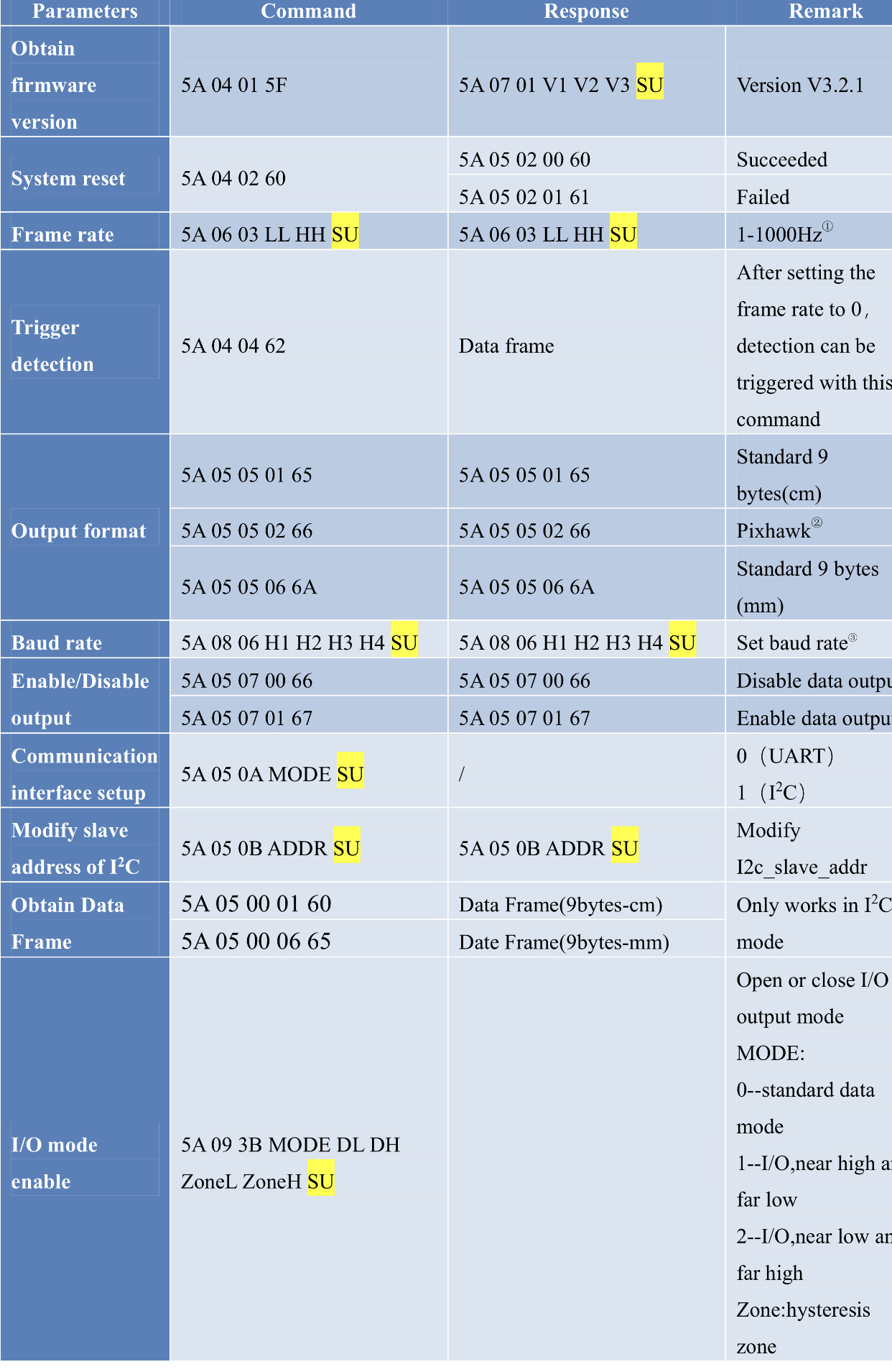
Hi there! I have not gone forward with the use of TFmini plus but I noticed one thing: message for data request is different in I²c than UART:
In AP_RangeFinder_Benewake_TFMiniPlus.cpp from our C++ master @lucasdemarchi , I find " uint8_t CMD_READ_MEASUREMENT[] = { 0x5A, 0x05, 0x00, 0x07, 0x66 }; " which is correct for UART mode, however the correct message for reqesting data on I2C (in centimeter) would be :
CMD_RequestData[]={0x5A, 0x05, 0x00, 0x01,0x60};
(page 18 of the product manual, after having assigned an I2C address, saved, and switched to I2C mode)
After having confirmed the I2C way of running with an arduino nano (in attachement I2C.txt (9.4 KB)), I have tried connecting many tfm+ in I2C on my pixhawk but nothing happened in Mission Planner : No new device or option for assigning a sensor to an avoidance direction.
That’s all I investigated for now… (my baby and my studies are taking all the time )
I have used a TTL to USB adapter to connect each TFM+, you have to choose your sensor and COM port and, if the GUI doesn’t show you any data, that’s surely because your device must be resetted ( “5A 04 02 60” in the “send” area),
Now it should plot measurement data. (you can play with different frequencies…)
After, you have to select an I2C address and calculate the checksum ( I did it in a worksheet exc l) and send it, then save it ( it seems to work also without saving).
Then switch to I2C mode with the Communication interface setup command. (Be warned that after that, any command must be sent in I2C mode! )
Then, with the “Obtain Data Frame” command, you can read the 9 bytes, verify checksum and parse the data.
No need to select PIx mode in I2C mode, if you send the “Obtain Data Frame” command for centimeter , it will send data in centimeter which is the correct format for the Pixhawk
@Slyv06 that means the manual wasn’t updated (yet). I will try to contact them to have it updated. This command I’m using is valid for firmwares 1.7.6 and above.
You will have to get the upgrade tool with Benewake to upgrade the firmware. The upgrade procedure, without swtiching to UART mode is:
1- no need to switch the module to serial port mode (keep it in I2C mode).
2- connect the converter to PC and open the upgrade tool.
3- choose the serial port number and click ‘CONNECT’. Then open the bin file
4- connect the Lidar to the converter. Note: connect only the GND, RX and TX and leave the VCC unconnected at this stage
5- click ‘DOWNLOAD’ on the panel of the upgrade tool and conncet the VCC of the Lidar to the converter within 10s.
Or you switch it to UART mode and then you don’t have to remove the VCC pin.
Also worth noting that depending on the manual version you may have the wrong pin information for I2C. This is the correct one:
Hello @Slyv06 : I would be very interested to look at your code. I am working to get multiple TFmini Plus units talking to a Teensy using i2c. This is for a musical instrument project, but I am very excited about using lidar for it. Thanks!
( ! )

 )
) , so once you make it work correctly, it would be appreciated that you update the wiki with the TFMiniPlus, that is a new breed of the TFMini.
 )
)