Some soldering required

With the launch of an excellent solution by our community member Alex - https://discuss.ardupilot.org/t/an-open-source-frsky-telemetry-script-for-the-taranis-x9d-x9e-and-qx7-radios the interest on building a cheap solution to enable direct FrSky telemetry has grown and the information is quite disperse, so this is to document how to build a small, cheap signal inverter, specifically to be used with regular PixHawk / Cube / Navio 2 flight controllers. Please note that on the PixRacer this is not required because the PixRacer already includes a signal inverter on the telemetry/FrSky port, so only requires a simple cable.

So, what do we want to do? We want to invert a Serial signal from the flight controller and connect that inverted signal to the telemetry port of a FrSky radio receiver.

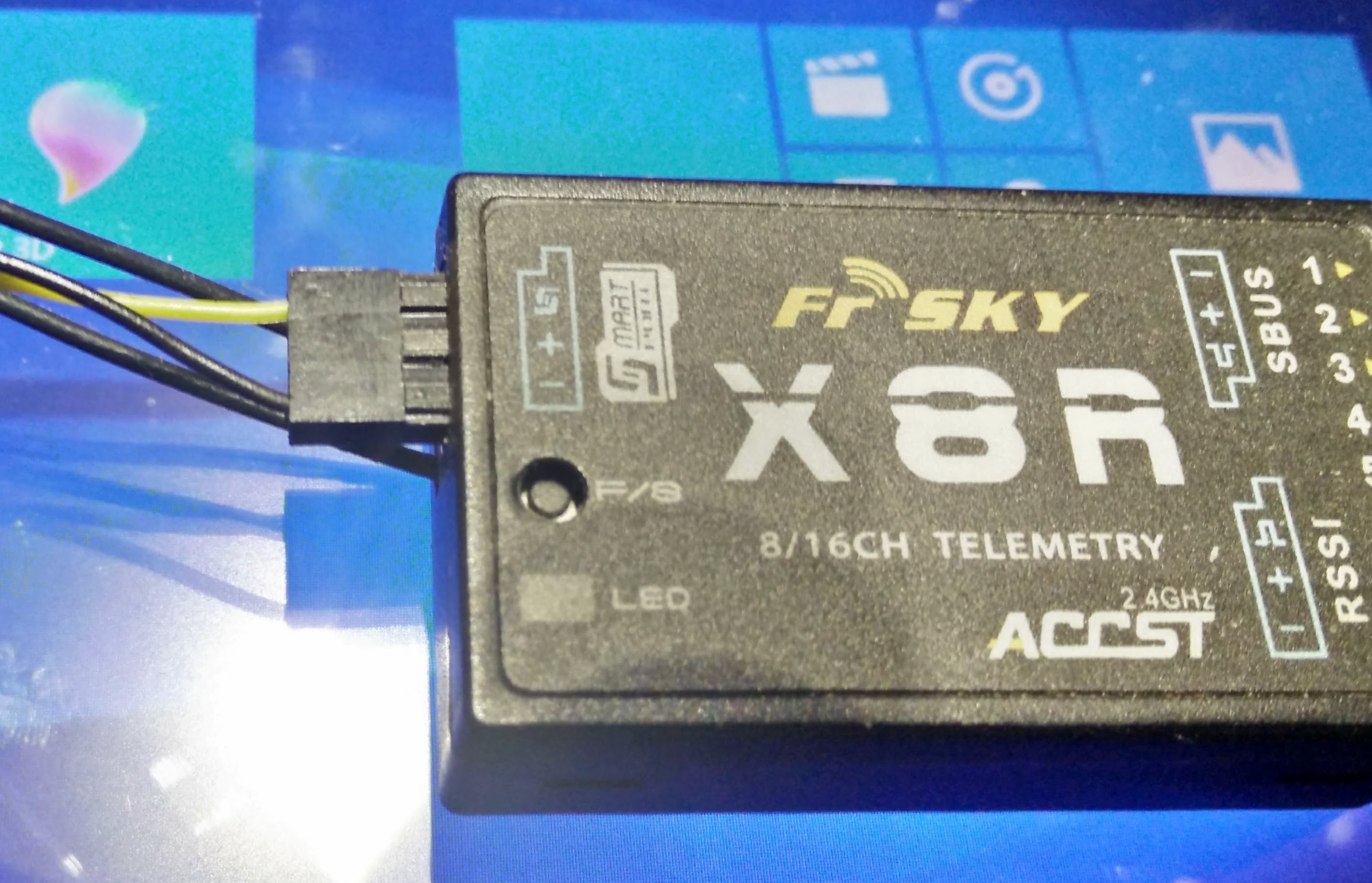
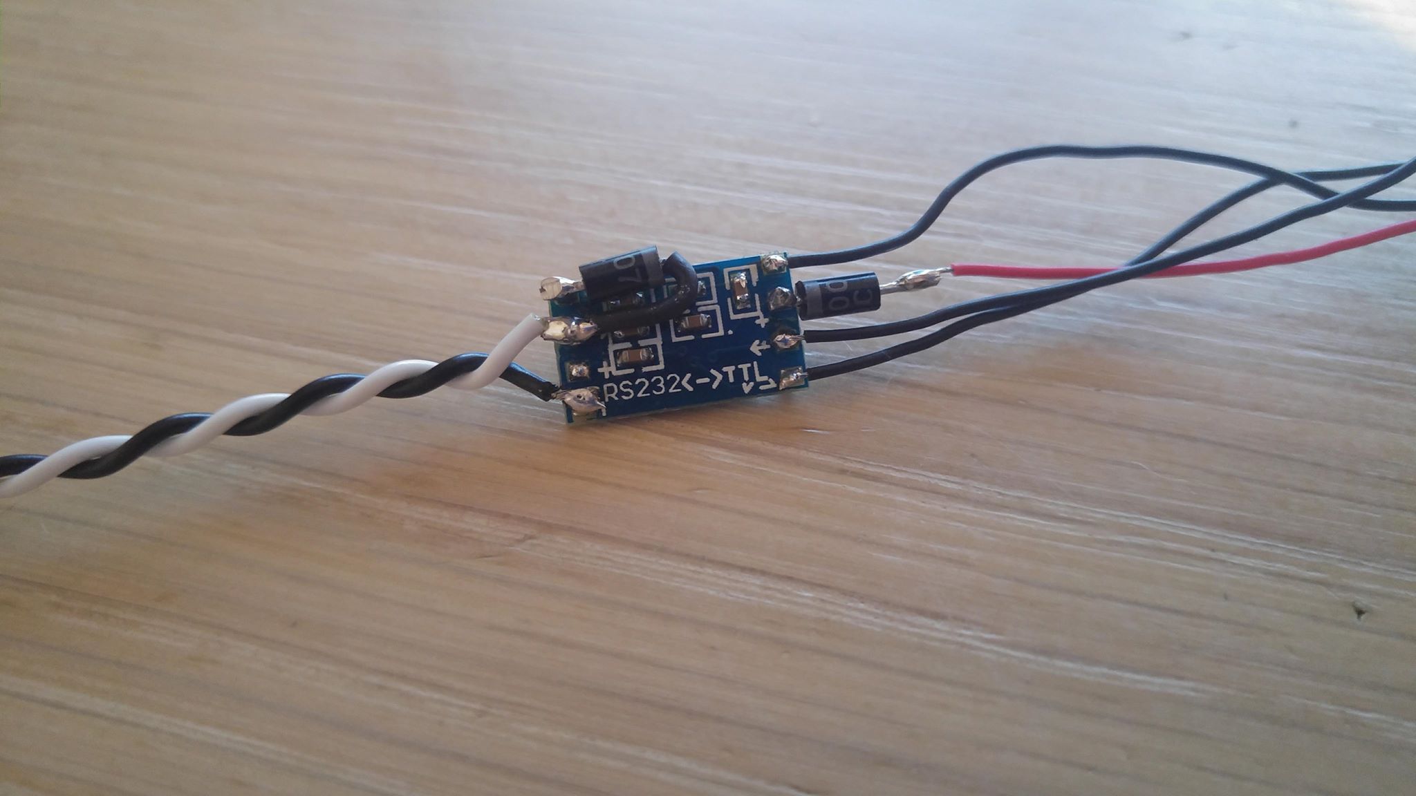
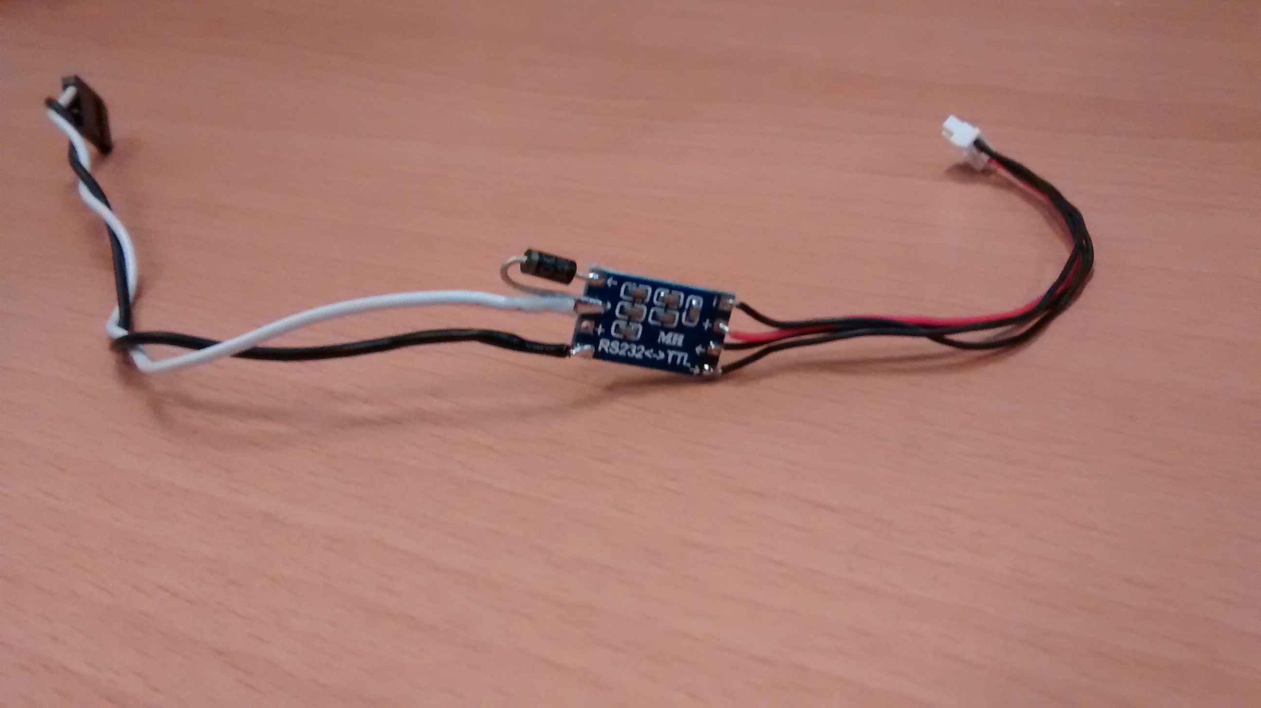
Let’s start with an easy example. A regular PixHawk flight controller, and a X8R radio receiver. For this situation we need the appropriate connectors to use one of the serial ports on the PixHawk (DF13 6 positions) and a regular servo plug to connect on the telemetry port on the X8R. We also need a few additional electronic components. A serial inverter and a small diode. These cost less than 1 USD. I bought mine on ebay.

![IMG_20180404_110135|690x282]

As, you can see, I can build 10 of these for 3.7USD, so parts unit cost so far is 37cents :slight_smile: Let’s add the cost of the plugs and some wire and some heat shrink and our budget of less than 1USD per unit is achieved. Not accounting for labor costs, but, hey… we’re doing this for fun….

Now that the “slow boat from China” has managed to deliver our parts let’s assemble. This requires some soldering, and the usual recommendations regarding soldering very small parts apply.

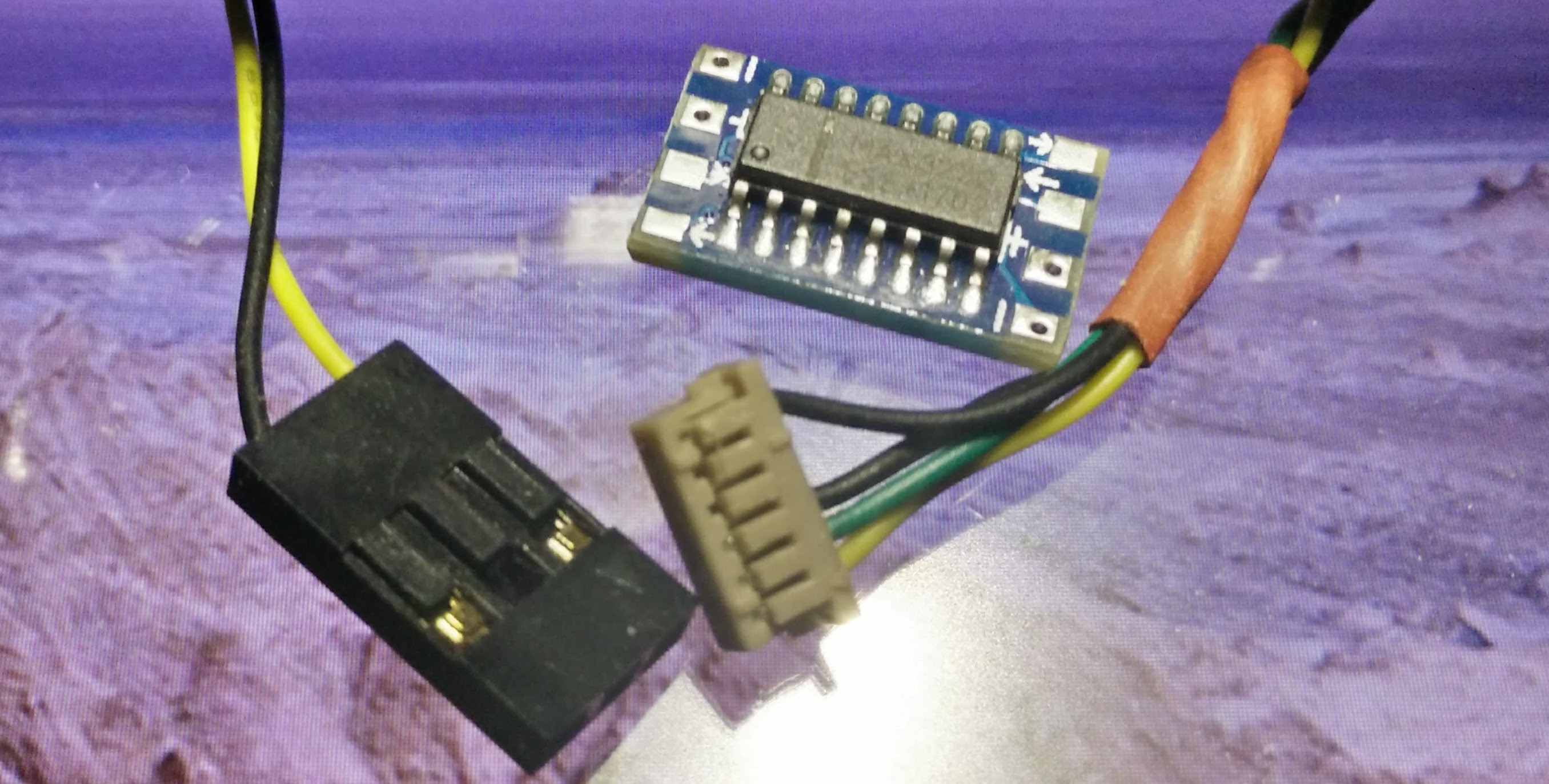
Here you can see the plugs used (the infamous DF13 and the regular servo). Small notes here. The wires on the DF13 are placed for Serial (RX and TX), power and ground, BUT on the servo plug note that we only use the signal and the ground wire

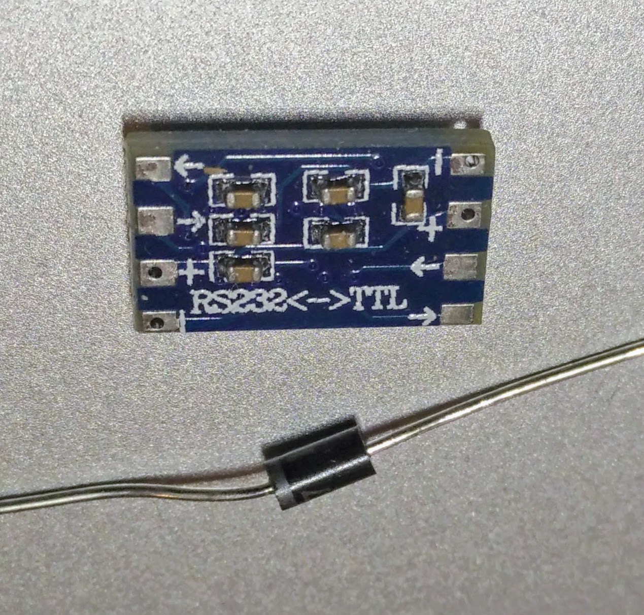
Now we start with some soldering and also how I chose to use the small diode on the back of the small board. (soldering not finished)


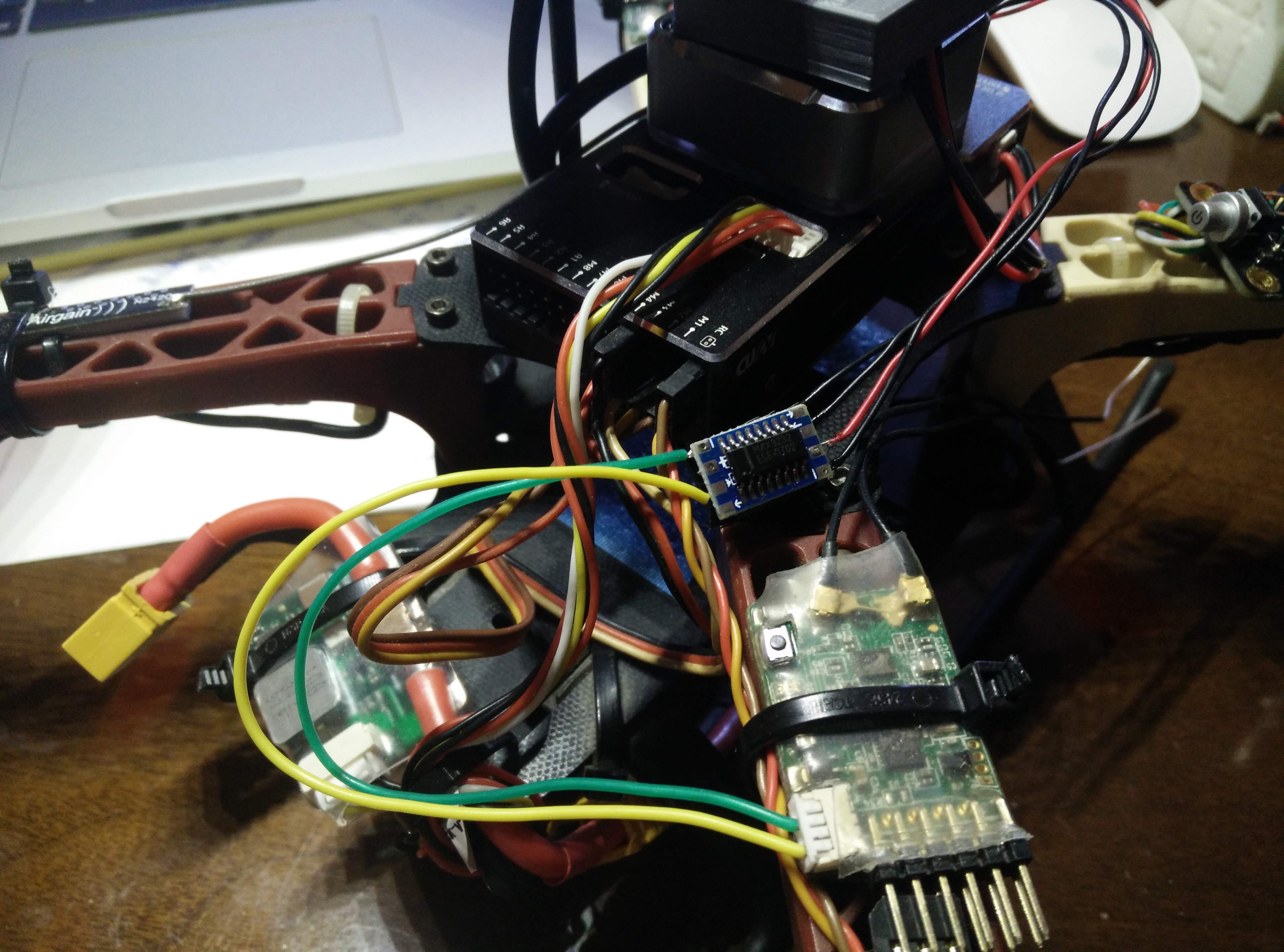
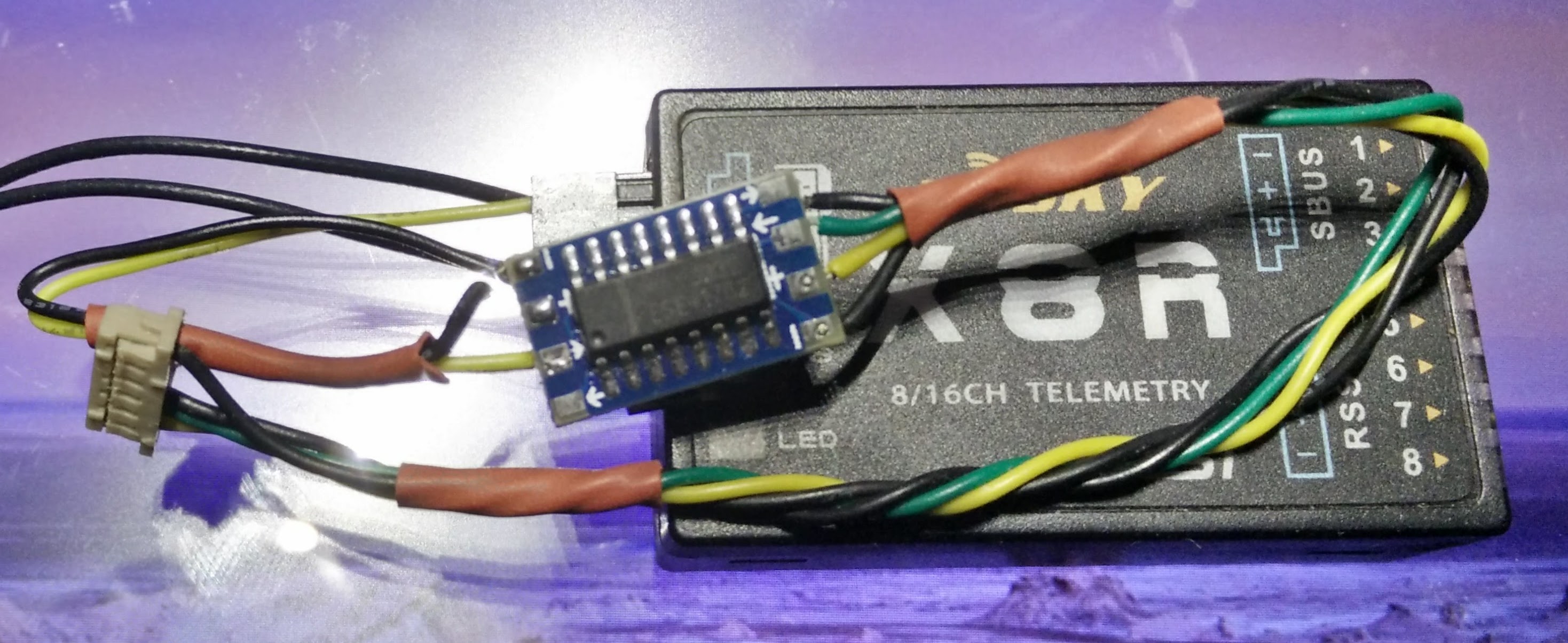
After finishing up all the soldering and “closing” the system with some heat shrink, we can connect to the X8R and to a serial output on the PixHawk (or on Navio2).

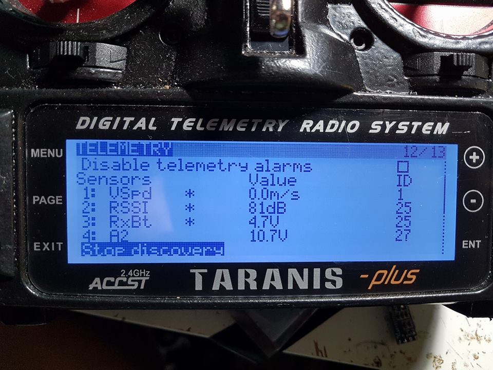
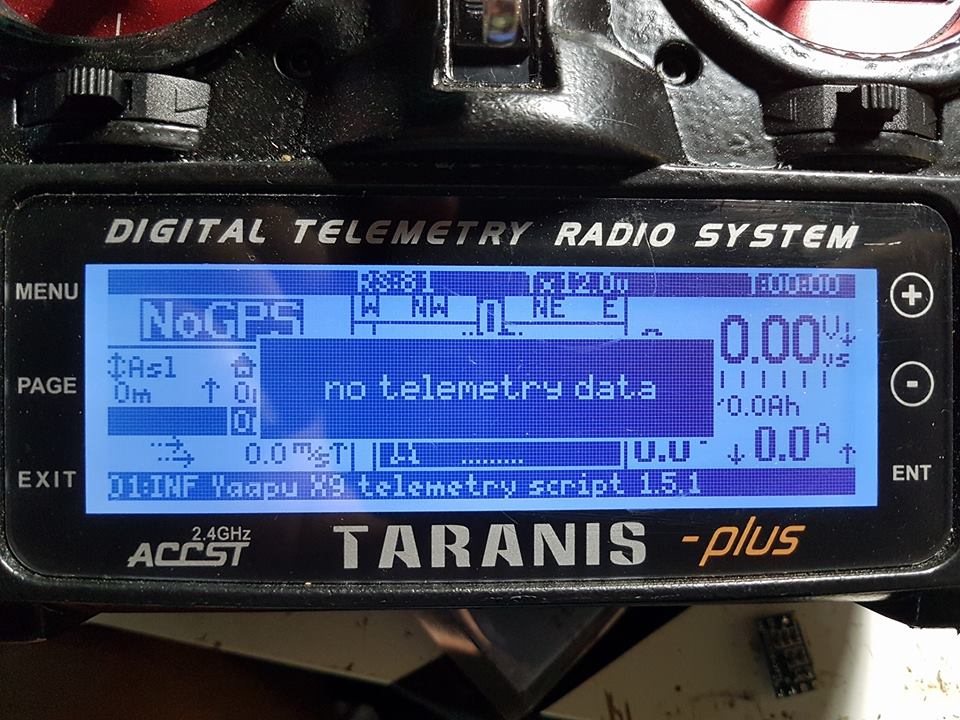
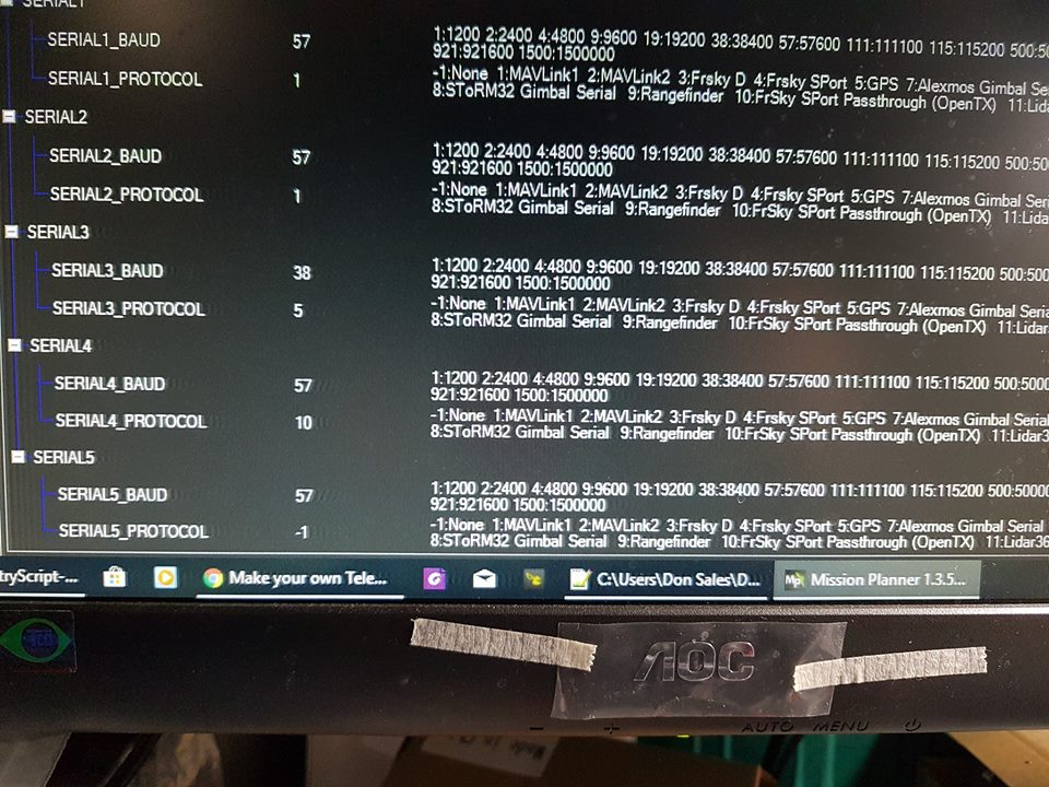
Now setup your serial port to output either FrSky Sport telemetry, or to use the excellent scripts by Alex choose the XPort option, and have fun.

11 Likes

Great thanks, should be a wiki page as well for posterity :slight_smile:

thanks @LuisVale very informative

I just want to add that on cheap clones I had heating issues when powered at 5.2v and had to insert a series resistor on Vcc to lower the tension to 3v or less, I’m using 22 Ohms and the IC is just warm to the touch.
This is probably only due to the very cheap max3232 ICs I use so YMMV

Super guide, defiantly should be on the WIKI

Have just finished mine, used a spare diode on the Vcc to drop the voltage down to 4.2 ish, could use two but i think 3.2v might be a bit too low.

3 Likes

Hello all!
I followed all the steps. But, I only have 4 sensors so far. Maybe someone can chime in an share how they set up theirs.

Hi,
a quick check, first clear all sensors and run discovery again while the yaapu script is not running.
You should discover GPS, if you do not discover the GPS sensor than the problem is in the cabling.

Once you get the cabling working you can run discovery again this time with the yaapu script running and you should discover all other sensors exposed to OpenTX by the script.
(This second step is not mandatory)

Alex

Thanks Alex.
Still the same.
I will try to make another one this weekend. But what puzzles me because it is able to receive the Vertical Speed but that’s only it.

You get vspd because I expose it to OpenTX even if I do not get telemetry from the RX, it’s a minor issue that I have to fix.

To test connectivity you have to unset the yaapu script from the telemetry page and only then do the remove and discovery to check for GPS which is the only discoverable sensor sent by ardupilot

1 Like

Hello alex, here are some of the sensors that my Horus recognizes, but the script still does not work, am I doing something wrong?

. I could not upload the second image, so I’ve put a link to my NAS http://gofile.me/6wrvR/wwqK0khE0

The script only supports ardupilot frsky passthrough protocol.
You select it in mission planner as serial protocol 10.

With this protocol you will discover only GPS.

What is your current setup?
Which version of ardupilot are you running and how did you setup telemetry?
Which cable are you using with which autopilot?

Hi Alex,

Great script !! I have installed it in my Horus X10S. My setup is a hexacopter with pixhawk 2,1(ardupilot version 3.5). I am confused about the telemetry cable. I will try the above setup for the cable and try. One more question. When I turn off the transmitter and turn it on back again the script stops running and I get back the old openTX screen, is there any way to start the script automatically when the transmitter is turned on?
Thanks

Hi @Pavan,
the current Horus version is not a widget and cannot be started at radio power on.
Widgets have many limts, lower priority for instance and cannot accept user input from the radio buttons, that’s the reason why I choose to write a script to run as “one time” and as such cannot be started automatically.

For specific questions about the script you can also use the other thread, this one is more “cabling” oriented :slight_smile:

cheers,
Alex

Thanks for this mod Luis. Very usefull and working !

Tried making one of these cables as well. Connected Telemetry2 on the Cube to S.Port, set SERIAL2_PROTOCOL to 10 in Mission Planner, yet discovery on the X7 (with or without yaapu running) gives no sensors. The board doesn’t heat up though, so I may have messed up the soldering.

the most common error I’ve seen is with mixing RX and TX lines.

Not sure of the pinout of the Cube, but just wired another one to plug on the PixHack v5 serial 2 port and worked the 2nd time (Yeah, I mixed RX and TX :smile: :blush:) and connected to a X4R receiver

I believe that I made a confusing comment regarding the cabling. I have the Horus script now running on my Horus and the cable I made is connected to the cube. It is the same as Luis is showing at the beginning. No swapping of Rx and Tx.
Sorry for that.

I’ve spent hours and hours trying to get this working, building cables from the FUL-1 and from this guide, to no avail. Honestly I wish I’d bought the Craft and Theory solution from the beginning, it would have saved me a lot of time and money…

:joy:

C’mon @fnoop I can do one of these in less than 5 minutes (and this includes warm up time of the soldering iron and crimping pins for the plugs), and 10 minutes if you mix the rx/tx lines :slight_smile: so it’s more or less the same time as pressing the buy it now button on a web browser :rofl:

Also, test this with everything on (Radio and rc receiver), because the telemetry protocol is only active when the receiver demands for it, and this is the same either for store bought or diy adapters…

I sat down during the footie last night and I just about had it finished at the end of penalties - you may be able to do it in 5 mins but the vast majority of people who want to fly a drone can’t. I’m not a soldering newbie but I hate cables and components, life’s just too short. Anyway I’ve got it made now, thanks for your instructions. The components are tiny and you end up with a neat cable.
It’s still not working, but who knows what that’s about…

Got it finaly working with 2 diodes on Onmibus with X4R sb. With the first board and 1 diode the board got very hot. Even after putting the second diode. So I was happy I ordered 4 of them :wink:
Thanks for lay-out and ‘wiki’ :+1:

Well… that also didn’t work out. After the 4th boot it also burned out… and the 3th one also on my pixhawk with x8r…