Wim, would be good to see some photos of your implementation to try and figure why you are having these issues. Cheers
Hi Paul,
looks like some batches of those MAX3232 boards do have issues, I have 10 of them that would work, get very hot and eventually burn.
I have found references https://electronics.stackexchange.com/questions/122769/max3232-overheating-burnt-after-connecting-to-pc of similar problems and all ultimately point to defective chips, I guess it’s just a matter of luck 
I just got a batch of 10 and sent one to Wim. I need to test these I guess! Thanks for the heads up Alex.
I found out the same. If I connect the PC to the FC the 3232 get,s very hot. No PC connection via USB no problems, all is working and stays cool.
These are really a lottery to get good chips. I’m sorry for all the hassle
I also think its a lotery😜
I can try to make a photo, but the only one I have left is the one from Paul  the rest is gone…
The only setup that is working good is with the 2 transistors and 3 resistors. Than I have a super transmitter Thanks to Yaapu 
you’re very welcome
Hi All
I’am going to make cable to connect kakute f7 aio v2 and frsky r-xsr.
I have a few questions:
R-XSR have only one pin for smart port ( no separate GND and VCC pin) So it should be only one wire between max3232 and r-xsr ?
On kakute I have 3.3v output (200 mA max) is it enought ?
Do I have to solder any resistor , diode or capacitor ?
Thx in adavnce
Regards
Tomek
Sorry, but have no experience with that setup, both the kakute or the r-xsr, so can’t be of assistance.
An update on my personal “lottery” with the max3232 ICs, I bought 10 genuine TI MAX3232ECDR SOIC-16-N chips and swapped the defective ones I originally had on the boards and now everything works as expected.
The new ICs are cool to the touch even at 5.5V…
The genuine parts are around 2$ each so overall still a very cheap and (now) reliable solution
3 Likes
Hi,
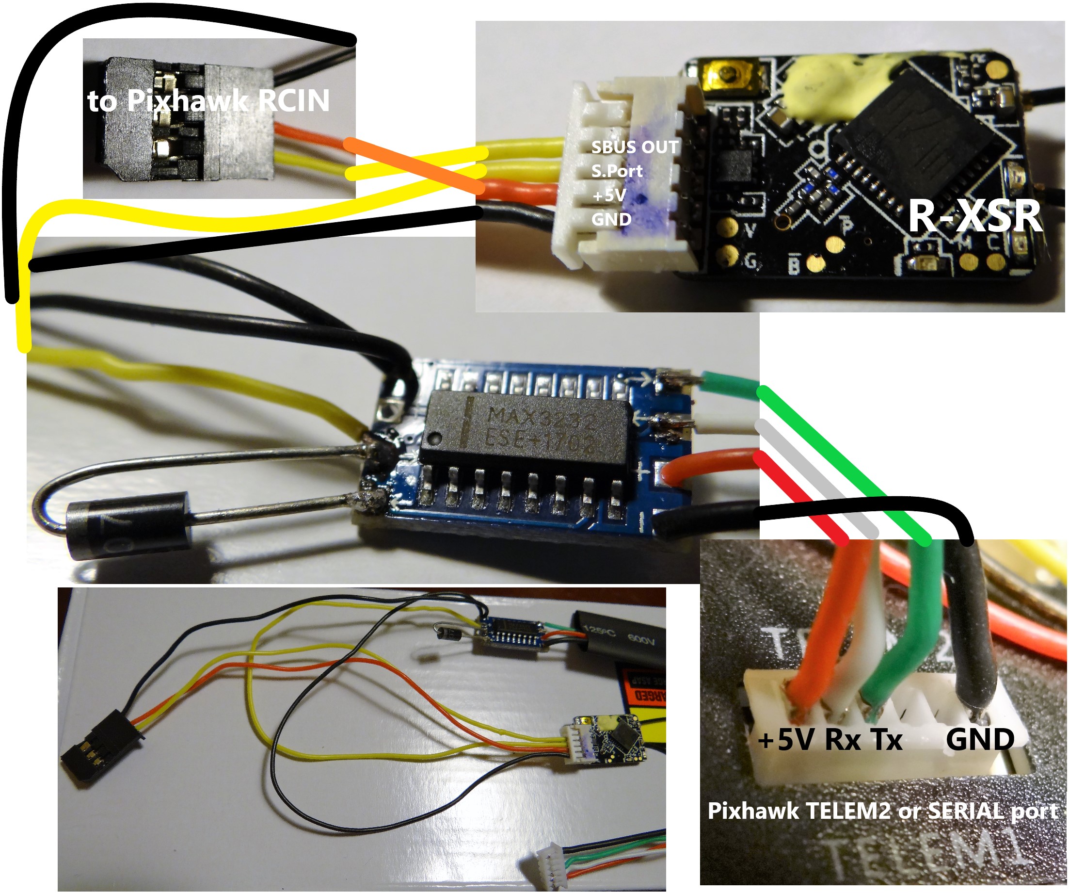
I have successfully managed to connect R-XSR to Pixhawk with Frsky telemetry passthrough. Yaapu script is working perfectly, MAX3232 does not overheat, may have been lucky with my batch.
R-XSR has only one connector port, so you have to share GND with RCIN and telemetry.
I hope this scheme may be helpful:
1 Like
Great!!
Thanks for adding another receiver to the list.
I guess we better start to think about adding a wiki entry…
1 Like
Works also with Frsky R-X4R, but was not lucky with MAX3232 chip, had to replace it with an original TI chip. Works perfect with Alex script.

1 Like
What flight controller is that? Pixracer?
The PixRacer does not need the external inverter. You can simply use the FrSky telemetry port
http://ardupilot.org/copter/docs/common-pixracer-overview.html#frsky-telemetry-serial4
And the board on the image is not a PixRacer
1 Like
F4 OMNIBUS V3 AIO flight controller
1 Like
Sorry guys, I’ve been trying to do this for hours now but I still can’t discover GPS on my QX7. One clarifying question: When the pinouts say “TX”, do they mean “This is TX”, or “Connect TX here”, ie “This is RX”? I’ve tried both to no avail, I have my own custom-designed level-shifter and inverter board that works fine for other uses, but I’ve been having no luck getting telemetry from my XSR.
To be clear, I connect the third pin from my XSR (Vcc, GND, SPort) to the inverter, then the output of that to the third pin (or second?) from the left of my Serial4/5 on my PixHawk and set SERIAL4_PROTOCOL to SPort Passthrough, correct?
Hi Stavros,
this is not a one way protocol, you need both rx and tx from the PixHawk, that’s the reason for the diode on the rx side.
The rx polls the s.port bus by writing to it and the FC needs to “read” data from uart rx pin to detect the polling.
The FC responds by “writing” data to the uart TX pin.
s.port is half duplex two way and inverted.
Ah, thank you, @yaapu. Which pin is the RX pin, in this case? My XSR only has SBUS, SPort and CPPM.
1 Like
Oh you mean on the same pin, and the diode is to prevent backflow? I see now, that should be an easy fix, thank you.
EDIT: Would it be possible for someone to provide a simple inverter schematic? The post confuses me a bit because mine is custom-designed and it’s different from what is posted.