Introduction
Continue from part 1 and as part of the ongoing labs, this time we will:
- Have some discussion on how the system works, what and why some extra steps are required.
- Finish installing all necessary packages to use the Intel Realsense T265 with ArduPilot in ROS.
- Verify that everything is working in ground test, then comes actual flight test.
This blog is divided into the following sections:
- Prerequisite
- System overview
- ArduPilot parameters
- ROS packages installation
- Workflow process
- Ground test and flight test
- Conclusions and next steps
Let’s get started.
1. Prerequisite
Suppose you have followed the steps outlined in the 1st blog, your vehicle should have:
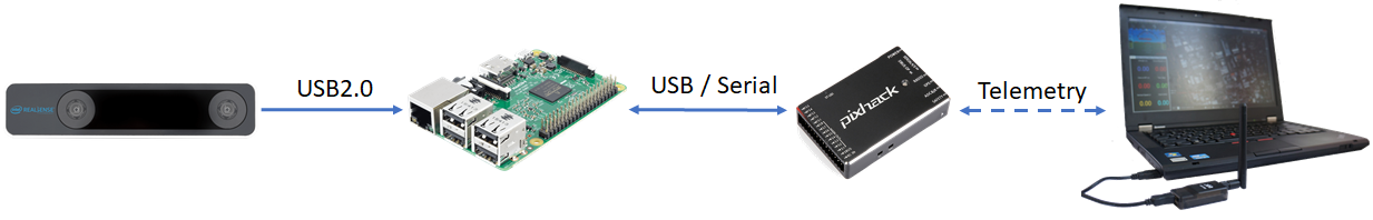
- An onboard computer capable of polling pose data from the T265, i.e. USB2 port (Raspberry Pi 3 Model B with 16GB micro SD card in my case).
- Working installation of librealsense and realsense-ros.
The steps below should work out-of-the box with a T265 camera facing forward. Other camera orientations can be used with appropriate modification of launch parameters. See section 4 for more details.
2. System overview
In this section, I will attempt to explain the overall system and the parts that are most subject to change, from a technical standpoint. This is not by any means an exhaustive explanation of how everything works, so if you are keen to learn more, additional references can be found at the end of this blog.
Let’s break the system down into more manageable units, from hardware to software:
- Physical connection:
- Data flow: The green boxes are ROS nodes.
Using mavros, there are a number of topics that can be used to transfer external navigation data to ArduPilot, with the following have been proven to work with experiments:
| Name | Main difference |
|---|---|
| VISION_POSITION_ESTIMATE | Accept euler angles (roll, pitch, yaw) |
| ATT_POS_MOCAP | Accept quaternions |
We will convert the position data contained within /tf and send to mavros via the topic /mavros/vision_pose/pose. Mavros will take care of the ENU - NED frames transformation and send it to ArduPilot through MAVLink.
Our approach is made possible only thanks to the awesome contributions by the members of the community. Just to name a few:
– Experiment with Visual Odometry - ROVIO part 1 and part 2 by @ppoirier
– Indoor flight with external navigation data by @chobitsfan
– Successfully using motion capture system as indoor GPS by @chobitsfan
– Indoor autonomous flight with Arducopter, ROS and Aruco Boards Detection by @anbello
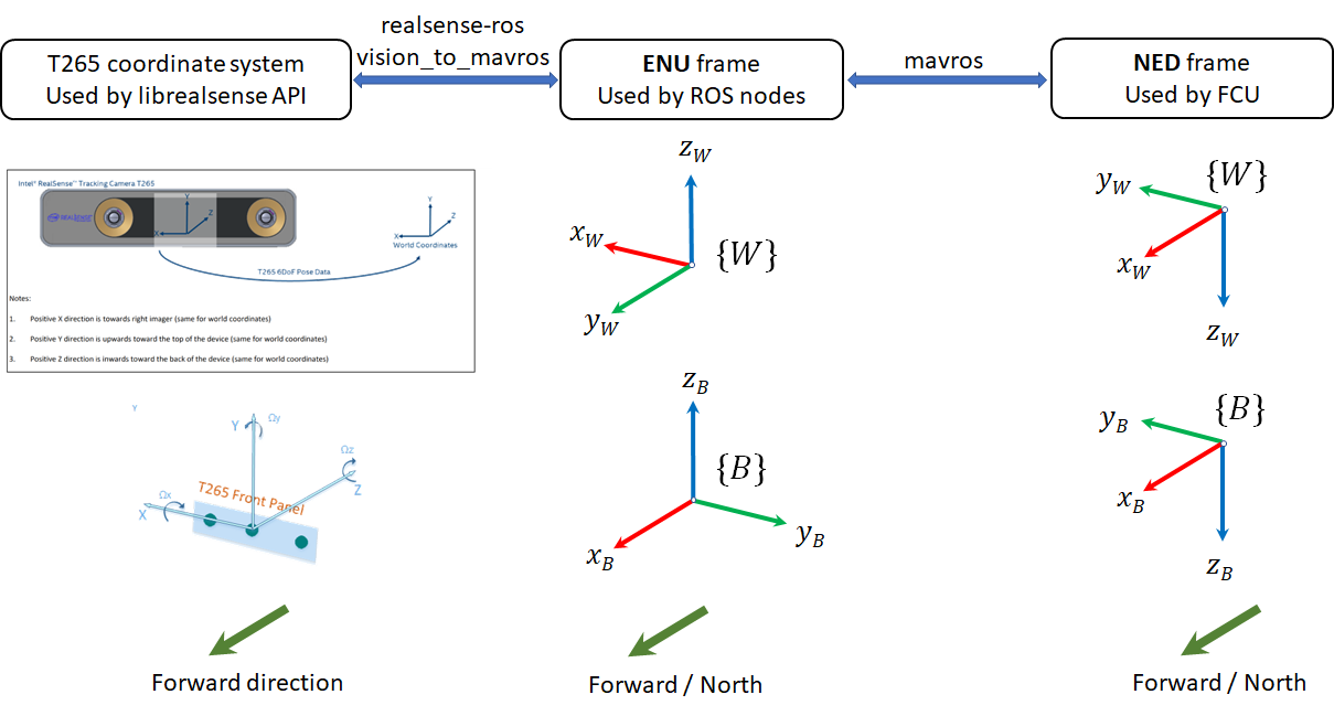
- Reference frames: The body {B} and world {W} frames used by
librealsense, ROS and ArduPilot are all different.realsense-rosprovides position feedback in ENU frame, however different camera orientations and frame alignments need to be taken into account before sending pose data to mavros, which are done byvision_to_mavros. More on this in the next part.
From left to right: T265 frame, ENU frame (ROS side), NED frame (FCU side). Whatever orientation of the T265 is, we need the feedback to be in ENU before sending to mavros.
vision_to_mavrospackage: this package has 3 main functions:- Convert ROS topics between
realsense-rosandmavros: /tf is the the transformation data which lets the user keep track of multiple coordinate frames over time. Many localization packages provide this type of data out-of-the-box./tfwill be converted to/mavros/vision_position/pose, which is now supported by ArduPilot. - Limit rate of pose data: 200Hz data stream seems to fast for the FCU to handle. We also don’t need the full stack of 200Hz of data. 10-15Hz localization data is the bare minimum threshold that is required for testing, and 30Hz should be more than enough for most cases (relative to how fast the vehicle is moving). You can change the rate data with
output_rateparam. - Frames alignment: The position feedback from
realsense-rosis already in ROS convention (ENU). However, by default the T265 body’s X-axis will be aligned with world’s X-axis initially, which means the FCU will interpret heading as facing “East”, or yaw will be off by 90 degrees (left image, below). This package will rotate the body frame by 90 degree around world’s Z-axis, which would conform to ROS’ ENU convention (right image, below).
- Convert ROS topics between
Note 1: there are hidden APIs that can make things much easier
According to this thread: there is a way to handle frames alignment withinlibrealsensethat allows users to define the forward direction in T265’s body coordinate system and then define which direction in the world coordinates it could be lined up with initially. However, this functionality is not yet exposed for outside use except by Intel. Once that becomes available, things can be much more simplified.
Note 2: you can do everything within
realsense-rosif you want
You can also do everything (publish correct topics, align frames) by modifying the data and topic withinrealsense-ros, specificly by changing this file: realsense-ros/realsense2_camera/src/base_realsense_node.cpp at 2b3365f5c96fcafa53412881e8e4484a6648bc23 · IntelRealSense/realsense-ros · GitHub
Note 3: you can do everything without ROS if you want
The green boxes in the data flowchart are ROS nodes. If you want to do away with ROS, make your own application that can grasp pose data from librealsense’s API and send to ArduPilot, using your favorite language / framework (here’s the full supported list).
That’s all for the explanation. Let’s make it happen.
3. ArduPilot parameters
- FW version: tested with ArduCopter-stable 3.6.9. Latest stable version can be download from Mission Planner or here.
Note on FMU version (extracted from this comment by @rmackay9): The fmuv3 firmware is the one to use for the Pixhawk1 and Pixhawk2/Cube boards. The only real difference between the “fmuv2” and “fmuv3” is that “fmuv2” has a few less features so that it can fit onto the older Pixhawks with the 1MB limit. The ChibiOS builds are all below 1MB so even the fully features firmware fits on the older Pixhawks now.
-
Which EKF is supported? I have tested with EKF2. The following params are for EKF2. As of this writing, EKF3 is not handling external navigation data until this PR is merged.
-
Params:
# For EKF2

AHRS_EKF_TYPE = 2

EK2_ENABLE = 1

EK3_ENABLE = 0

EK2_GPS_TYPE = 3

EK2_POSNE_M_NSE = 0.1

EK2_VELD_M_NSE = 0.1

EK2_VELNE_M_NSE = 0.1

# Similar for both EKFs

BRD_RTC_TYPES = 2

GPS_TYPE = 0

COMPASS_USE = 0

COMPASS_USE2 = 0

COMPASS_USE3 = 0

SERIAL5_BAUD = 921 (the serial port used to connect to Raspberry Pi)

SERIAL5_PROTOCOL = 1

SYSID_MYGCS = 1 (to accept control from mavros)
Note for developers (many thanks to @anbello for pointing these out):
- VISION_POSITION_ESTIMATE message, consumed in GCS_Common.cpp, don’t use VISO_* params.
- VISO params, consumed in AP_VisualOdom.cpp, are only relative to VISION_POSITION_DELTA message.
- EK2_EXTNAV_DELAY parameter can now be used on 3.7-dev.
4. ROS packages installation
Installation:
- Establish serial connection: Connect RPi to ArduPilot with MAVLink
- If the connection between RPi - ArduPilot is established via the UART serial port: change the setting in /boot/config.txt
- Install MAVROS
- Establish connection in ROS: Connect to ArduPilot with MAVROS.
- Synchronize clock/time.
- Install vision_to_mavros package
# Navigate to catkin workspace

cd ~/catkin_ws/src

# Clone and build the repo

git clone https://github.com/hoangthien94/vision_to_mavros.git

cd ..

catkin_make

# Add source command to .bashrc, if you have not done so

# echo "source ~/catkin_ws/devel/setup.bash" >> ~/.bashrc

source ~/.bashrc
-
Modify parameters of
vision_to_mavrosfor your T265’s orientation:
The default parameters are set for a front-facing camera. Simply modify the launch file t265_tf_to_mavros.launch: change the paramsroll_cam,pitch_cam,yaw_cam,gamma_worldwith values corresponding to your setup:- T265 facing front or down
- T265’s USB port pointing to which side of the vehicle
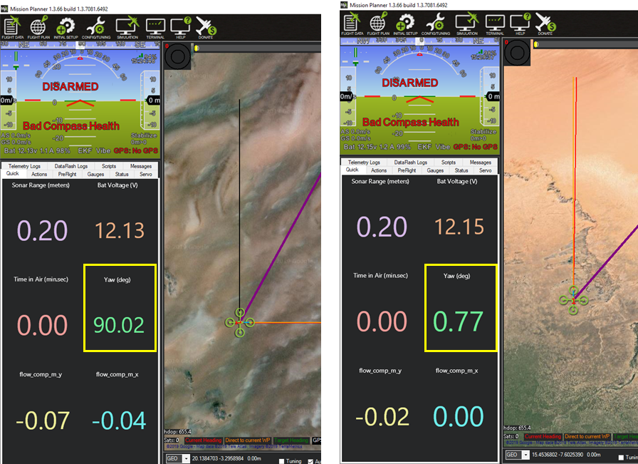
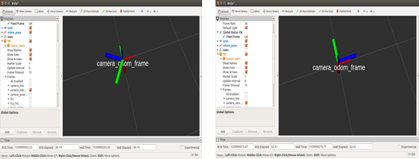
Important note for down-facing configurations: there is an ongoing issue about inconsistent yaw angle when T265 is facing down and some workarounds have been discussed. As of this writing, here is what seems to work: the camera needs to be slightly tilted (i.e. not completely flat out) when it starts streaming poses (launching
realsense-rosor calling librealsense’ API to invoke pose data), otherwise the yaw angle of the world coordinates might be randomly initialized, as shown below:
Left: T265 facing down, completely flat at launch - inconsistent yaw angle between runs
Right: T265 facing down, slightly tilted at launch - consistent yaw angle.
Verify that each ROS node is working:
There are 3 nodes running in this setup. Launch in 3 separated terminals on RPi:
- T265 node:
roslaunch realsense2_camera rs_t265.launch- The topic
/camera/odom/sample/and/tfshould be published at 200Hz.
- The topic
- MAVROS node:
roslaunch mavros apm.launch(withfcu_urland other parameters inapm.launchmodified accordingly).rostopic echo /mavros/stateshould show that FCU is connected.rostopic echo /mavros/vision_pose/poseis not published
- vision_to_mavros node:
roslaunch vision_to_mavros t265_tf_to_mavros.launchrostopic echo /mavros/vision_pose/poseshould now show pose data from the T265.rostopic hz /mavros/vision_pose/poseshould show that the topic is being published at 30Hz.
Verify that ArduPilot is receiving data from MAVROS
Check that ArduPilot is receiving position data by viewing the topic VISION_POSITION_ESTIMATE on GCS. For Mission Planner, press Ctrl+F and click on “Mavlink Inspector”, you should be able to see data coming in.
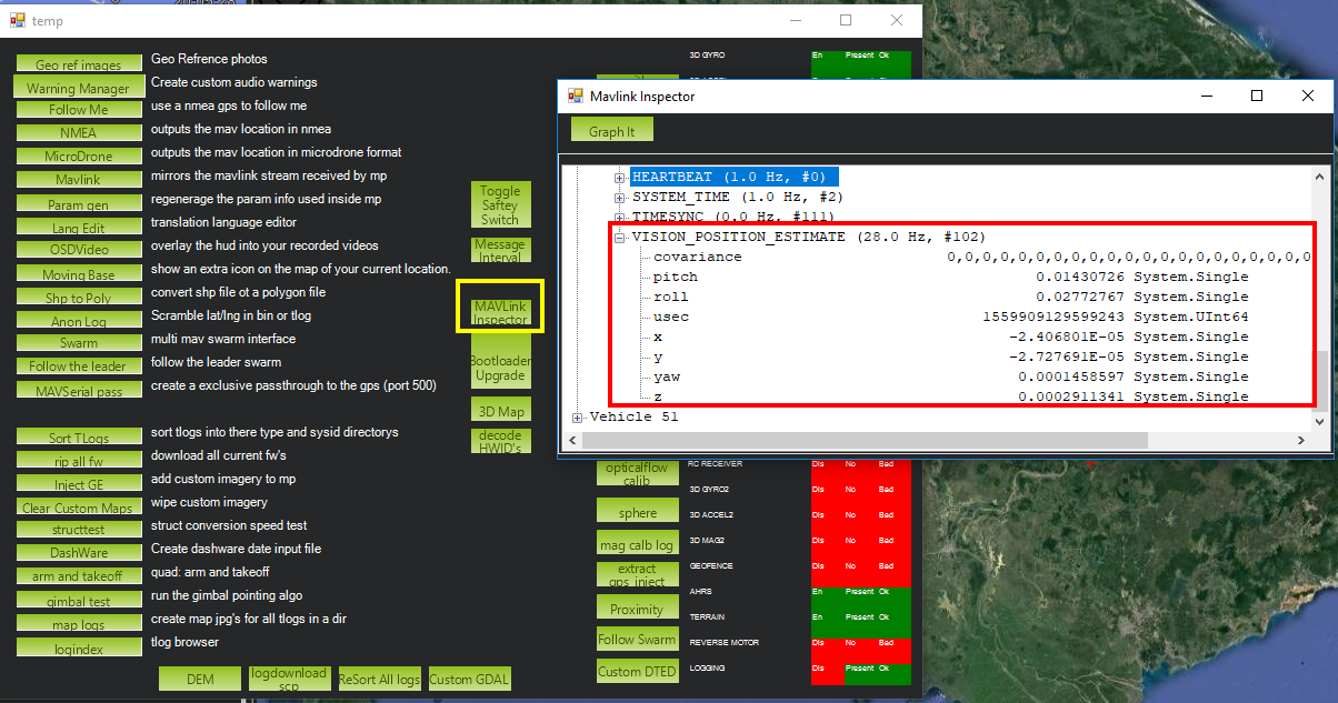
Note on viewing
VISION_POSITION_ESTIMATEtopic on QGC: check this thread if you have some problems with receiving this topic on QGC.
Launching all nodes at once
Once all nodes can run successfully, next time you can launch all of them at once with roslaunch vision_to_mavros t265_all_nodes.launch, which will launch:
rs_t265.launchas originally provided byrealsense-ros, no modification.apm.launchmodified with your own configuration.t265_tf_to_mavros.launchwith parameters according to your T265’s orientation.
5. Workflow process
With all the ROS packages working and ArduPilot parameters configured, we can finally start testing and flying. However, quite a number of steps need to be carried out in specific order, enough so that I think a dedicated section is required to clarify all the details involved.
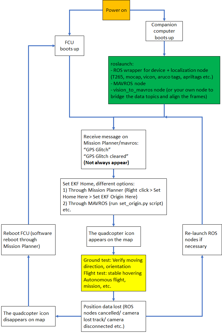
To better understand the workflow, below is a diagram showing how a successful run might look like. This workflow can also apply to other external navigation systems (mocap, vicon, aruco tags, april tags etc.), with the main difference being the green box. Specifically, for different systems you need to change:
- ROS wrapper for sensors/devices.
- Localization package.
- Data bridge and frame alignment between the localization package and MAVROS.
For the Realsense T265, the ROS driver is realsense-ros, the localization package is running onboard the device itself, vision_to_mavros will bridge the topics between realsense-ros and mavros, lower the data frequency and align the frame.
Note: this workflow is gathered from my reading on the forum and verified by experiments. Obviously, I might be wrong / missing some important details. Any feedback would be greatly appreciated!
Let’s start at the beginning, after you connect the battery:
-
After power on (red block), you can launch the ROS nodes (camera node, mavros node, vision_to_mavros node).
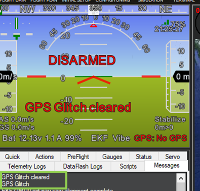
-
Generally (but not always), once MAVROS is running and the FCU starts receiving
VISION_POSITION_ESTIMATEmessage, you will see the “GPS Glitch” and “GPS Glitch cleared” message confirming that the external localization data is being recognized by the system.
-
Now, you need to tell the EKF where the vehicle is in the world (i.e. set EKF home), otherwise incoming data will not be fused. To do this, you need to send SET_GPS_GLOBAL_ORIGIN and SET_HOME_POSITION MAVLink messages. There are a number of options for this to be done:
- On Mission Planner (easiest option): Right-click on any point on the map > Set Home Here > Set EKF Origin Here.
- On the companion computer: use any methods to send the required messages to the FCU through MAVLink. Follow this blog by @anbello, I have copied the script set_origin.py in the
vision_to_mavrospackage.
- On Mission Planner (easiest option): Right-click on any point on the map > Set Home Here > Set EKF Origin Here.
-
You should see the quadcopter icon appear on the map.
-
Now you need to zoom in to the maximum in order to see any movements.
-
At this point, you can carry on with ground test, flight test, autonomous test, etc.
-
Along the way, for whatever reason if
VISION_POSITION_ESTIMATEdata is lost, the quadcopter icon will disappear. As far as I know, you cannot re-set EKF home, thus the only option is to reboot the FCU, either through Mission Planner (Ctrl-F > Reboot Pixhawk) or power cycle the system.


The next section will discuss the actual operation (ground test, flight test etc.) of the vehicle, i.e. the yellow block in the flowchart.
6. Ground test and flight test
Follow the last section until you see the quadcopter icon appears on the map, zoom in to maximum.
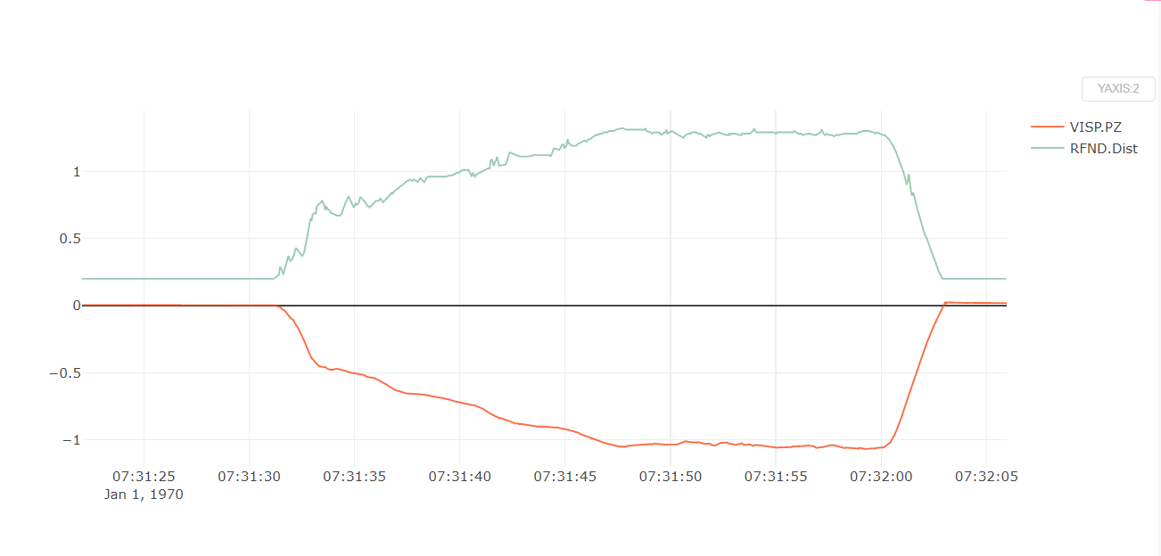
Ground test:
- Hold the vehicle up, move around and observe the trajectory of the vehicle on Mission Planner.
- Do a back and forth, left and right, square or any pattern you like. The trajectory of the vehicle on the should reflect accordingly without too much distortion or overshoot.
First flight test:
For the first few flight tests, I think it’s best to do an overall check:
- Confirm that position feedback is running ok before switching to Loiter mode.
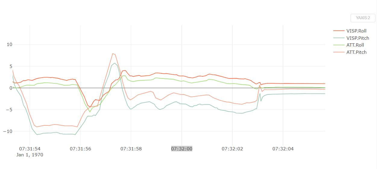
- Verify tracking performance (scale, oscillation etc.).
- Look out for the working boundary in your environment, i.e. where tracking might be lost due to lack of features, fast or rotation movement.
Here is what I would suggest:
- Takeoff in Stabilize or Alt-Hold, check that the vehicle is stable.
- Move the vehicle around and observe the position on Mission Planner as well as rviz to see if tracking is stable.
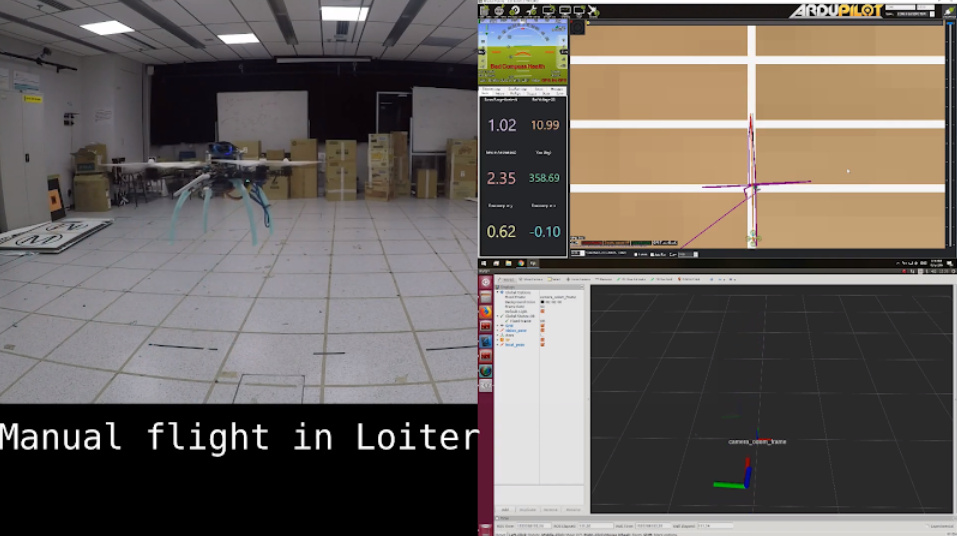
- Switch to Loiter, but always ready to switch back to Stabilize/Alt-Hold if anything goes awry.
- Otherwise, the vehicle should hover stably and able to keep its position.
- Move the vehicle back and forth 2-3 meters, verify the scale (easier to view on rviz).
- Move the vehicle around (translate, rotate) at varying speed, always ready to switch back to Stabilize/Alt-Hold.
Flight tests:
Once you feel confident, you can take off directly in Loiter.

7. Conclusion and next steps
In this blog we have taken a closer look at our overall system, install necessary packages, configure ArduPilot and ROS params to use ArduPilot with the Intel Realsense T265 tracking camera. Ground test and flight test can be carried out after user has gotten familiar with the working procedure.
Next time, in lab 4, we will explore some simple autonomous experiments. Since we are using ROS, numerous examples are available, but we will start with these scripts, many thanks to @anbello for this awesome work. Then in lab 5 we will discard the ROS framework and use python wrapper instead to capture data from the T265 and communicate with ArduPilot directly. You can refer to my first blog for an updated list of all the labs once they are out.
Hope this helps. Happy flying!
References
ROS frame convention: REP 105 -- Coordinate Frames for Mobile Platforms (ROS.org)
ENU-NED coordinate: External Position Estimation (Vision/Motion based) · PX4 Developer Guide
Some Informative papers: