Introduction
In this part of the ongoing labs, we will demonstrate how to make a MAVLink bridge between the Intel Realsense T265 and ArduPilot in Python, without the use of ROS. The choice of Python is strictly optional, and you can use any other wrappers supported by librealsense.
Although this blog (non ROS-based) shares the same structure as part 2 (ROS-based), the content of the two are vastly different:
- Prerequisite
- System overview
- ArduPilot parameters
- Python packages installation
- Workflow process
- Ground test and flight test
- Conclusions and next steps
1. Prerequisite
Please refer to part 1 for a detailed discussion on hardware requirements, then follow the installation process until librealsense. Since we are not using ROS, realsense-ros is not required for this blog.
In a nutshell, what we need on our vehicle is:
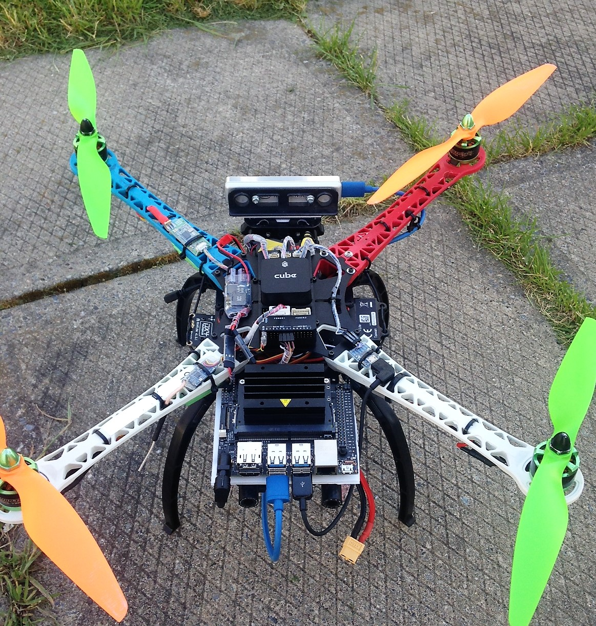
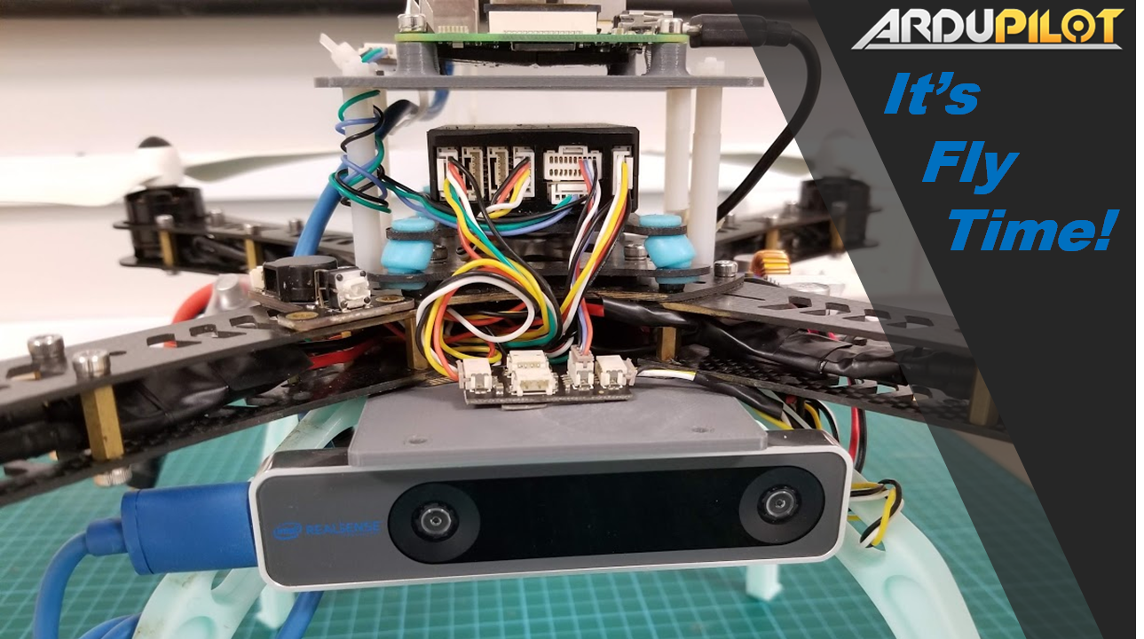
- An onboard computer capable of polling pose data from the T265, i.e. USB2 port. In this case, we will be using a Raspberry Pi 3 Model B for this experiment.
- A working installation of librealsense.
- A facing forward Realsense T265 camera. Different camera orientations can also be used with correct modification of transformation matrix. We shall take a closer look in the next section.
2. System overview
From a physical standpoint, here’s how we connect everything:
- Physical connection:
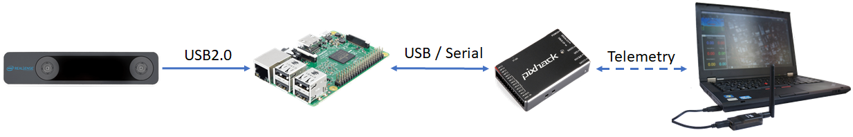
The physical connection diagram and testing procedure are about all that are similar between this blog and part 2 (ROS based). From this point onward we are dipping into uncharted waters.
- Data flow:

| Name | Details |
|---|---|
T265: Pose data |
Running at 200Hz, each sample contains: - 6-DOF pose data: Position vector [xyz] + Orientation quaternion [xyzw] - Confidence level: [high / medium / low / failed] - Linear velocity and acceleration vectors - Angular velocity and acceleration vectors |
T265: Pose data → Confidence level |
Confidence level (or pose data confidence, tracking confidence) has the value of {0x0 - Failed, 0x1 - Low, 0x2 - Medium, 0x3 - High}.The value corresponds to the local tracking quality of the device and for most applications you should trust the full 6dof pose only in high confidence. If you only need the rotation (3dof), lower confidence poses can be used (source). The confidence level depends on various parameters such as lighting of the scene, number of features, etc. It’s advised that the T265 gains a high confidence in order to obtain a high quality of tracking (source). |
FCU: VISION_POSITION_ESTIMATE |
Accept Euler angles (roll, pitch, yaw). Used to transfer external navigation data to ArduPilot. |
FCU: VISION_POSITION_DELTA |
Has a field named confidence - normalised confidence value from 0 to 100 (%). Used as a dummy message to send confidence level to GCS. |
We are interested in using 6-DOF pose data (position + orientation) for localization and viewing confidence level obtained from the T265 camera. For that to happen, we need a script that does the following:
-
6-DOF pose data: after getting a new data from the T265, we perform frame transformation to align the internal frame of T265 with NED convention, then send the pose to ArduPilot through the MAVLink message
VISION_POSITION_ESTIMATE. Since the FCU might get “frozen” with too much incoming data (remember that the pose data is coming at 200Hz), the message needs to be sent at a predetermined frequency that the FCU is capable of handling but also not too slow (relative to the speed of the vehicle), i.e. 10-30Hz. -
Confidence level: Embedded within the data coming from the T265. I believe it would be of immense benefit to users if the level of tracking confidence can be viewed directly from the GCS. For lack of a dedicated message, we will utilize a message that is not being used by the FCU which contains a field that is as similar to what we are sending as possible.
VISION_POSITION_DELTAwith its fieldconfidenceseems like a good candidate for the job. Since we do not need to update the confidence as often as pose data, it should be updated as a slower frequency, i.e. 1Hz.
Note 1: Relative to
VISION_POSITION_DELTAmessage areVISO_params, consumed in AP_VisualOdom.cpp.
Note 2:confidence levelis not yet supported inrealsense-rosuntil this PR is merged.
I hope everything is clear up till now, because here comes the confusing parts.
- Frame coordinates: First up, the documentation of T265 on master branch of
librealsenseis behind the one on development branch, so you should look for information mainly on the development branch.
Within the T265 device itself there are multiple frames coordinates for different sensors. Specifically, we have: pose stream, gyro and accelerometer (IMU), fisheye cameras (source). As can be seen in this picture:

Note:
realsense-viewerseems to display data in each sensor’s own coordinate and the documentation does not reflect that so well for now.
What we are looking for is the frame coordinate of pose data. Taken from the wiki (dev branch):
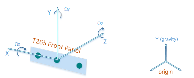
To aid AR/VR integration, the T265 tracking device uses the defacto VR framework standard coordinate system instead of the SDK standard:

1. Positive X direction is towards right imager
2. Positive Y direction is upwards toward the top of the device
3. Positive Z direction is inwards toward the back of the device

The center of tracking corresponds to the center location between the right and left monochrome imagers on the PCB.

When T265 tracking starts, an origin coordinate system is created and RealSense SDK provides T265 poses relative to it. Origin's Y axis is always aligned with gravity and points to the sky. Origin's X and Z axes are not globally set, but determined when tracking starts depending on the initial orientation of the T265 device. The origin coordinate system is always right-handed.
And from this thread:
[The origin coordinate system] is deterministic, though, so if you start tracking with T265 at the same position and orientation, your origin will be defined the same always. In the specific case in which you start tracking with the fisheye sensor looking forward, origin will be defined the same as the T265 pose stream (X pointing right, Y up, Z backward).
In summary:
- There are multiple frame coordinates on the T265. Suffice to say, not everything is well documented.
- The T265’s pose data is measured in an
originframe. - The
originframe always has Y-axis upwards, but X and Z depend on the camera’s initial position + orientation, which should produce the sameoriginframe every time the system runs.
Note: for downfacing configuration, there seems to be a problem with inconsistent yaw angle between runs. The temporary fix is to tilt the camera a little (not facing flat down) when the system starts.
- Frame transformation: Suppose that we have the T265 fixed on the frame in some orientation, whether forward facing or downfacing, and we can verify that the
originframe is the same every run. To send the pose data to FCU through MAVLink, the data needs to follow NED convention through the following transformations:

What we have is (2), which is the data coming from T265. In order to obtain (4), which is the pose that can be sent to FCU, we need to define (1) and (3), then multiply them in the right order: (4) = (1).(2).(3). For the case of forward facing camera, as depicted in the picture, (1) and (3) are simply the reverse of one another.
For a more in-depth explanation, you can go through the following references:
-
Euler angle rotation: Understanding Euler angles
-
In the picture,
(1),(2),(3),(4)are homogeneous transformation matrices: http://planning.cs.uiuc.edu/node111.html, each consists of a rotation and displacement (translation) part. For(1)and(3), the displacement components are zeros. -
Putting it all together: This script
t265_to_mavlink.py, which is a part of thevision_to_mavrospackage, will do the following tasks:- Capture 6-DoF pose and confidence level data from
librealsense. - Convert pose data from T265 coordinate system into NED coordinate system.
- Encode the aligned pose data into
VISION_POSITION_ESTIMATEmessage and send it to the FCU as a determined frequency. - Map the value of confidence level data from T265 from
[0,1,2,3]to[0,33.3,66.6,100] - Encode the remapped confidence data into
VISION_POSITION_DELTAmessage and send it to FCU as a determined frequency. - Automatically set EKF home: the script will listen to the message
GPS GlitchandGPS Glitch Clearfrom ArduPilot, which is an indicator that the EKF is receiving external navigation data and EKF origin can now be set, then send commands to set EKF home and origin. This will be further explained in the next section.
- Capture 6-DoF pose and confidence level data from

Explanation completed. Let’s go flying.
3. ArduPilot parameters
-
FW version: tested with ArduCopter 3.7-dev. Latest stable version can be download from Mission Planner or here.
-
Which EKF is supported? As of this writing, only EKF2 will accept external navigation data.
-
Params:
AHRS_EKF_TYPE = 2
EK2_ENABLE = 1
EK3_ENABLE = 0
EK2_GPS_TYPE = 3
EK2_POSNE_M_NSE = 0.1
EK2_VELD_M_NSE = 0.1
EK2_VELNE_M_NSE = 0.1
BRD_RTC_TYPES = 2
GPS_TYPE = 0
COMPASS_USE = 0
COMPASS_USE2 = 0
COMPASS_USE3 = 0
SERIAL5_BAUD = 921              (the serial port used to connect to companion computer)
SERIAL5_PROTOCOL = 1
SYSID_MYGCS = 1                 (to accept control from mavros)
4. Python packages installation
Installation:
- Establish serial connection: Connect RPi to ArduPilot with MAVLink
- If the connection between RPi - ArduPilot is established via the UART serial port: change the setting in /boot/config.txt
- Install python3: Python 3 Installation & Setup Guide – Real Python
- The basic examples provided by Intel can be found in the folder
~/librealsense/wrappers/python/examplecan be run with python3.
- The basic examples provided by Intel can be found in the folder
- Install pip for Python3 (
pip3): https://linuxize.com/post/how-to-install-pip-on-ubuntu-18.04/#installing-pip-for-python-3 - Install Python packages:
# pip install may require sudo, proceed accordingly
pip install pyrealsense2
pip3 install transformations
pip3 install dronekit
pip3 install apscheduler
# Install serial packages if necessary
sudo pip3 install pyserial
- Download the script
t265_to_mavlink.py. In case you have downloaded the vision_to_mavros package, the scripts can be found in the folderscripts.
# Navigate to the location of the scripts
cd ~/path/to/the/script/

# Download the scripts if you haven’t already:
wget https://raw.githubusercontent.com/hoangthien94/vision_to_mavros/master/scripts/t265_test_streams.py
wget https://raw.githubusercontent.com/hoangthien94/vision_to_mavros/master/scripts/t265_to_mavlink.py

chmod +x t265_test_streams.py
chmod +x t265_to_mavlink.py
- Update the
PYTHONPATHenvironment variable to add the path to thepyrealsenselibrary. Alternatively, copy the build output (librealsense2.soandpyrealsense2.soin~/librealsense/build/) next to the script.
export PYTHONPATH=$PYTHONPATH:/usr/local/lib
- Run a test script to verify python3,
librealsense,pyrealsenseand connection with the T265.
# Run the test script
python3 t265_test_streams.py
# You should see a short stream of pose data coming from the T265 on the terminal
- Modify transformation matrices: The script works out of the box for forward facing camera, for other configurations, change the following two transformations matrices, corresponding to
(1)and(3)above:H_T265body_aeroBodyandH_aeroRef_T265Ref. - Modify parameters of
t265_to_mavlink.pyfor your system configuration, which can also be passed as input arguments from the command line, specifically:
#######################################

# Parameters

#######################################

# Default configurations for connection to the FCU

connection_string_default = '/dev/ttyUSB0'

connection_baudrate_default = 921600

# Default frequency for pose and confidence messages

vision_msg_hz_default = 30

confidence_msg_hz_default = 1
- Run the main script:
# For serial connection: set udev.rules in order to get the USB available; allow permission to serial
sudo chmod 666 /dev/ttyUSB0

# When everything is working and all defaults are set:

python3 t265_to_malink.py

# View input arguments:

python3 t265_to_mavlink.py --help

# Run the script with input arguments, example:
python3 t265_to_mavlink.py --connect /dev/ttyACM0 --baudrate 57600 --vision_msg_hz 20--confidence_msg_hz 0.5
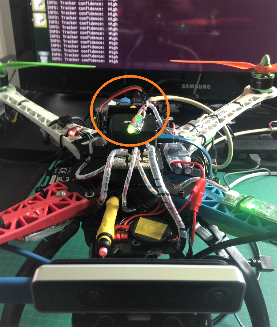
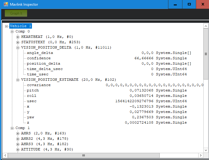
Verify that ArduPilot is receiving pose data
Check that ArduPilot is receiving position data by viewing the topic VISION_POSITION_ESTIMATE on GCS. For Mission Planner, press Ctrl+F and click on “MAVLink Inspector”, you should be able to see data coming in under Vehicle 1.

Note on viewing
VISION_POSITION_ESTIMATEtopic on QGC: check this thread if you have some problems with receiving this topic on QGC.
Verify that ArduPilot is receiving confidence level data
View the topic VISION_POSITION_DELTA on GCS, field confidence should show the remapped value of confidence level.
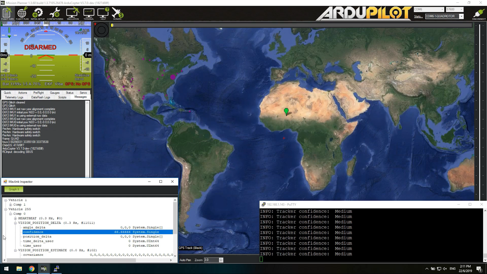
Voice and message notification on Mission Planner for tracking confidence level
Changes in tracking confidence level can also be notified on Mission Planner’s message panel, HUD and by speech. These notifications will pop up when the system starts and when confidence level changes to a new state, for example from Medium to High.
- To enable speech in Mission Planner: Tab Config/Tuning > Planner > Speech > tick enable speech.
- If there are some messages constantly displayed on the HUD, you might not be able to see / hear the confidence level notification.
- If telemetry is slow, notification might be dropped. You can still see the latest message in MAVLink Inspector, message
STATUSTEXT.
5. Workflow process
The tasks that are needed to be done are the same as part 2. However, this time around the process is simplified by letting things run automatically using code.
Short description:
- After boot, log in to the companion computer, navigate to the script and run it:
python3 t265_to_mavlink.py - Wait until the quadcopter icon appears on the map of Mission Planner.
- All done. Now you can carry on with the flying.
- If the external navigation data is lost for any reason (tracking lost; script is interrupted etc.), reboot the FCU/system and go back to step 2/1.

Long description:
Let’s start at the top:
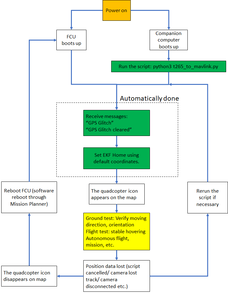
-
After power on (red block), you can run the script:
python3 t265_to_mavlink.py, assuming all the default values are correct. -
Once the FCU starts receiving
VISION_POSITION_ESTIMATEmessage, you will see the “GPS Glitch” and “GPS Glitch cleared” message confirming that the external localization data is being recognized by the system. -
Incoming data will not be fused unless the EKF knows where it is in the world (home). The script will attempt to send SET_GPS_GLOBAL_ORIGIN and SET_HOME_POSITION MAVLink messages. You should see the quadcopter icon appear on the map. The location of home is defined here and you can change to anywhere, as long as the values are non-zero. If the quadcopter icon does not appear, you can also set EKF home directly from Mission Planner and soft-reboot the FCU.
-
You now need to zoom in to the maximum in order to see the actual movement.
-
At this point, you can carry on with ground test, flight test, autonomous test, etc.
-
Along the way, for whatever reason if
VISION_POSITION_ESTIMATEdata is lost, the quadcopter icon will disappear. As far as I know, it seems that you cannot re-set EKF home, thus the only option is to reboot the FCU, either through Mission Planner (Ctrl-F > Reboot Pixhawk) or power cycle the system.

Now we can move on to the actual experiments.
6. Ground test and flight test
Ground test:
- Hold the vehicle up, move around and observe the trajectory of the vehicle on Mission Planner.
- Do a back and forth, left and right, square or any pattern you like. The trajectory of the vehicle on the should reflect accordingly without too much distortion or overshoot.
- If you are flying in a confined environment, it might be best to go around the safety perimeter of flying, view the trajectory on the map, then remember not to fly/perform mission beyond that perimeter.
- View the confidence level and verify tracking performance. As suggested here, for most applications you should trust the full 6dof pose only in high confidence. If you only need the rotation (3dof), lower confidence poses can be used.

Flight tests:
- Confirm that position feedback is running ok before switching to Loiter mode.
- Verify tracking performance (confidence, scale, oscillation etc.).
- Look out for the safety boundary in your environment.
Note that in the video, the scene has very few features (mostly black background and glass), but the tracking and localization quality is still quite accurate for most of my experiments.
[Optional] Get the script self-start as part of a service
If you are going to do a lot of testing (especially for beta testers), we can go one step further and let the script start automatically at boot time. Huge thanks to @ppoirier for your suggestion.
- Make sure you are using the latest version of
t265_to_mavlink.py, which includes the following changes:
– Added this to the beginning to make the script self-executable:#!/usr/bin/env python3
– Added env variable so it can findpyrealsense2:
# Set the path for IDLE
import sys
sys.path.append("/usr/local/lib/")
- Download the following shell or create a shell file
t265.sh:
cd /path/to/scripts/
wget https://raw.githubusercontent.com/hoangthien94/vision_to_mavros/master/scripts/t265.sh
- Modify the path to
t265_to_mavlink.pyin the shell filet265.sh, then make it executable:
nano /path/to/t265.sh

# In t265.sh, change the path to t265_to_mavlink.py, in my case:
# /home/ubuntu/catkin_ws/src/vision_to_mavros/scripts/t265_to_mavlink.py

chmod +x /path/to/t265.sh
- Test that the shell can run:
./path/to/t265.sh
# the script t265_to_mavlink.py should run as normal
- In the steps below, we will use
systemdto turn it into a service. Depends on your system, use any other methods that work for your case. - Let’s create a file called
/etc/systemd/system/t265.service:
[Unit]
Description=Realsense T265 Service
After==multi-user.target
StartLimitIntervalSec=0
Conflicts=

[Service]
User=ubuntu
EnvironmentFile=
ExecStartPre=
ExecStart=/home/ubuntu/catkin_ws/src/vision_to_mavros/scripts/t265.sh

Restart=on-failure
RestartSec=1

[Install]
WantedBy=multi-user.target
-
Make the following changes to
t265.serviceabove:
– Set your actual username afterUser=
– Set the proper path to yourt265.shinExecStart= -
That’s it. We can now start the service:
systemctl start t265
-
Run
topto see if the service is running. Use Mission Planner to verify data (VISION_POSITION_ESTIMATEandVISION_POSITION_DELTAmessages) is coming through. -
Finally, automatically get it to start on boot:
systemctl enable t265
7. Conclusion and next steps
In this blog, we have discussed the underlying principles of how to incorporate a VIO tracking camera with ArduPilot using Python and without ROS. After installing necessary packages, configuring FCU params, ArduPilot can now integrate the tracking data and perform precise navigation in GPS-less environment. Pose confidence level is also available for viewing directly on GCS to quickly analyse the performance of the tracking camera. Thanks to the new simplified operating procedure, experiments can now be carried out as a much faster rate.
With this, we have completed the sequence of weekly labs for my ArduPilot GSoC 2019 project. From this point onwards, more work will be done on the code implementation side. As such, schedule for the next lab will depend on different factors (devs & PR approval). However, I believe the completed labs will be a strong foundation for any folks who are interested in beta testing.
Hope this helps. Happy flying!