Thanks to the excellent work from @olliw42 and experiments from @mike, I finally decided to start experimenting with UAVCAN, following this blog.
I present here a simple project, that may interest some of you that are looking to add more serial interfaces and cannot switch to an alternative technology like I2C or SPI.
It is using off the shelf modules that you can order from the usual web suppliers for a few bucks and by interfacing 2 x Benewake TFMINI serial RangeFinder, you can make a basic avoidance with a range of 12 Meter Indoor and 6 Meter Outdoor.
Building the DIY Nodes
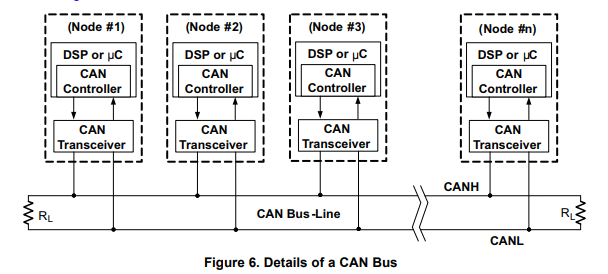
Looking at the schematic above, you need:
2 STM32F103C8 development board, also called "BluePill’
2 SN65HVD230 Can transceiver module, CJMCU-230
1 SILAB CP 2102 (CJMCU–CP2102) or a FTDI USB -TTL Adapter
You can build using different techniques, ProtoBoard, BreadBoard or "DeadBug’’.
Take note that some of the modules may be defective or marginals, I suggest you order some spares just in case.
We are building 2 Modules:
UC4H SLCAN Adapter
The SLCAN adapter is an indispensable tool for checking and debugging the proper functioning of a UAVCAN network. In simple terms, it is a USB-CAN adapter, which is connected to the CAN bus on the one side and via USB to a PC on the other side. On the PC side the UAVCAN GUI Tool, which is freely available as part of the UAVCAN project, provides a nice software for doing a lot of things, such as spying the messages on the CAN bus, plotting data, setting node parameters, and so on .
UC4H UartBridge Node
The UC4H UartBridge node allows one to connect any device with a standard UART/serial port, such as a GPS module, and to communicate with it through the CAN/UAVCAN bus. It’s like a USB-TTL adapter, except that the USB frontend is now UAVCAN. The UC4H UartBridge node provides two UART ports (this limit is imposed by the hardware of the used STM32F103T8/C8/CB chips).
TOOLS Required:
-
STM Flash Loader software to upload the binary files on the bluepill
Here is an excellent blog on how to flash , including the link to get the tools
This is your first exercice, you need to master it as you will use it a lot !
https://circuitdigest.com/microcontroller-projects/programming-stm32f103c8-board-using-usb-port -
UAVCAN GUI Tool https://uavcan.org/GUI_Tool/Overview/
-
Download and extract the Binary files (in .bin & hex formats) https://github.com/olliw42/uavcan4hobbyists
-
BetaCopter
http://www.olliw.eu/storm32bgc-wiki/STorM32-ArduPilot
Some modifications to the ArduCopter firmware were made and the result called BetaCopter, which provides simply the best support of STorM32 gimbals.
Upload BetaCopter on your Flight Controler :
Select the ‘u’ variant from the binary files and update the firmware of your flight controler using Mission Planner (Load custom file)
STEP 1
Build the UC4H SLCAN Adapter and flash it with the latest release
/uavcan4hobbyists/firmware/binaries/uc4h-slcan-v009.hex (or bin)
!!Note, you need to specify the extension when using the STM flashing tool in order to see the files!!
If you are using the CP2102, you need to patch the driver in order to get the correct speed, look here:http://www.olliw.eu/storm32bgc-wiki/How_to_configure_CP2102_USB_adapters_for_high_baud_rates
Next you can connect to the flight controller - PixHawk in this project- and enable the CAN as showned in @mike blog: Configuring Ardupilot for UAVCAN
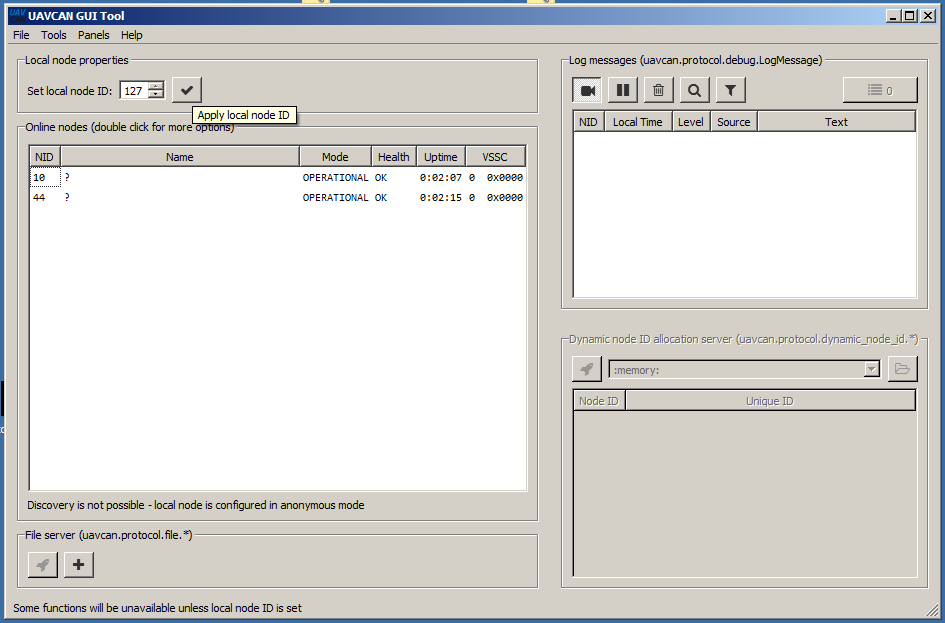
Then you can connect the SLSCAN tt Flight Controler as showned in the schematic above and launch the UAVCAN GUI Tool , select the port and set speed at 1000000. You should see the initial GUI interface, click on “local nide ID” and you can click on Dynamic Node if you dont see the node 10 , that is default for PixHawk. More on @mike second blog: UAVCAN: CANbus for the rest of us
STEP 2
Build the UC4H UartBridge Node and flash it with the latest release
/uavcan4hobbyists/firmware/binaries/uc4h-uartbridge/uc4h-uartbridge-v007.hex (or bin)
!!!ABOUT THE BENEWAKE TFMINI DATA FORMAT !!!
At the time of this lab I experienced some instability while using the TFMINI in native mode (Binary Output). Using the clear text mode -pix format- , the Node is working flawlessly. There are numerous reference showing how to flash the rangefinder in this mode, just make sure you send this sequence for pix format output 42 57 02 00 00 00 04 06 and that you can read distances as clear text on a terminal @115200baud.
STEP 3
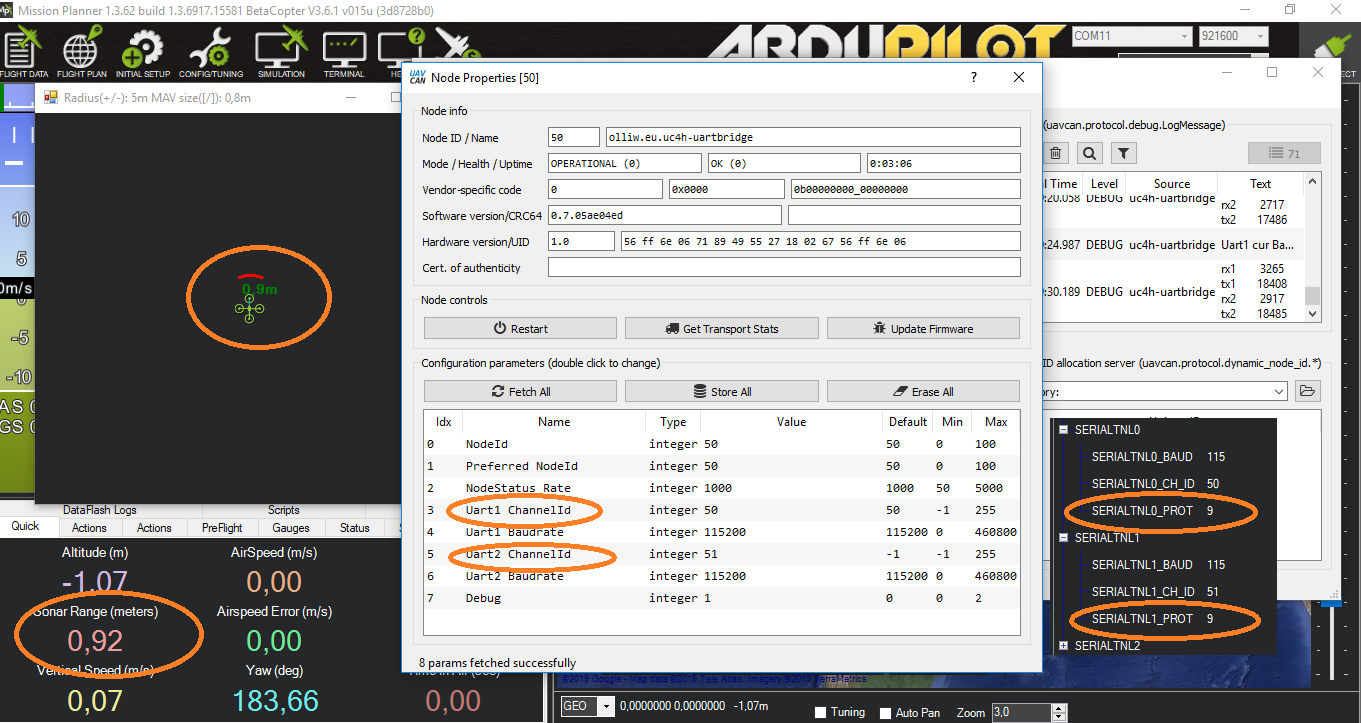
Once complete you should be able to start node and connect with the SLSCAN in order to set the parameters of node (See picture center below ). Then you start Mission Planner and set 2 of the the 3 Serial Tunnels SERIALTNL according to the Speed , The Channel ID and the signal type = 9 being Range Finder. Finally you set the RangeFinder configuration for the 2 instances using Orient 25 -Looking Down - and type 8 (Lightware serial as we send clear text values from TFMINI as explained above) for the first and Orient 0 -Looking Forward - and type 8 for the second.
You should get readings as “Sonar Range” for the Looking Down and on Mission Planner you hit CTRL-F and select proximity (bottom right) to get the “Radar Screen” for the “Looking Forward” rangefinder.
That’s it, we added 2 serial sensor (with third SERIALTNL still available) and you still have ALL the physical UART available !! 
As a final comment , please note that you can now buy prebuilded and tested nodes (and other models) at low cost from Jdrones Store . Now, any DIY builder can afford to use UAVCAN. This set of boards allows for complete, fully functional UAVCAN drones, with unprecedented features.

 ) you also would have plenty of wiring and electronic boards, yet you would not put in question the concept of it … so it is here, you can do that with just one electronic board, the UC4H general-purpose board