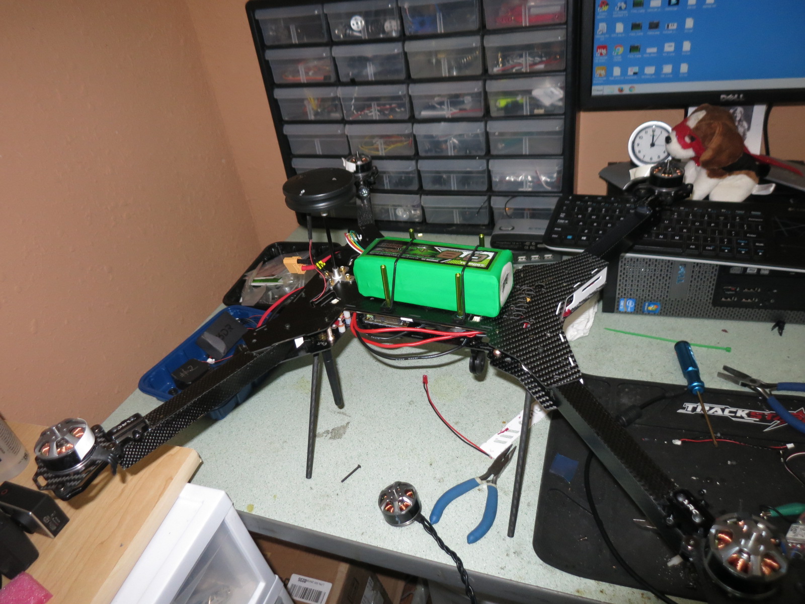
I thought I would add to the UAVCAN article I just posted a note on configuring UAVCAN in Ardupilot. I have built a UAVCAN quad and it is so cool because there are only three connections to the flight controller. Power, CANbus and RCin are all that is required! The UC4H GPS/MAG adapted HERE GNSS, the 4 Zubax ESCs are connected UAVCAN and OlliW’s UAVCAN Powerbrick are all daisy-chained together on the CANbus network.
I used Arducopter 3.6dev because it has revised and more consistent UAVCAN parameters.
First we need to turn UAVCAN on.
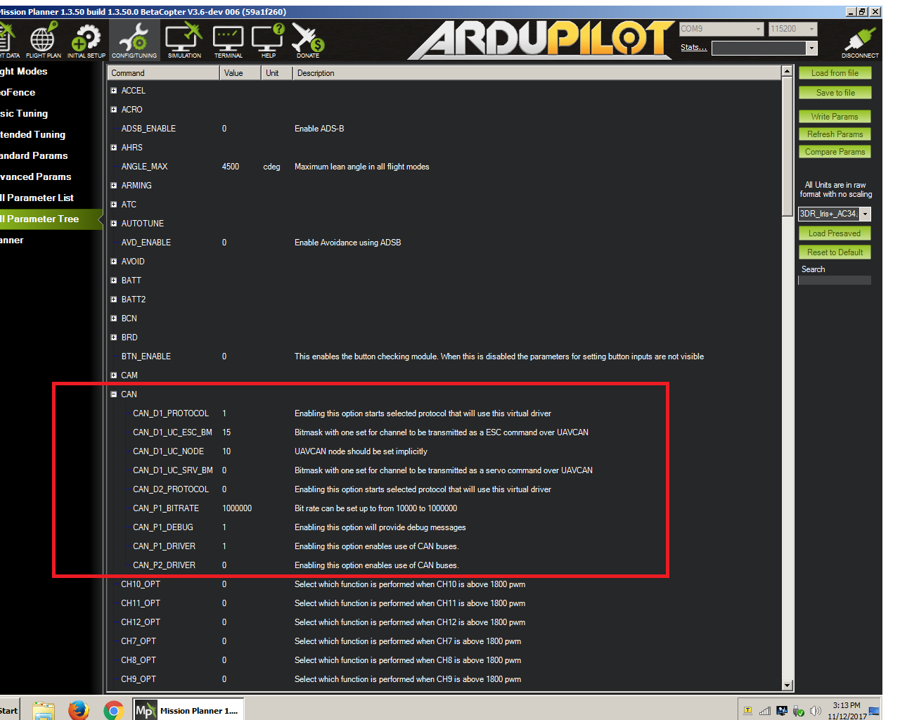
In the advanced parameters you will find the CAN tree. Expand that and you will see:

UAVCAN is capable of fully redundant wiring. A significant step toward greater reliability. You will see two sets of parameters for a CANbus 1 and a CANbus 2. I am using only CANbus 1 for simplicity here. CANbus in the Arudpilot firmware is designed to support multiple CANbus implementations so we first set the protocol to UAVCAN.
Set
CAN_D1_PROTOCOL=1
next we select the driver
CAN_P1_DRIVER=1
edit*
Thanks to EShanaev for clarifying the documentation.
Arducopter is setup to handle multiple CANbus implementations so the CAN_P parameters are designed to control parameters needed for the physical transport aspects of CANbus and the CAN_D are designed to handle the protocol level features. So we see that CAN_P1_driver turns on the CANbus ports. The CAN_P1_BITRATE controls the speed of the CANbus interface. While the CAN_D1_PROTOCOL chooses the CANbus implementation as UAVCAN and CAN_D1_UC parameters control features specific to UAVCAN vs say KDECAN.
Now we have to reboot. The number of CAN parameters visible will increase once CANbus is enabled.
Next we see
CAN_D1_UC_ESC_BM=15
This is a bitmap mask, each position in the binary number represents an ESC to be turned on or off. In my case, of a quad, I have four ESCs, hence 0000 1111 =15. The positions are relative to the ESC index, with the first binary position (the “1” furthest to the right in this binary number 0000 1111) representing esc_index=0. Next position, the second “1” from the right, represents esc_index=1. So for an Arducopter Quad the esc_index=0 is the front right motor and esc_index=1 is the back left motor and so forth.
You enable each ESC individually this way.
CAN_D1_UC_NODE=10
If you remember from the UAVCAN article this is a network of devices called nodes and each node on the bus must have a unique number assigned. The default for the Arducopter flight controller is 10 but that is an arbitrary assignment and you can use any number scheme you like as long as each node has a unique number on the bus.
CAN_D1_UC_SRV_BM=0
LIke the ESC bitmask the servo bitmask enables servos on the bus. I have none so 0 disables all servo messages.
CAN_P1_BITRATE=1000000
The CANbus is a serial bus and this parameter sets the “baud rate” at a million. Fast!
CAN_P1_DEBUG=1 sets the level of debug messages on the bus.
CAN_P1_DRIVER=1 turns on CANbus 1
There is a complete duplicate of these parameters for CAN_D2 if you are using both buses.
Lastly, we set the GPS type parameter to indicate we are using a CANbus GPS.

Pretty slick, eh? Three connections to the flight controller and one cable type and connector for all the other CANbus devices. Try it, you’ll like it. 
Straight off the build, no tuning, stabilize mode:
 Thx.
Thx.