The Shooting Star is a quadcopter drone designed for light shows by Intel.
There have been numerous spectacular demonstrations for swarming models and configurations in the recent years that made the field of experiment out of reach for most of us. Just think of intel record breaking drone shows https://www.intel.com/content/www/us/en/technology-innovation/aerial-technology-light-show.html using hundreds of custom built Shooting Star vehicles and an army of highly specialized operators.
Having worked intensively since the last 2 years with Vision Systems for localisation on GPS denied environment as a Mentor for GSoC, I felt like a little change would be welcome and went back to the root of flying outdoor with RC only and AutoPilot guided planes. This is when I had the idea of adding a ‘‘chase plane’’ that would follow the leader in order to film the plane just like in flight simulator.
In order to do so, I decided to experiments with the basic ‘‘Follow’’ mode that is available on ArduPilot: Follow Mode — Copter documentation
But there is a catch:
When switched into Follow, the vehicle will attempt to follow another vehicle (or anything publishing its position) at a specified offset. The vehicle lead vehicle’s position must be published to the vehicle in Follow mode using a telemetry system.
How to set the Telemetry system in order to retransmit the lead vehicle’s position to many ?
This is where my investigation begin. But before we get into this, just a little bit of theory.
Swarming - Flocking - Shoaling
Flocking is the behavior exhibited when a group of birds, called a flock, are foraging or in flight. There are parallels with the shoaling behavior of fish, the swarming behavior of insects, and herd behavior of land animals. During the winter months, starlings are known for aggregating into huge flocks of hundreds to thousands of individuals, murmurations, which when they take flight altogether, render large displays of intriguing swirling patterns in the skies above observers.
Flocking behavior was simulated on a computer in 1987 by Craig Reynolds with his simulation program, Boids.[2] This program simulates simple agents (boids) that are allowed to move according to a set of basic rules. The result is akin to a flock of birds, a school of fish, or a swarm of insects. Here is a video (with code) showing how to set this behavior:

More experiments with the flocking behavior might be implemented later on. For the moment, as the title says, we will concentrate on simple basic behavior of Follow the Leader for its simplicity and predictive behavior. Additionally, the telemetry configuration is much simpler to implement as there is only one information that is of importance, the Leader Position.
Telemetry options
First, I asked the Grand Master Chef; Andrew Tridgell (aka Tridge) what methods are already available to publish the Leader Position Localisation over radio to many, and here’s the answer:
The key to follow is you want GLOBAL_POSITION_INT to be sent from target vehicle to both GCS and following vehicles . I’ll explain the various methods
1- Use mavproxy to connect to both vehicles, and do this “set fwdpos 1”. That enables forwarding of position msgs (GLOBAL_POSITION_INT) between links
2- Use a multicast link, which gives you a shared transport.
3- Use a mesh radio setup, such as RFD900x with my mesh fw
Based on what is recommended on the ArduPilot WIKI for Telemetry technologies Telemetry (landing page) — Copter documentation I selected the most affordable and easy to implement radios available on this list:
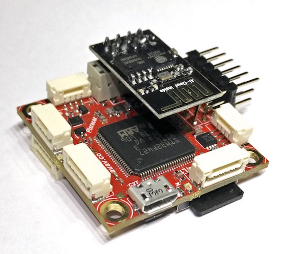
A) ESP8266 (specifically the ESP-01)
These radios are the standard Telemetry unit supplied with the PIXRACER Flight Controler. They are cheap (2$) and easy to configure as they offer a web page for setting the parameters. The range is short, about 100 Meter and can be extended using external antennas on vehicle and high gain antennas on GCS (up to 2 Km).
B) SIK Radio
Classic Telemetry radio that has been proven to be exceptionnaly reliable at moderate distance and quite affordable (15$). Mission Planner offers a simple and efficient method for flashing and configuring the radios. The range is moderate (3-4 km) and this is perfectly suited for this type of experiments.
C) Xbee
Xbee is an excellent technology that has not been very popular on DiY communities because they were expensive and lacked transmission range. They allow different topology like Peer to Peer (PtP) , Multipoint and Mesh. There are now available at a very good price (15$) and offer much more features and longer range than the original version ( 1-2 km).
Additionally, there are complimentary methods of transmission than I am planning to experiment with in the near future: WIFI ( Ad-Hoc and Mesh) and LORA PtP & Mesh as they might be more suited to full swarming capabilities, allowing for peer-to-peer tranmission of Position , Direction, Speed and Velocity.
Configuration and testing with SITL
We have great tools available for configuration and testing and I will explain how to use them in this context. SITL allows you to run ArduPilot on your PC directly, without any special hardware. It takes advantage of the fact that ArduPilot is a portable autopilot that can run on a very wide variety of platforms. Your PC is just another platform that ArduPilot can be built and run on.
https://ardupilot.org/dev/docs/using-sitl-for-ardupilot-testing.html
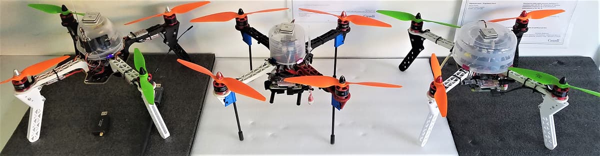
In order to simulate the multi-vehicular configuration, I decided to work with real hardware because utimately , all the vehicles will be fitted with a Companion Computer that will act as a Telemetry Gateway on the first phase and as Behavioral Node on the Swarming phase.
Here is the equipment I will be using
- 2 RaspBerry Pi 3B
- 1 Raspberry Pi 4
- 3 RaspBerry Pi Zero for OnBoard CC
- 4 ESP-01 (with RPI on SITL and with PixRacer on Vehicles)
- 1 UBIQUITY NANO Station + Dlink Router
- 1 WIN10 Laptop for Field testing
- 1 WIN10 Dev PC with Mission Planner and MavProxy + ArduPilot and SITL on WSL2
A note to experimenters:
1- You need to have some experience with Linux and Networking principles in order to make these experiments. I will try to make reference to existing WIKI and ressources on the Blog but it is not intended to be a Linux or Networking tutorial. I am willing to answer questions related to the experiments but not on OS or Networking or FireWall issues (in this case Google , and more specifically :Stack Overflow is your friend).2- There is no security implemented in the links, all is clear and not encoded, even the passwords are defaults to make it easier to document and debug. It’s the experimenter’s responsibility to make sure that this -non existant level of security- is safe enough for real life test.
3- At the time of writing, the default behavior of a vehicle using follow is not safe enough for implementing into UAV (If signal lost, it is just standing there waiting for radio failsafe, or low battery). I am working with a modified version made by Peter Hall that triggers RTL if signal is lost. You can build manually until it is in merged in Master.
Copter: add follow mode RTL timeout · IamPete1/ardupilot@2fe55a2 · GitHub
How to use the RaspBerry Pi with SITL experiments:
Install Raspian and Update
Enable SSH with raspi-config
Rename Local Host to corresponding RPI and SYSID, ex. Pi3-10
Install prereq:
sudo apt-get install libxml2-dev libxslt-dev python-dev
Install MavProxy
sudo pip install mavproxy
Reboot
Download prebuilt bin of ardupilot
https://firmware.ardupilot.org/Copter/beta/SITL_arm_linux_gnueabihf/
mkdir ArduCopter-Prebuild (or any other name)
copy arducopter
chmod +x arducopter
copy copter.parm from ardupilot/Tools/autotest/default_params/copter.parm at master · ArduPilot/ardupilot · GitHub
Initialize
./arducopter --model quad --wipe
Start Mavproxy
mavproxy.py --master tcp:127.0.0.1:5760
Load standard parameters from local directory
param load /home/pi/ArduCopter-Prebuild/copter.parm
Set SYSID and Follow parameters as follow:
Pi4-01 As Leader with SYSID:1
Pi3-10 as follower SYSID:10
Pi3-11 as follower SYSID:11
Set Follow parameters for ID 10 and 11
(refer to Follow Mode — Copter documentation)
FOLL_ALT_TYPE 1.000000
FOLL_DIST_MAX 100.000000
FOLL_ENABLE 1.000000
FOLL_OFS_TYPE 0.000000
FOLL_OFS_X -5.000000 Positionned 5 Meters behind Leader
FOLL_OFS_Y 5.000000 -5.000000 for SYSID:11 (Triangle Formation)
FOLL_OFS_Z 0.000000 Same Altitude
FOLL_POS_P 0.300000
FOLL_SYSID 1.000000
FOLL_YAW_BEHAVE 2.000000
Why and when to use TCP or UDP ?
This question is being asked quite often on forums and discussion groups and the answer is depending on how we interface with the Simulator and GCS. By design, the interface with the Simulator Instances are performed using Serial UART mapping onto TCP ports 5760 to 5763 as described here:
Archived: SITL Serial Mapping — Dev documentation
SERIAL0_ - -uartA= Console tcp:localhost:5760:wait
SERIAL1_ - -uartC= MAVLink tcp:localhost:5762
SERIAL2_ - -uartD= MAVLink tcp:localhost:5763So when we invoke mavproxy.py --master tcp:127.0.0.1:5760 its like connecting to the Console with a serial device. On the other hand, when we want to expand the connectivity to remote systems using MavLink, we can use the --out method as explained here:
Startup Options — MAVProxy documentation
Forward the MAVLink packets to a remote device (serial, USB or network address/port). Useful if using multiple ground station computers or relaying the stream through an intermediate node.
MAVlink usually uses port 14550 for IP-based packet forwarding, though other ports can be used if needed. If forwarding to a network address via tcp or udp, this must be prefixed before the IP address.For experimental transmission like here, it is preferable to use the User Datagram Protocol (UDP) because it is a connectionless protocol that works just like TCP but assumes that error-checking and recovery services are not required. Instead, UDP continuously sends datagrams to the recipient whether they receive them or not. This way, we can have momentary connection interruption and still recover the communication channel, which is not allways the case with TCP.
EXPERIMENTS with MavProxy Forwarding Position message
A) Testing using Ethernet on local network (LAN)
Use mavproxy to connect to both vehicles, and do this “set fwdpos 1”. That enables forwarding of position msgs (GLOBAL_POSITION_INT) between links
With fwdpos enabled, the position signal are passed from one vehicle to the other just if they would be connected together. Allowing the FOLLOW library to process Follower position calculations based on the Leader position (±) the delta position of the FOLL_OFS_X-Y-Z values.
Lab setup
Pi4-01 As Leader with SYSID:1 connected to LAN using Ethernet
Pi3-10 as follower SYSID:10 connected to LAN using Ethernet
Dev PC acting as GCS and MavProxy Position Forwarder (@ 192.168.2.237)
There are numerous methods to start arducopter and mavproxy, the easiest is to start 2 instances of PuTTY for each of the arducopter and mavproxy. I am using Solar-PuTTY from SolarWind that automates most of the session startups. You can also create a service that automatically start at bootup and runs in the background, or any other method you feel comfortable with.
Using Dev PC, SSH using Putty and launch 2 sessions for each Pi:
Pi4-01
./arducopter --model quad
mavproxy.py --master tcp:127.0.0.1:5760 --out udp:192.168.2.237:14560 --out udp:192.168.2.237:14561
Pi3-10
./arducopter --model quad
mavproxy.py --master tcp:127.0.0.1:5760 --out udp:192.168.2.237:14550 --out udp:192.168.2.237:14551
On Dev PC
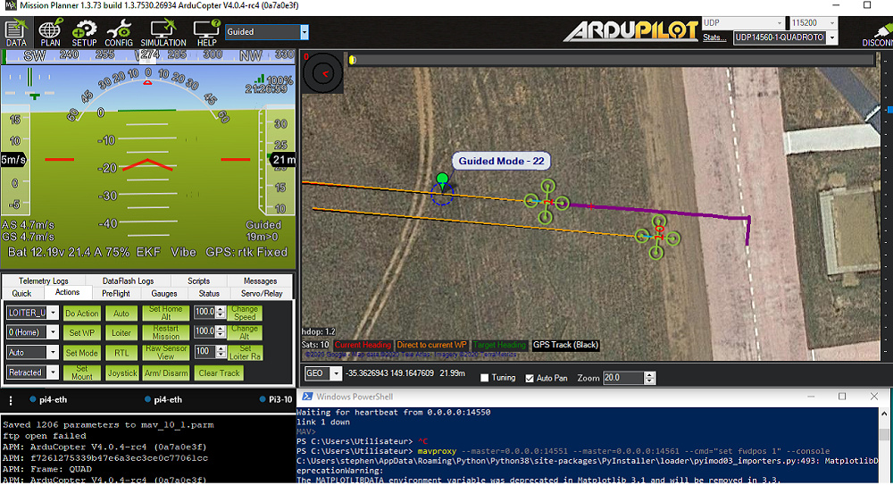
Launch MavProxy with --cmd=“set fwdpos 1” on PowerShell Window:
mavproxy --master=0.0.0.0:14551 --master=0.0.0.0:14561 --cmd=“set fwdpos 1” --console
On Dev PC start Mission Planner
Connect using UDP both Vehicles (Right click over the connection type -UDP- to enable second UDP instance) and switch active vehicle using the scroll down arrow.
Takeoff Leader
Takeoff Follower switch it to FOLLOW mode.
Guide Leader using Map and if everything is correctly configured the Follower should…follow.
B) TESTING with ESP-01 as Stations connected to Acces Point
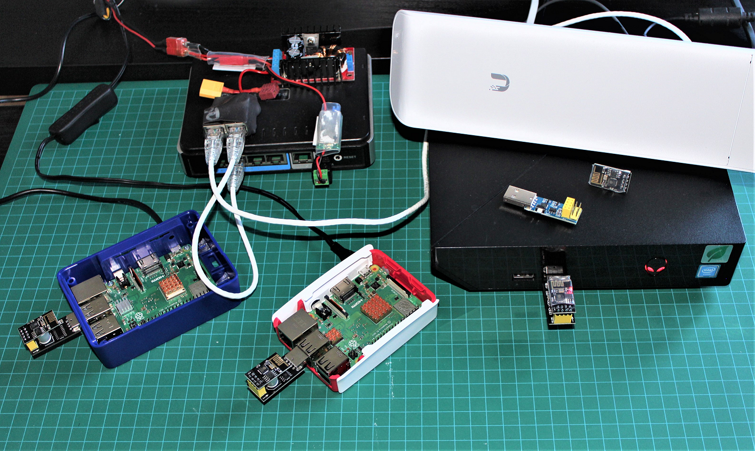
For the first wireless telemetry test we will use the ESP-01, serial to wifi bridge and configure them as Station mode and connect to a Wireless Acces Point. You can use various devices for this ; A High Gain Dongle configured as HotSpot, a Router, as for this project, I had a couple of UBIQUITY NanoStation M2 on hand. This unit has an integrated high gain antenna and a control interface that offers a lot of interesting features like real time signal level and radio throughput graphs. UISP airMAX LiteBeam 5AC XR - Ubiquiti Store
Based on the WIKI, ESP8266 wifi telemetry — Copter documentation
We can flash the ESP with latest code GitHub - tridge/mavesp8266: ESP8266 WiFi Access Point and MAVLink Bridge
Once the components are tested and qualified with SITL , it will be quite easy to install the ESP-01 on PixRacer based QuadCopters and go outside for the real one in the field, using the Nano Station as the GCS Gateway.
Here is a picture of the bench test; on the left , the venerable D-Link router and top right, the UBIQUITY. Take note that these units are powered by 2 set of Step Down regulators and power is supplied in the field by 4S 5000mA Lipo. I find it much easier to work with a USB adaptor designed for the ESP-01. These units are really cheap (1$) and make interfacing and programming so much easier. They come in different shapes with a program switch (BootLoader Mode) and FTDI chips.
Note on reflashing ESP-01
When flashing esp-01 for the second time, the utility does not erase the configuration in EPROM, making it impossible to log on back to AP mode (default). To fix this, wW need to do a Full Erase before reflashing. For this you can use the esptool , a python utility that you can download and use within the PowerShell. Just specify the correct COM port and erase_flash:
esptool.py --port COMx erase_flash
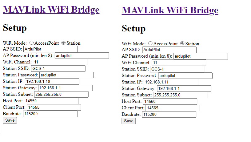
Setting the ESP-01 Mode and configuration:
Connect to the ESP-01 with WIFI by choosing ArduPilot SSID and ardupilot Passwd.
Open a browser to 192.168.4.1 and go to setup to configure into STATION mode, and for each devices, change UDP port configuration according to SYSID and address in the range below
Set the UBIQUITY as a Bridge ( with control interface @ 192.168.1.20)
Configure the SSID as GCS-1 with PassWord: ardupilot
In this configuration it is much easier to use a dedicated router to manage static and dynamic DHCP IP Addressing in the Range of 192.168.1.100 to 192.168.1.111 for GCS and others.
ESP-01 use fixed adressing, we use last digit corresponding to SYSID
SYSID 10 = 192.168.1.10
SYSID 11 = 192.168.1.11
and so on…
Set the Baudrate to 115200 as the USB adapters drivers cannot cope with higher speed.
Save the configuration, double check and reboot the unit.
Once the setup is completed, the web pages @192.168.4.1 should look like these:
2 Vehicles Scenario with MavProxy as GCS
Using Dev PC, SSH using Putty and launch 2 sessions for each Pi:
Pi3-10
./arducopter --model quad
mavproxy.py --master tcp:127.0.0.1:5760 --out /dev/ttyUSB0,115200
Pi3-11
./arducopter --model quad
mavproxy.py --master tcp:127.0.0.1:5760 --out /dev/ttyUSB0,115200
Connect the GCS PC to UBIQUITY and from PowerShell launch:
mavproxy --master=udpin:0.0.0.0:14550 --master=udpin:0.0.0.0:14560 --cmd=“set fwdpos 1” --console --map
Using MavProxy Console select ID 10
From command screen (PowerShell) set ID10 to follow ID 11
param set FOLL_SYSID 11.0
Using MavProxy Console select ID 10 and Arm , Takeoff and put in Follow Mode.
The, select ID 11 and Arm , Takeoff and Navigate using Map, ID10 should Follow.

This concludes the first set of Lab with FOLLOW mode in SITL. Next Blog will cover other methods and technologies of Multi-Vehicles communications like the SIK radios , XBEE and RaspBerry Pi acting as a WIFI Gateway. All these experiments will be eventually tested in real vehicles and I am working on the details of integration and configuration.
Just hope you found this helpfull and triggers some interest to do your own experiments, if that’s the case please update us on your tests.
Other links of this series of blog:
Part 1
Part 2
Part 3
Part 4