
Using Python Script to process MAvlink Position Message
On previous blogs, Mavproxy has been used to transport Leader positionning signal to Followers by enabling the fwdpos option that ‘Forward GLOBAL_POSITION_INT on all links’. What would happen if the Followers would just “capture” this information without the uses of a central process or GCS ?
Using Companion Computer, we can follow the LEADER Position using a program that read Position (and other) messages from the Mavlink feed. This method permits more selectiviy and lay the fondation for OnBoard message processing required for Swarming usage.
Many options are available to process and filter MavLink messages, as is shows on the main page Introduction · MAVLink Developer Guide
We can use different languages and C++ , Python and LUA are commonly used in ArduPilot Community. I prefer working with Python at the moment, but LUA is quite interesting because it allows for scriting directly at the Flight Controller level. I will certainly revisit this option once the MavLink will be implemented on LUA (Work In Progress).
Pymavlink is a low level and general purpose MAVLink message processing library, written in Python. It has been used to implement MAVLink communications many types of MAVLink systems, including a GCS (MAVProxy), Developer APIs (DroneKit) and numerous companion computer MAVLink applications.
With pymavlink, it is possible to create a python script to read sensor data and send commands to an ArduPilot vehicle. This tool is well supported and quite powerfull. You can read more about it here: Pymavlink · GitBook
mav-resender.py
This script is based on Pierre Kancir work on multi-robots systems: Multi systems patrol simulations
This will allow us to revisit the previous test made with MavProxy. In this simple example, based on the WIFI Multicast configuration (mcast:) , we filter the GLOBAL_POSITION_INT message of a specific SYSID (srcSystem = 1 ) and send the result to the locally connected Flight Controler Simulation UARTC (5763):
-Create python script
nano /home/pi/mav-resender.py
from __future__ import print_function
import pymavlink.mavutil as mavutil
import sys

srcSystem = 1
mav_get = mavutil.mavlink_connection(
    'mcast:', source_system=srcSystem)

mav_send = mavutil.mavlink_connection(
     'tcp:127.0.0.1:5763', source_system=srcSystem)

while (True):
    msg = mav_get.recv_match(type='GLOBAL_POSITION_INT', blocking=True)
    if msg.get_srcSystem() == srcSystem:
        print("Message from %d: %s" % (msg.get_srcSystem(), msg))
        mav_send.mav.global_position_int_send(msg.time_boot_ms, msg.lat, msg.lon, msg.alt, msg.relative_alt, msg.vx, msg.vy, msg.vz, msg.hdg)
-Starting
python mav-resender.py
4 A) Testing with WIFI Multicast
Launch 3 x Pi3-10 sessions
./arducopter --model quad
mavproxy.py --master tcp:127.0.0.1:5760 --out udp:192.168.4.8:14550
python mav-resender.py
Launch 3 x Pi3-11 sessions
./arducopter --model quad
mavproxy.py --master tcp:127.0.0.1:5760 --out udp:192.168.4.8:14560
python mav-resender.py
On Pi4-01 Start Arducopter and launch mavproxy:
./arducopter --model quad
mavproxy.py --master tcp:127.0.0.1:5760 --out udp:192.168.4.8:14570 --out mcast:
On Dev PC, connect to RPI4 and start MavProxy at 14570
mavproxy --master=udpin:192.168.4.8:14570 --console --map
SSH into each of the Pi3 MavProxy sessions (using WIFI) and Switch to Guided - Arm - Takeoff - and Follow
On Dev PC: Powershell MavProxy, select SYSID 1 : Guided - Arm - Takeoff

NOTE:
There is a lot of traffic on the WIFI, and the RPI is running 3 shells, making it sometimes a little difficult for the Pi. It is preferable to limit traffic by commenting out the print message once it is proven working OK.
if msg.get_srcSystem() == srcSystem:
# print(“Message from %d: %s” % (msg.get_srcSystem(), msg))
4 B) Testing with XBEE
Pi4-01 as Gateway : 192.168.4.1
Pi3-10 & Pi3-11 connected to Pi4-01 using XBEE reading SCRIPT
Dev PC on WIFI
Change source of signal in mav-resender
mav_get = mavutil.mavlink_connection(
‘/dev/ttyAMA0,57600’, source_system=srcSystem)
We launch the Pi3 just like with Multicast
On Pi4-01 Start Arducopter and launch mavproxy:
./arducopter --model quad
mavproxy.py --master tcp:127.0.0.1:5760 --out /dev/ttyUSB0,57600 --out udp:192.168.4.8:14570
Here we switched to CIRCLE and set speed to 30 Degz/Sec and the link quality is at 100%.
Based on the question on Chapter 2:
Could a different method of handling messages would work better that the mavproxy reflector (set fwdpos 1) would make this technology work better ? We may find the answer in Chapter 4
The scripting method seems well suited for this type of thechnology and it think it is fair to qualify this configuration for live testing.

4 C) Testing with SIK Multicast
This is the configuration of the Pi4 radio that act as endpoint (NodeId:0) of a 3 radio configuration:
[0] S0: FORMAT=27
[0] S1: SERIAL_SPEED=57
[0] S2: AIR_SPEED=64
[0] S3: NETID=25
[0] S4: TXPOWER=20
[0] S5: ECC=0
[0] S6: MAVLINK=1
[0] S7: OPPRESEND=0
[0] S8: MIN_FREQ=915000
[0] S9: MAX_FREQ=928000
[0] S10: NUM_CHANNELS=50
[0] S11: DUTY_CYCLE=100
[0] S12: LBT_RSSI=0
[0] S13: MANCHESTER=0
[0] S14: RTSCTS=0
[0] S15: NODEID=0
[0] S16: NODEDESTINATION=65535
[0] S17: SYNCANY=0
[0] S18: NODECOUNT=3
For Pi3-10 we set nodeid1
[1] S15: NODEID=1
For Pi3-10 we set nodeid2
[2] S15: NODEID=2
We can edit the above with picocom /dev/ttyAMA0 --b 57600 and send “+++” to get in AT mode
Initial testing:
Launching the Pi3 and Pi4 simulation just like with XBEE, the link showed good signal but the Multicast mode was not as stable as expected. It suffered significant lag in the telemetry signal that did not allowed full speed Follow mode ( speed was reduced to 5 Degs./Sec). I have experienced sporadic disconnect-reconnect on the network.
After many tests, I discovered 2 things:
A) The USB based radios are not suited for multipoint communication as the chip/driver combination is subject to lockup and overflow. I switched to direct connection to ttyAMA0 and it made the whole difference !!B) It is much better to connect the radio directly to arducopter with this command:
./arducopter --uartA=uart:/dev/ttyAMA0:57600 --model quad
and just keep MaxProxy for outputting to GCS only.
Here’s the test on Mavproxy:
mavproxy --master=udpin:0.0.0.0:14550 --master=udpin:0.0.0.0:14560 --master=0.0.0.0:14570 --console --map
With this new configuration I was able to get 30 Degs/Sec. no problem with no drop in communication, making this technology QUALIFIED for live test.

Adding STATUS LED
As seen on last Blog, adding a BEACON LED will hep reading health of the Follow system

Using this Python Lybrary, it is easy to control the RaspBerry Pi GPIO:
https://gpiozero.readthedocs.io/en/stable/recipes.html
Here is the code (in bold) that I added to the script so we can control the GPIO connected LED:
from gpiozero import LED
green = LED(21)

    if msg.get_srcSystem() == srcSystem:
        green.on()
#        print("Message from %d: %s" % (msg.get_srcSystem(), msg))
        mav_send.mav.global_position_int_send(msg.time_boot_ms, msg.lat, msg.lon, msg.alt, msg.relative_alt, msg.vx, msg.vy, msg.v$
        #mav_send2.mav.global_position_int_send(msg.time_boot_ms, msg.lat, msg.lon, msg.alt, msg.relative_alt, msg.vx, msg.vy, msg$
        time.sleep(0.1)
        green.off()
Note:
Keep the sleep time low as the script has to keep pace with MavLink messages rates.
Automatic Script and Mavproxy Startup
Here’s how you can automatically start the Python Script and MavProxy for the live tests. I have intentionally used 2 different methods to demonstrate how it can be achieved.
A) /etc/rc.local to launch mav-resender.py
nano swarm.bash
#!/bin/bash
/usr/bin/python /home/pi/mav-resender.py
- make it executable
chmod +x swarm.bash
-sudo nano /etc/rc.local (add before “exit 0”)
/home/pi/swarm.bash
B) Daemon running mavproxy.service
sudo nano /etc/systemd/system/mavproxy.service
[Unit]
Description=Mavproxy
After=network.target

[Service]
ExecStart=/usr/local/bin/mavproxy.py --non-interactive --master tcp:127.0.0.1:5760 --out udp:192.168.4.10:14560
WorkingDirectory=/home/pi/
StandardOutput=inherit
StandardError=inherit
Restart=always
User=pi

[Install]
WantedBy=multi-user.target
-Enable mavproxy.service
sudo systemctl enable mavproxy.service
-Reboot and check both process running using htop
The fine art of data stream profiling

In order to optimize bandwidth, we need to have control over the MavLink messages. We need to filter out the unwanted messages and correctly set the rate of transmission of the ones we need. Technically, for the Follow the Leader scenario, we only require the Position of the Leader to be transported over the communication links. Here is how we can use this example to profile the communication stream.
Based on this WIKI Requesting Data From The Autopilot — Dev documentation
The ground station or companion computer can request the data it wants (and the rate) using one of the following methods:
A. Set the SRx_ parameters to cause the autopilot to pro-actively send groups of messages on start-up. This method is easy to set-up for a small number of drones but is not recommended for most applications
B. Send REQUEST_DATA_STREAM messages to set the rate for groups of messages
C. Send a SET_MESSAGE_INTERVAL command (within a COMMAND_LONG message) to precisely control the rate of an individual message. Note this is only supported on ArduPilot 4.0 and higher
D. Send a REQUEST_MESSAGE command (within a COMMAND_LONG message) to request a single instance of a message. Note this is only supported on ArduPilot 4.0 and higher
A) Set the SRx_ parameters : We connect to RPI Mavproxy session and use command param set SRXXX set all the Rates to “0” (except PARAMS , otherwise the GCS may experience very slow start as the parametres takes forever to load).
param show SR?_*
SR0_ADSB 0.000000
SR0_EXTRA1 0.000000
SR0_EXTRA2 0.000000
SR0_EXTRA3 0.000000
SR0_EXT_STAT 0.000000
SR0_PARAMS 4.000000
SR0_POSITION 0.000000
SR0_RAW_CTRL 0.000000
SR0_RAW_SENS 0.000000
SR0_RC_CHAN 0.000000
SR1_ADSB 0.000000
SR1_EXTRA1 0.000000
SR1_EXTRA2 0.000000
SR1_EXTRA3 0.000000
…
After restarting ArduCopter , we may reload Mavproxy with a set command that will disable the streamrate parameters setting using command: set streamrate -1
mavproxy.py --master tcp:127.0.0.1:5760 --out udp:192.168.4.8:14550 --out udp:127.0.0.1:14560 --cmd=“set streamrate -1”
As explained in WIKI : If the telemetry link is shared (i.e. multiple GCSs or a GCS and a companion computer) there can be conflicting requests. The most common example is the Mission Planner using the REQUEST_DATA_STREAM method while a companion computer uses SET_MESSAGE_INTERVAL method. Mission Planner at least allows turning off the REQUEST_DATA_STREAM requests by setting the rates to “-1” (see Setting the datarate here). MAVProxy users can set messagerate -1.
B) Send REQUEST_DATA_STREAM: using this script we can change the Data Stream.
On the command line the stream rate value is MAV_DATA_STREAM_ALL, rate, 1
#!/usr/bin/env python
import time
from pymavlink import mavutil

def wait_heartbeat(m):
    '''wait for a heartbeat so we know the target system IDs'''
    print("Waiting for APM heartbeat")
    m.wait_heartbeat()
    print("Heartbeat from APM (system %u component %u)" % (m.target_system, m.target_system))

# create a mavlink instance
master = mavutil.mavlink_connection("udp:127.0.0.1:14560")

# wait for the heartbeat msg to find the system ID
wait_heartbeat(master)

print("Sending all stream request for rate 1")
master.mav.request_data_stream_send(master.target_system, master.target_component, mavutil.mavlink.MAV_DATA_STREAM_ALL, 1, 1)

while True:
    msg = master.recv_match(blocking=True)
    if msg.name == 'GLOBAL_POSITION_INT':
        print(msg)
        time.sleep(1)
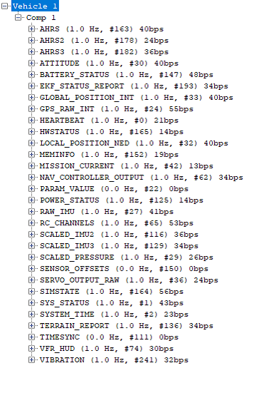
Here is the result on Mission Planner Mavlink Insector (As per Wiki : rates to “-1”) :
C) Send a SET_MESSAGE_INTERVAL:
We can now use the SET_MESSAGE_INTERVAL : This method provides the most precise control and reduces bandwidth requirements (because unnecessary messages are not sent) but requires knowing exactly which messages you require:
This is the command line we can add to the script above:
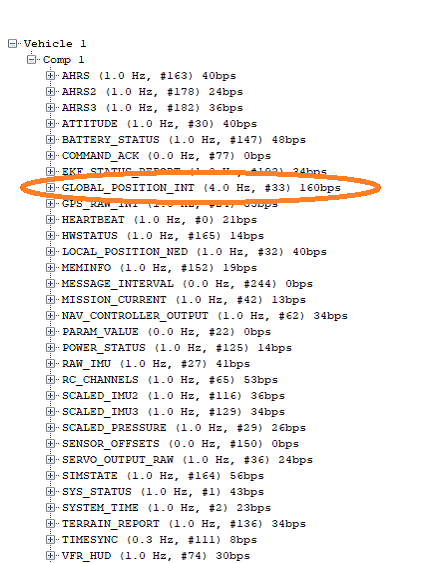
master.mav.command_long_send(master.target_system, master.target_component, mavutil.mavlink.MAV_CMD_SET_MESSAGE_INTERVAL, 0, mavutil.mavlink.MAVLINK_MSG_ID_GLOBAL_POSITION_INT, 250000 , 0, 0, 0, 0 ,0)
The message interval is in microseconds, so 250000 MicroSecs makes a 4 Hz message rate.
Here is the result on Mission Planner Mavlink Insector:
That concludes part 4 of this serie. This is a pivotal point in the experiments as we can now start adding onboard processing for the behavior of the vehicles. Having fine control of messages streams at the Flight Controller level will be key to add more vehicles and adding complexity to the flight configurations.
As usual, I am open for comments and explanations and I just hope you enjoy reading and experimenting with Swarming.
Other links of this series of blog:
Part 1
Part 2
Part 3
Part 4
Blog Image: Swarming and Teaming – Unleashing the Unmanned Force