
Robot swarms flying high over a rescue crew in remote locations could give the first responders a communication network to keep them connected. Laboratory of Intelligent Systems / EPFL
Wireless Network Architectures
In this second part we will explore the different network topologies in order to provide the best configuration for our experiments. So far we have worked with centralized communication architecture as shown in Figure 1, where all UAVs in the swarm are connected to the GCS.
The following is an extract from Review of Unmanned Aerial Vehicle Swarm Communication Architectures and Routing Protocols from Xi Chen, Jun Tang * and Songyang Lao:
Each UAV forms a one-to-one relationship with the infrastructure and directly receives control commands from the infrastructure. This type ofcentralized communication architecture is relatively stable, adopts simpler routing algorithms, and has a smaller scale. When the size of the UAV swarm and the coverage area of the mission are small and the mission relatively simple, this type of architecture is more suitable.
In a “single-group swarm Ad hoc network” (Figure 2), the communication between the swarm and the infrastructure is a single point link relying on a specific UAV called gateway UAV. In this system, other UAVs are relay nodes that forward data within the swarm. Using this method, UAVs in the swarm can share situation information in real time to optimize collaborative control and improve efficiency. Similarly, mutual communication between the gateway UAV and infrastructure also enables the upload and download of swarm information, including instructional information
Figure 3a depicts an example of ring architecture. UAVs in ring architecture form a closed communication loop through a bidirectional connection. Any UAV can act as the gateway node for the swarm. When a direct link between two adjacent UAVs fails, the target UAV can link back through the communication loop. Therefore, the ring architecture has a certain stability. However, it is clearthat this architecture lacks scalability. As shown in Figure 3b, communication is organized in the form of star architecture. The gateway UAV is in the middle, and not only communicates with the infrastructure but also with the entire UAV swarm. It is not difficult to see from Figure 3b that star architecture has the inherent disadvantage of a SPOF. That is, if the gateway node fails, it will cause the entire system to fail. Meshed architecture is a combination of ring and star architectures and has the advantages of both systems (Figure 3c). All the UAV nodes in the swarm have the same capabilities, with both terminal nodes and routing functions. The information stream from one node to another can be implemented in different forms, and any UAV can act as a gateway node for the swarm.


Testing with RPI as GATEWAY with MavProxy
Based on the above , we will implement a Gateway UAV with a Star Topology. This configuration architecture has some weakneness because the Single Point Of Failure but offers the benefit of being the easiest method to work with.
Setting up a Raspberry Pi as a routed wireless access point:
https://www.raspberrypi.org/documentation/configuration/wireless/access-point-routed.md
/etc/hostapd/hostapd.conf
country_code=CA (Put your Country code here)
interface=wlan0
ssid=LEADER
hw_mode=g
channel=7
macaddr_acl=0
auth_algs=1
ignore_broadcast_ssid=0
wpa=2
wpa_passphrase=ardupilot
wpa_key_mgmt=WPA-PSK
wpa_pairwise=TKIP
rsn_pairwise=CCMP
To allow for ESP-01 tests, keep the DHCP range below 10 so we can ‘‘reuse’’ the fixed IP address logic as SYSID 10 = 192.168.4.10 and so on.
sudo nano /etc/dnsmasq.conf
dhcp-range=192.168.4.2,192.168.4.9,255.255.255.0,24h
The RPI being now the Gateway, we need to SSH to it in order to monitor traffic and connections status Checking leases , allows us to check what address have been assigned by the DHCP:
cat /var/lib/misc/dnsmasq.leases
Connection to LEADER:
Using raspi-config or GUI interface set the Pi3 WIFI to connect to LEADER.
In order to get access to the Pi3, the Dev PC must be logged to LEADER as well
2 A) Testing with SITL using WIFI
Pi4-01 as Gateway : 192.168.4.1
Pi3-10 & Pi3-11 connected to Pi4-01 as DHCP clients
Dev PC on WIFI : 192.168.4.8 (may change; adjust accordingly)
Launch Pi3-10 and Pi3-11 and output signal to Pi4-01
./arducopter --model quad
mavproxy.py --master tcp:127.0.0.1:5760 --out udp:192.168.4.1:14550 (60)
On Pi4-01 Start Arducopter local and launch mavproxy with Forward Position:
./arducopter --model quad
mavproxy.py --master tcp:127.0.0.1:5760 --master=udpin:0.0.0.0:14550 --master=udpin:0.0.0.0:14560 --out udp:192.168.4.8:14570 --cmd=“set fwdpos 1”
On Dev PC, connect to RPI4 (either through Ethernet or with WIFI) and start MavProxy at 14570
mavproxy --master=udpin:192.168.4.8:14570 --console --map
As explained before, get into each of the Pi3 MavProxy sessions and Switch to Guided - Arm - Takeoff - and switch to Follow
Back to Dev PC Powershell MavProxy, select SYSID 1 : Guided - Arm - Takeoff - Guided using Map and enjoy the fly ![]()

2 B) Testing with SITL using WIFI and ESP-01
Pi4-01 as Gateway : 192.168.4.1
Pi3-10 & Pi3-11 connected to Pi4-01 using ESP-01
Dev PC on WIFI
As explained during DHCP configuration, we have reseved 192.168.4.10 and above for fixed adressing. So in order to have the ESP-01 connected, we have to change the SSID to LEADER and set adress in the 192.168.4.X range. Once that completed, we launch Pi3-10 and 11 with mavproxy connecting to the ESP-01 using the USB interface like in Part 1. Please note that we keed WIFI access on the Pi3 so that Dev PC can SHH to start SITL and Mavproxy using its own WIFI making a double architecture: Centralized Topology for the SSH and Star for the Telemetry.

Launch Pi3-10 and Pi3-11 using SSH over WIFI ( in the DHCP range)
./arducopter --model quad
mavproxy.py --master tcp:127.0.0.1:5760 --out /dev/ttyUSB0,115200
On Pi4-01 Start Arducopter and launch mavproxy with Forward Position:
./arducopter --model quad
mavproxy.py --master tcp:127.0.0.1:5760 --master=udpin:0.0.0.0:14550 --master=udpin:0.0.0.0:14560 --out udp:192.168.4.8:14570 --cmd=“set fwdpos 1”
On Dev PC, connect to RPI4 (either through Ethernet or with WIFI) and start MavProxy at 14570
mavproxy --master=udpin:192.168.4.8:14570 --console --map
As explained before, get into each of the Pi3 MavProxy sessions (using WIFI) and Switch to Guided - Arm - Takeoff - and Follow
Back to Dev PC Powershell MavProxy, select SYSID 1 : Guided - Arm - Takeoff
Here is an example with Pi3-10 Following Pi4-01 in CIRCLE mode, permitting longer automated tests for link quality and load qualification.The window with HTOP shows the load on the CPU that is quite acceptable, leaving room for more advanced stuff… ![]()
2 C) Testing with SITL using WIFI and SIK MultiPoint
https://ardupilot.org/copter/docs/common-sik-telemetry-radio.html
Pi4-01 as Gateway : 192.168.4.1
Pi3-10 & Pi3-11 connected to Pi4-01 using SIK MULTIPOINT
Dev PC on WIFI
While keeping the same network configuration we will experiments with a different set of radios.
As Tridge wrote when I asked for Telemetry options , “use a mesh radio setup, such as RFD900x with my mesh fw”.
I had a couple of SIK on hand ready to flash with Multipoint Firmware
https://ardupilot.org/copter/docs/common-3dr-radio-advanced-configuration-and-technical-information.html#common-3dr-radio-advanced-configuration-and-technical-information
With this code:
https://github.com/RFDesign/SiK/tree/SiK_Multipoint
The procedure is pretty straightforward but requires a Linux based system for flashing. The radio that I used do have the bootloader already flashed-in so you dont need the SiLabs USB debug adapter. Just “make” and upload to your radio using this python script located in /SiK/Firmware/tools and by specfying the port and radio type:
./uploader.py --port /dev/ttyUSB0 …/dst/radio-hm_trp.ihx
Then, you can connect to radio using a Terminal and set
(ex. picocom /dev/ttyUSB0 or AMA0 --b 57600 to quit Crtl-a x)
Node ID of Pi4-01 to 0
Node ID of Pi3-10 to 1
Node ID of Pi3-11 to 1 as well
S15: NODEID
MUST be a unique ID on the network, otherwise cross talk will occur Base ID is defined by setting to 0, this is the node that keeps the network in sync with all other nodes. When setting the the NODEID to the base (ie 0) it will always have link to it’s self thus link will never be lost.
And set Node Destination to 0
S16: NODEDESTINATION
This is where all the serial data recived on this node should be sent to. For example, to send all data to the base node only set this to 0. DEFAULT is 65535 which is broadcast to all nodes.
On the Pi3 the SIK radio will be connected directly to AMA0. In order to get full speed and control, we need to disable the bluetooth patch so the UART can be reassigned to AMA0, as explained here:
sudo nano /boot/config.txt
Add at the end of the file
dtoverlay=pi3-miniuart-bt
Launch Pi3-10 and Pi3-11 using SSH over WIFI ( in the DHCP range)
./arducopter --model quad
mavproxy.py --master tcp:127.0.0.1:5760 --out /dev/ttyAMA0,57600
On Pi4-01 Start Arducopter and launch mavproxy with Forward Position:
./arducopter --model quad
mavproxy.py --master tcp:127.0.0.1:5760 --master /dev/ttyUSB0,57600 --out udp:192.168.4.8:14570 --cmd=“set fwdpos 1”
On Dev PC, connect to RPI4 (either through Ethernet or with WIFI) and start MavProxy at 14570
mavproxy --master=udpin:192.168.4.8:14570 --console --map
As explained before, get into each of the Pi3 MavProxy sessions (using WIFI) and Switch to Guided - Arm - Takeoff - and Follow
Back to Dev PC Powershell MavProxy, select SYSID 1 : Guided - Arm - Takeoff
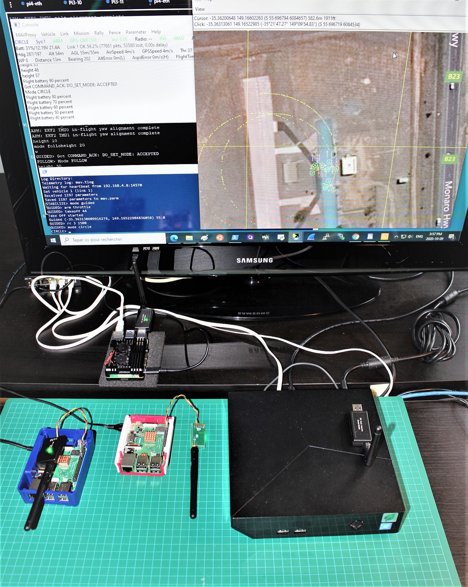
Here is the Lab setup showing the Pi4-01 connected to USB SIK Radio ( /dev/ttyUSB0) and the Pi3 with the OnBoard units directly connected to /dev/ttyAMA0, performing the CIRCLE - FOLLOW test. Looking at the Link quality, it show about 60% OK and that reflects on the map as there is some ‘‘dirt’’ in the vehicle tracking, a telltail sign of packets dropping. More experiments will be required to validate the use of this techonology on flying vehicles.

2 D) Testing with SITL using WIFI and XBEE MultiPoint
One again, we are keeping the same network configuration and switch to a different set of radios.
https://ardupilot.org/copter/docs/common-telemetry-xbee.html
and more specifically the XBee 3
https://www.sparkfun.com/products/15128
XBee 3 handles 802.15.4, and ZigBee, and BLE protocols and you can now talk to the modules over UART or SPI as well. With a 200ft indoor range, or 4000ft outdoor/line-of-sight range, you can set up a mesh network to communicate with various devices.
Using the XCTU DIGI Tool Utility , we set radios as MultiPoint using DIGIMESH 2.4 FirmWare:
Channel C
RAN ID 666
Standard Router for Pi4
End Points for Pi3 10 - 11

Transparent Mode
Baud Rate 57600 Bauds

Select point-to-multipoint, by setting the transmit options to 0x40.

Point-to-multipoint transmissions occur between two adjacent nodes within RF range. No route discovery and no routing occur for these types of transmissions. The networking layer is entirely skipped. Point-to-multipoint has an advantage over DigiMesh for two adjacent devices due to less overhead. However, it cannot work over multiple hops.
Testing
Pi4-01 as Gateway : 192.168.4.1
Pi3-10 & Pi3-11 connected to Pi4-01 using XBEE
Dev PC on WIFI
Launch Pi3-10 and Pi3-11 using SSH over WIFI ( in the DHCP range)
./arducopter --model quad
mavproxy.py --master tcp:127.0.0.1:5760 --out /dev/ttyAMA0,57600
On Pi4-01 Start Arducopter and launch mavproxy with Forward Position:
./arducopter --model quad
mavproxy.py --master tcp:127.0.0.1:5760 --master /dev/ttyUSB0,57600 --out udp:192.168.4.8:14570 --cmd=“set fwdpos 1”
On Dev PC, connect to RPI4 (either through Ethernet or with WIFI) and start MavProxy at 14570
mavproxy --master=udpin:192.168.4.8:14570 --console --map
Just like the SIK radio test, SSH into each of the Pi3 MavProxy sessions (using WIFI) and Switch to Guided - Arm - Takeoff - and Follow
On Dev PC: Powershell MavProxy, select SYSID 1 : Guided - Arm - Takeoff
Right from the start we can see the Link Quality going down to an unacceptable level. There is too much packet lost so in order to get a basic formation flying we have to reduce speed down to 3 Degs./Sec in CIRCLE mode so the Follower could keep the pace. For the moment this topology is not qualifying for inboard test.
That rise the question: Could a different method of handling messages would work better than the mavproxy reflector (set fwdpos 1) ? … We may find the answer in forthcoming Blogs ![]()

This concludes experiments for Part 2. As usual, I am open for comments and explications and your input are very welcomed. On the next Blog we will experiment with WIFI Multicast and proceed to the integration of the RaspBerry Pi on the UAV as Companion Computer Gateway for more Swarming experiments.
Other links of this series of blog:
Part 1
Part 2
Part 3
Part 4