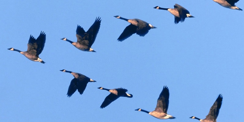
Geese fly in a V formation because it reduces the naturally occurring downward pull of gravity. When the birds fly behind one another, it creates free lift. In essence, it allows the birds to save energy.
WIFI MULTICAST
When I asked Andrew Tridgel (@tridge) what methods are available to publish the Leader Position Localisation over radio, here’s one of the answers:
“Use a multicast link, which gives you a shared transport.”
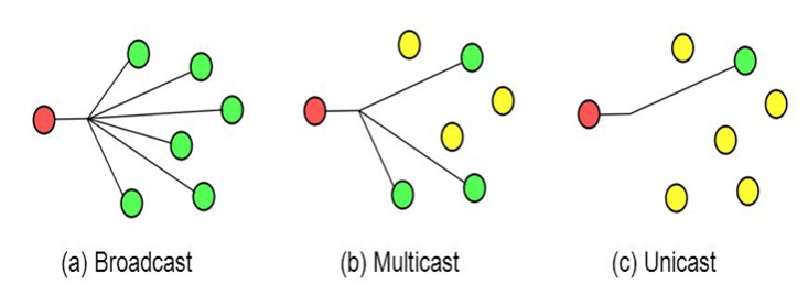
What is multicast?
In short, multicast is a means of sending the same data to multiple recipients at the same time without the source having to generate copies for each recipient. Whereas broadcast traffic is sent to every device whether they want it or not, multicast allows recipients to subscribe to the traffic they want. As a result, efficiency is improved (traffic is only sent once) and overhead is reduced (unintended recipients don’t receive the traffic).
More info here: Multicast over Wireless
https://radiocrafts.com/why-is-multicasting-becoming-essential-for-mesh-networks/
Examples of Multicast usage with ArduPilot

As demonstrated in real flight test by Tridge in the video above and using an adaptation of this Simulator -SITL- script:
ardupilot/libraries/SITL/examples/Follow/plane_quad.sh at master · ArduPilot/ardupilot · GitHub
The script is using mcast: as the default multicast mavlink socket  (239.255.145.50:14550)
UARTA="mcast:"

And start both instances of simulator by connecting to this socket
PLANE --model plane --uartA $UARTA
COPTER --model quad --uartA $UARTA
Demonstrated using Morsesimulator by @ashvath100
Using SITL with Morse — Dev documentation
ardupilot/libraries/SITL/examples/Morse/start_follow.sh at master · ArduPilot/ardupilot · GitHub

Demonstrated using AirSim Simulator by @rajat2004
Using SITL with AirSim — Dev documentation
ardupilot/libraries/SITL/examples/Airsim/follow-copter.sh at master · ArduPilot/ardupilot · GitHub

NOTE: For those who want to try the examples above on a Windows10 environment, there is an issue with MULTICAST on WSL2 as it restrict the usage to local address: 127.0.0.1, making the communication “non standard” . Traffic to multicast groups: IANA has reserved 224.0.0.0 – 239.255.255.255 for multicast groups, with 239.0.0.0/8 commonly used within private organizations.
PyMavLink default UDP multicast mavlink socket (mcast:) is 239.255.145.50:14550
Configurations and tests on RaspBerry pi:
A) Check if MULTICAST is enabled (it should be)
ip link show wlan0 | grep MULTICAST
B) Create route to wlan0 (This sets all of the class D (/4) Multicast routes to go via wlan0)
sudo route add -net 224.0.0.0/4 dev wlan0
C) Make route permanent
sudo nano /etc/network/interfaces
up route route add -net 224.0.0.0/4 dev wlan0
D) Check routes
ip route list
224.0.0.0/4 dev wlan0 scope link
If you are wondering why ping 224.0.0.1 (or any address in this class D) does not give you anything back it is because the ICMP to reply to broadcast/multicast ping message is disabled by default. To enable you need to edit /etc/sysctl.conf and set:
net.ipv4.icmp_echo_ignore_broadcasts = 0
Testing WIFI MULTICAST
Pi4-01 as Gateway : as Multicast Broadcaster
Pi3-10 & Pi3-11 connected to Pi4-01 Multicast signal
Dev PC on WIFI : 192.168.4.8 (may change; adjust accordingly)
On Pi4-01 Start Arducopter local and launch mavproxy with Forward Position:
./arducopter --model quad
mavproxy.py --master tcp:127.0.0.1:5760 --out udp:192.168.4.8:14570 –out mcast:
Launch Pi3-10 and Pi3-11 that read position from Leader Multicast address
Follower Pi3-10
./arducopter –uartA mcast: --model quad
mavproxy.py --master tcp:127.0.0.1:5763 --out udp:192.168.4.8:14550
Follower Pi3-11
./arducopter –uartA mcast: --model quad
mavproxy.py --master tcp:127.0.0.1:5763 --out udp:192.168.4.8:14560
Why are we starting ./arducopter --uartA mcast: ?
We feed the multicast message directly to the simulated vehicle by connecting to the console port (5760) and map mavproxy to uartC (5763) in order to publish on the GCS:
Starting sketch ‘ArduCopter’
Starting SITL input
Using Irlock at port : 9005
UDP multicast connection 239.255.145.50:14550
bind port 5762 for 2
Serial port 2 on TCP port 5762
bind port 5763 for 3
Serial port 3 on TCP port 5763
Home: -35.363262 149.165237 alt=584.000000m hdg=353.000000
Smoothing reset at 0.001
validate_structures:411: Validating structures
On Dev PC, connect to RPI4 and start mavproxy
mavproxy --master=udpin:192.168.4.8:14570 --console --map
As explained before, get into each of the Pi3 sessions and Switch to Guided - Arm - Takeoff - and switch to Follow
Back to Dev PC Powershell MavProxy, select SYSID 1 : Guided - Arm - Takeoff - Guided using Map and enjoy the fly ![]()
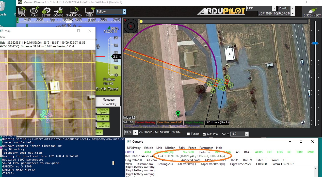
In the example below I have connected the Pi3 to Mission Planner. Note the link quality is quite acceptable considering the added Multicast signal.
INTEGRATION on QuadCopters
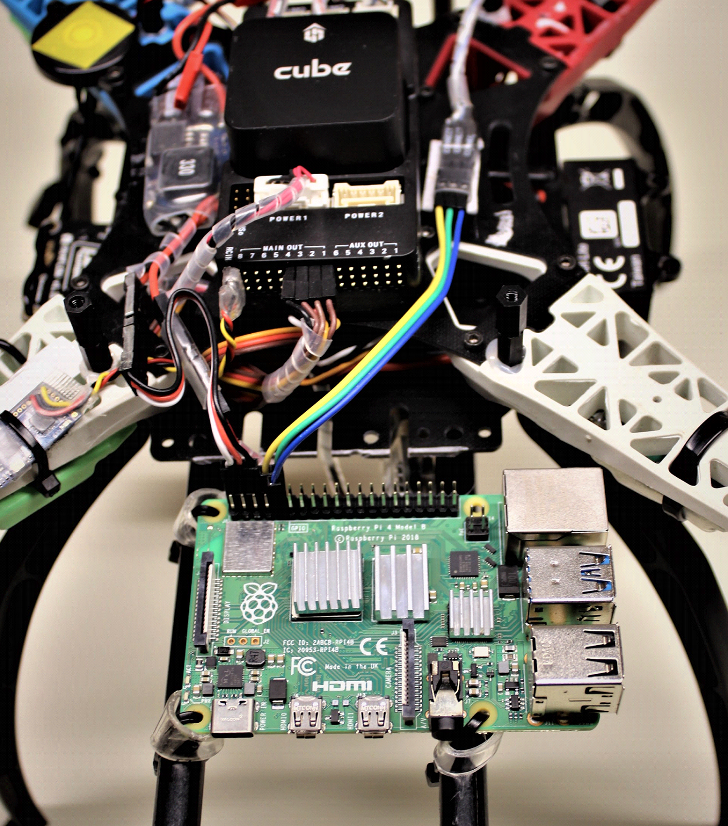
These pictures show how I installed and connected the Companopn Computers on my Vehicles
Flamewheel 450 with RaspBerryPi 4
this is the old “mule” that flew on so many experiments. It is cheap an ugly but it works just fine. The Pi is powered by a 5A Ubec located on left side of the CUBE and for this configuration, a connection on TTYAMA0 to Telemetry1 at 921600 Bauds (see Part 2 how to disable the bluetooth patch). The installation allows insertion and removal just by sliding ZipTies and transparent tubes and for easy connection to Keyboard - Monitor - Ethernet if needed.
Flamewheel 330 with RaspBerryPi Zero,
this is a collection of Hardware, Software*… and Tupperware…* as the protector is made of a Lemonade Jar :-). The RPI Zero is fixed using double sided foam tape with a FTDI siting on top with the same technique. This allows for interconnection to TELEMETRY or other devices like ESP-01 or SIK or XBee using AMA0 or USB0 at sppeds up to 921600 Bauds.
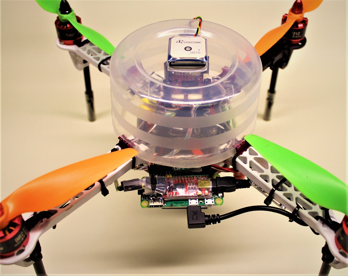
This type of installation is well suited for making different experiments as it allows for fast and easy modifications. I use a lot of doubleface foam tape, zip ties and transparent heatshrink that let you visually inspect connections and confirm signal by looking at the FTDI LEDS for example.
Visual BEACON,
for some of the SCRIPTING experiments (next Chapter) I can visually confirm that the Leader Position Signal is received and processde by the Follower. This is done by “deadbug” installation of a MOC8050 Photodarlington Optocoupler driven by RPI Zero GPIO 21 with 2.2 kOhm current limiter and driving a high power multi facetted 12 Volts LED.

This concludes the first part of this series of Blogs, where the existing methods of communication have been demonstrated and tested. A special thank to Tridge for his guidance, making my researchs for solutions more efficient.
In the next series, we will explore more specific techniques for Smarming communication and infrastructure. As usual, I am open for comments and explanations.
Other links of this series of blog:
Part 1
Part 2
Part 3
Part 4