
I do a lot of smaller copter tuning and I know it’s hard. In fact many of the features I have developed have been primarily targeted at making smaller copters work better - why should BetaFlight have all the fun.
I therefore proposed to the investment committee that I do a series of standard builds so that people could basically copy the setup and quickly and easily get a really great ArduCopter experience. This is the result.
The meat of the content is contained in a series of youtube videos that I will describe here.
Parts list:
- iFlight Titan Chimera7 LR
- XING 2806.5 1300KV Motor x4
- Lumenier LUX H7 HD Ultimate / Matek H743 Slim
- TBS UNIFY 5G8 PRO32 HV
- TBS Tracer RX
- Gemfan 7040 x4
- RunCam Phoenix 2 JB Edition
- Matek M8Q-5883
- TBS Triumph Pro LR
- TBS Tracer Sleeve Dipole x2
- T-Motor F55A F3 Pro II 4-in-1 ESC
- Turnigy Graphene Panther 3000mAh 6S 75C
Final tune here: Chimera7-Tuned4.1-FinalCutPro.param (25.7 KB)
DJI 4.2 tune here: Chimera7-Tuned4.2-DJI.param (25.5 KB)
DJI 4.3 retune here: Chimera7-Tuned4.3-DJI-Tune3.param (26.2 KB)
1. Intro and Unboxing
The first video at the top is unboxing the iFlight Chimera 7 frame, Matek M8Q-5883 GPS, T-motor F55A PRO II F3 4-in-1 ESC and Lumenier LUX H7 HD Ultimate Flight Controller
2. Base plate assembly
Building the Chimera 7 base plate assembly

3. Frame and component placement
Upper frame assembly of the Chimera7 and a dry run of component placement so that the cable runs can be of the right length and are connected to the right points on the flight controller.

4. Initial firmware load
Initial ArduCopter firmware load on the Lumenier Lux HD H7 using dfu-util and Mission Planner
http://dfu-util.sourceforge.net/releases/
FRAME_TYPE=1

5. ESC setup
Wiring and configuration of the T-Motor F55A F3 Pro II ESCs
SERIAL5_PROTOCOL=16 # ESC telemetry
PWM_TYPE=6          # DShot600
SERVO_BLH_AUTO=1    # BLHeli passthrough
Use BLHeliSuite to make sure BLHeli32 32.8 or later is installed
SERVO_DSHOT_ESC=1   # DShot commands
NTF_LED_TYPES=2305  # DShot LEDs

6. Flight Controller and Peripheral Wiring
Wiring all the peripherals (GPS, Camera, VTX, Tracer) to the flight controller

7. Peripheral configuration
Configuring all of the peripherals with Mission Planner
Put the VTX into CRSF mode, could also use AgentX to configure
Put the camera into UART control mode
Use AgentX to configure Tracer outputs 1(TX) & 2(RX) and 3(RX) & 4(TX) as CRSF, switch to 12-channel mode and update RX
Configure serial ports:
SERIAL1_PROTOCOL=23 # RC input (UART7)
SERIAL3_PROTOCOL=5  # GPS (UART2)
SERIAL2_PROTOCOL=26 # RunCam (UART1)
CAM_RC_TYPE=1       # RunCam 5-key OSD camera
Calibrate radio and compass

8. VTX and Yaapu configuration
Configuring VTX power and Yaapu telemetry passthrough
Setup VTX to be controlled by flight controller (RX)
VTX_ENABLE=1   # VTX control
RC11_OPTION=94 # VTX power
RC_OPTIONS=288 # Yaapu passthrough

9. GPS, VTX and camera mounting
Mounting the GPS, VTX and Camera to the Chimera 7 frame

10. Power train unboxing and plan
Unboxing the 6S 3000mAh 75C battery, iFlight 2806.5 1300KV motors and planning the motor and ESC installation.
Neopixel and buzzer installation.

11. Motor dry mount
ESC pigtail soldering. 6S power test. Fixing motors temporarily to enable soldering.

12. Motor soldering and motor test
Soldering the motors to the ESCs and then testing the motors

13. Final frame assembly
Conformal coating of exposed connections. Heatshrink protection of tracer and installation of immortal T antenna. Final installation of ESCs, motors, flight controllers and peripherals into the frame. Addition of foam to protect barometer.
See video 22 for antenna adjustments using sleeve dipoles for much better radio range

14. Initial configuration, ready to arm
Reset level in mission planner.
Configured custom compass orientation setup and calibration:
COMPASS_CUS_YAW=180 # custom compass yaw of 180
COMPASS_CUS_PIT=-15 # custom compass pitch of -15
COMPASS_ORIENT=100  # custom compass orientation
COMPASS_AUTO_ROT=0  # turn off compass auto rotation
Performed a compass calibration and checked that EKF status indicator in mission planner did not get too high.
Checked motor order and direction and configured correctly by setting frame type to betaflight:
FRAME_TYPE=12       # set motor order to betaflight/X
SERVO_BLH_RVMASK=6  # reverse motor channels 2 and 3
Radio calibration. Setup motor emergency stop, initial flight modes and radio failsafe:
RC9_OPTION=31       # motor estop
FLTMODE1=1          # acro mode
FLTMODE5=2          # althold mode
FLTMODE6=16         # poshold mode
FS_THR_ENABLE=3     # land on radio failsafe
SD card installation. First arming and motor test checking that MOT_SPIN_MIN/MOT_SPIN_ARM is low enough:
MOT_SPIN_MIN=0.03   # minimum output when throttle raised
MOT_SPIN_ARM=0.02   # output when armed
Verify motor emergency stop.
15. Current Calibration and Bi-Directional DSHOT Setup
Calibrate current sensor using an in-line ammeter. Set BAT_AMP_PERVLT. Setup bi-directional dshot using SERVO_BLH_BDMASK. Reduce SERVO_BLH_TRATE since rpm information is now coming from bi-directional dshot.
Update - my friend @juzzle1 kindly did a proper full range current calibration of the ESC and flight controller and came up with a very linear response:
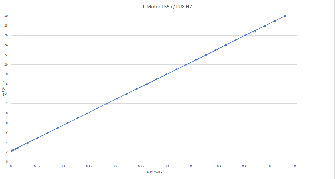
The updated settings are given below. Note that the offset means that the current sensor always reads 2.3A at zero throttle, but the rest of the response is very good.
BAT_AMP_PERVLT=52.706 # better current estimate
BATT_AMP_OFFSET=-0.04308
SERVO_BLH_BDMASK=15   # enable bi-directional dshot on all four channels
SERVO_BLH_TRATE=5     # lower telemetry update rate

16. Initial tune and notch configuration
Initial tune setup using Mission Planner setup wizard (Alt-A). Checking INS_GYRO_FILTER and ATC_RAT_RLL/PIT_FLTD. Check initial PIDs and enable the harmonic notch filter using ESC telemetry. INS_HNTCH_ENABLE set and INS_HNTCH_MODE to ESC telemetry. Make sure harmonic notch ratio of INS_HNTCH_FREQ amd INS_HNTCH_BW is correct. Set INS_HNTCH_REF. Setup INS_HNTCH_OPTS to track individual motors and loop rate. Increase SCHED_LOOP_RATE. Set SERVO_DSHOT_RATE to multiple of loop rate.
BATT_ARM_VOLT=22.1    # 6S setup
BATT_CRT_VOLT=21      # 6S setup
BATT_LOW_VOLT=21.6    # 6S setup
MOT_BAT_VOLT_MAX=25.2 # 6S setup
MOT_BAT_VOLT_MIN=19.8 # 6S setup
MOT_THST_EXPO=0.6     # expo for 7" props
INST_GYRO_FILTER=70   # gyro filter for 7" copter
ATC_RAT_RLL_FLTD=35   # d-term filter for 7" copter
ATC_RAT_PIT_FLTD=35   # d-term filter for 7" copter
INS_FAST_SAMPLE=3     # fast sampling on both IMUs
INS_HNTCH_ENABLE=1    # harmonic notch on
INS_HNTCH_FREQ=60     # lowest harmonic notch frequency
INS_HNTCH_BW=30       # bandwidth half of notch frequency
INS_HNTCH_MODE=3      # ESC notch updates
INS_HNTCH_REF=1       # required for ESC updates
INS_HNTCH_OPTS=6      # notch updates at loop rate and notch-per-motor
SCHED_LOOP_RATE=800   # gives finer control
SERVO_DSHOT_RATE=2    # dshot output at 1.6Khz

17. Pre-flight checks and first flight
Props on and initial hover test. Check copter does not have too much thrust at MOT_SPIN_ARM/MOT_SPIN_MIN. Reverse pitch. Reduce PIDs by 50% to remove hover oscillation. First log download to verify that the harmonic notch is tracking the motor RPM correctly. Check that motors outputs are similar and the copter is balanced. Check motor pole count. Check RATE output is below 10% oscillation. It’s also worth checking VIBE. Hover thrust is measured as a percentage of MOT_SPIN_MIN - MOT_SPIN_MAX. Ground effect compensation is switched on by default.
RC2_REVERSED=1 # reverse pitch input
iFlight motor configuration: https://shop.iflight-rc.com/xing-x2806-5-fpv-nextgen-motor-pro1001
WARNING: IT’S GENERALLY NOT A GOOD IDEA TO DO THE INITIAL HOVER TEST INDOORS ON A COPTER OF THIS SIZE

18. Precise IMU and compass calibration
Accel calibration with board mounted in frame. Temperature calibration of IMUs using INS_TCAL_*. Temperature calibration of barometer. Compass calibration with battery attached. Compass motor calibration with smaller props on upside down and rotated one position round.
INS_TCAL1_ENABLED=2 # enable first IMU temperature calibration
INS_TCAL1_MIN=5     # calibrate from 5C
INS_TCAL1_MAX=45    # calibrate until 45C reached
INS_TCAL2_ENABLED=2 # enable second IMU temperature calibration
INS_TCAL2_MIN=5     # calibrate from 5C
INS_TCAL2_MAX=45    # calibrate until 45C reached
TCAL_ENABLED=1      # enable baro temperature calibration
Note that its probably better to put the copter in the fridge for temperature calibration to avoid temperature stress.
The compass interference proved very problematic in practice and in the end I opted for a second external compass at the front of the vehicle. The rear compass interference can be reduced by holding the lead vertically away using a battery strap.

19. First flight - Stabilize, AltHold, PosHold and Autotune
First flight. Determined suitable hover thrust value (MOT_THST_HOVER) from log. Enabled autotune on RC8. Reduced AUTOTUNE_MIN_D. Set battery capacity. Set low battery capacity to 20% of full charge. Turned off battery failsafe. Cycled through stabilize/althold/poshold in flight. Autotuned roll/pitch first followed by yaw using AUTOTUNE_AXES. Post-tune increased filter values and set better althold parameters. Ran autotune again on all axes.
RC8_OPTION=17         # autotune on channel 8
AUTOTUNE_AXES=3       # only tune roll and pitch
AUTOTUNE_MIN_D=0.0003 # lowest d-term
BATT_CAPACITY=3000    # battery capacity
BATT_LOW_MAH=600      # battery failsafe low capacity at 20%
BATT_FS_CRT_ACT=0     # don't do anything on failsafe
BATT_FS_LOW_ACT=0     # don't do anything on failsafe
MOT_THST_HOVER=0.14   # hover thrust
INS_ACCEL_FILTER=10   # IMU accelerometer filter
PSC_ACCZ_P=0.14       # vertical P gain at hover thrust
PSC_ACCZ_I=0.28       # vertical I gain at double hover thrust

20. RTL, RC failsafe and propwash testing
RTL and throttle failsafe testing:
- Setup RTL on a switch via RC8_OPTION = 4; Changed the RTL altitude to 20m via RTL_ALT; Setup throttle failsafe to RTL via FS_THR_ENABLE = 1
- Hovered in PosHold and then switched to RTL via switch
- Hovered in PosHold and then did radio failsafe test by switching off the transmitter
RC8_OPTION=4       # RTL on a switch
RTL_ALT=2000       # RTL at 20m
FS_THR_ENABLE=1    # RTL on radio failsafe
LOG_FILE_DSRMROT=1 # start new log on arming
INS_LOG_BAT_OPT=1  # sample-rate FFT logging
INS_LOG_BAT_MASK=3 # FFT logging on both IMUs
LOG_BITMASK=178175 # fast attitude logging
Propwash testing:
- Checked for propwash by gunning the throttle so that the copter goes straight up and then dropped the throttle to zero and allowed the copter to fall in the propwash looking for instability
Vibration and log analysis:
- Did a hover test for with LOG_BAT_OPT=1 to get pre-filter sensor rate logging for FFT analysis
- Set LOG_FILE_DSRMROT to get a log per flight
- Look at ATT values for quality of the tune and RATE values for noise in the control loops. Looking - for less than 10% noise
- Look at VIBE to check that vibrations and clipping are not too high
- Looked at FFT graph to check on raw noise coming into the IMUs

21. FPV and Acro tuning
Setup for Acro:
- Airmode on via ACRO_OPTIONS = 1
- Increase roll and yaw rates via ACRO_RP_P = 10 and ACRO_YAW_P = 10
- Increase rate at stick edges via ACRO_RP_EXPO = 0.4
- Enable flips and rolls via ACRO_TRAINER = 0
Setup for OSD:
- Enable parameter configuration screens via OSD5_ENABLE = 1 and OSD6_ENABLE = 1
- Enable switch between three screens on 3-pos switch by setting OSD_CHAN = channel, OSD_SW_METHOD = 1 (PWM), OSDn_CHAN_MIN and OSDn_CHAN_MAX
- Enable RSSI display via RSSI_TYPE = 3
Flew in acro and it flew pretty well
Did some log analysis on the quality of the tune by looking at compass interference, RATE outputs and friends. Concluded that I needed another external compass mounted away from the battery pigtails
ACRO_OPTIONS=1     # enable airmode in acro
ACRO_RP_EXPO=0.4   # faster rotation at stick edges
ACRO_RP_P=10       # 450 degrees/s on roll and pitch
ACRO_YAW_P=10      # 450 degrees/s on yaw
ACRO_TRAINER = 0   # allow copter to fully roll past 45 degrees lean
ATC_INPUT_TC=0.08  # super crisp feel on pilot input
OSD5_ENABLE=1      # enable first OSD parameter screen
OSD6_ENABLE=1      # enable second OSD parameter screen
OSD_CHAN=7         # RC7 to switch OSD screens
OSD_SW_METHOD=1    # switch OSD screen on PWM values
OSD1_CHAN_MIN=900  # OSD1 around PWM 1000
OSD1_CHAN_MAX=1100
OSD5_CHAN_MIN=1400 # OSD5 around PWM 1500
OSD5_CHAN_MAX=1600
OSD6_CHAN_MIN=1900 # OSD6 around PWM 2000
OSD6_CHAN_MAX=2100
RSSI_TYPE = 3      # RSSI from radio receiver

22. Acro flips and rolls, antenna adjustments
Selected MPU 6000 by setting EK3_PRIMARY = 1. Switched immortal T’s for monopoles at the back. Re-tested acro with flips and rolls. All worked fine and range was much improved. Analysis of the logs showed low vibrations and reasonable RATE levels. After test flights installed sleeve dipoles to increase the range.
EK3_PRIMARY=1 # use MPU600 as the primary IMU

23. Measuring frame resonance with on-board FFT
Enabled on-board FFT via FFT_ENABLE=1. Set the FFT frequency range using FFT_MINHZ=16 and FFT_MAXHZ=950. Enabled disarmed logging via LOG_DISARMED=1. The flight controller and frame was mounted on a vibration speaker and then multitone pro was used to generate a sin sweep signal from 5Hz to 1Khz. The log was then analyzed to find high Y energy (FTN2.0.EnY) at 167Hz with 20Hz bandwidth and 236Hz with 60Hz bandwidth. Thus it makes sense to configure a static notch at 167Hz via INS_NOTCH_ENABLE=1, INS_NOTCH_FREQ=167, INS_NOTCH_BW=20.
Leonard castigated me for doing this test without the battery attached as that dramatically affects the resonance. So I repeated it and this time got resonance at 250Hz. However, after a lot of in-flight testing I settled on 150Hz to kill the rate output resonance that I was seeing.
FFT_ENABLE=1       # enable onboard FFT engine
FFT_MINHZ=16       # lowest FFT detection frequency
FFT_MAXHZ=950      # highest FFT detection frequency
INS_NOTCH_ENABLE=1 # enable static notch
INS_NOTCH_FREQ=150 # notch at 150Hz
INS_NOTCH_BW=75    # bandwidth of 75Hz

24. Getting The Perfect Tune
A long one this, but hopefully worth it!
Getting a perfect tune requires two things:
- Successive autotunes at different filter settings to determine optimal filter for roll and pitch
- Manual tune of yaw D
Successive autotunes
- Try different values of INS_GYRO_FILT, ATC_RAT_RLL_FLTD and ATC_RAT_PIT_FLTD, e.g. 40/20, 60/30, 80/40, 100/50, 120/60, 150/75
- Want highest filter setting that does not introduce significant noise and lowest filter setting that does not affect control.
- Control can be determined by looking at ATC_RAT_RLL_P/ATC_RAT_PIT_P values from autotune - higher is better. Once noise is dominating higher filter settings will not increase _P
- Noise can be determined by looking at RATE.POut/RATE.ROut in logs, needs to be below 0.1
Final autotune
- On the Chimera7 150/75 was found to be the best balance of noise and latency/control
- Final autotune at 0.075 AUTOTUNE_AGGR to produce very stable PIDs with high control
INS_GYRO_FILT=150   # Gyro low pass filter
ATC_RAT_RLL_FLTD=75 # Roll D-term filter
ATC_RAT_PIT_FLTD=75 # Pitch D-term filter
AUTOTUNE_AGGR=0.075 # Auotune aggressiveness
Yaw manual tune
- autotune does not touch ATC_RAT_YAW_D, it has to be tuned manually
- Set ATC_RAT_YAW_FLTD to optimal value from final autotune for roll/pitch
- Try values for ATC_RAT_YAW_D from 0.0001 in steps of 1000% until oscillation observed - so 0.0001, 0.001, 0.01, 0.1
- At oscillation reduce in steps of 10% until no oscillation - 0.1, 0.09, 0.08, 0.07, 0.06, 0.05, 0.04, 0.03 and then reduce another 25% - 0.02
- Tune ATC_RAT_YAW_FLTD by changing and repeating manual process
- On the Chimera7 ATC_RAT_YAW_FLTD = 60 / ATC_RAT_YAW_D = 0.02 was found to give best balance
ATC_RAT_YAW_FLTD=60 # Yaw D-term filter
ATC_RAT_YAW_D=0.02  # Yaw D
Yaw maximum acceleration
- Remove acceleration constraints - ACRO_YAW_P = 15 or ACRO_YAW_RATE = 600 and ATC_ACCEL_Y_MAX = 0
- Do a fast yaw maneuver
- In the log measure the observed RATE.Y acceleration. Calculate acceleration from MAX(RATE.Y) - MIN(RATE.Y) / T. Multiply by 100 to get centidegrees/s/s and set ATC_ACCEL_Y_MAX to this value
- For the Chimera7 this resulted in ATC_ACCEL_Y_MAX = 72000
ATC_ACCEL_Y_MAX=72000 # Maximum Yaw acceleration
The final tune parameters are attached at the top of this post. A couple of extra goodies:
ATC_RAT_YAW_FF=0.0043 # Feed forward for yaw. Don't ask me how to calculate this
ACRO_Y_EXPO=0.6       # higher yaw expo
ACRO_RP_EXPO=0.6      # higher roll/pitch expo

25. Fun With Compasses
Show how to mount and configure an external compass:
https://www.aliexpress.com/item/1005001621715840.html
or
https://www.aliexpress.com/item/32648847326.html
Only use one compass, only use one IMU/EKF and make sure the current sensor is properly calibrated for best results

26. Final Flight(s)
")
