I want to build Rover based on SpeedyBee F4 V3 controler.
Please, advice me next steps or way to solve issue with connectivity between SpeedyBee board and EP1 radio.
I’m new in ardupilot (but with some experience in embedded tech), and want to setup SpeedyBee board as controller for the Rover.
Info:
SpeedyBee F4 V3 - controler
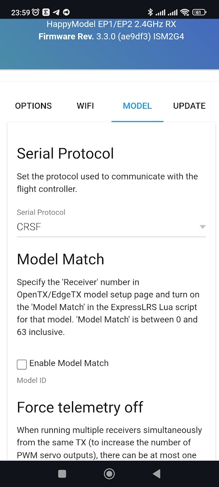
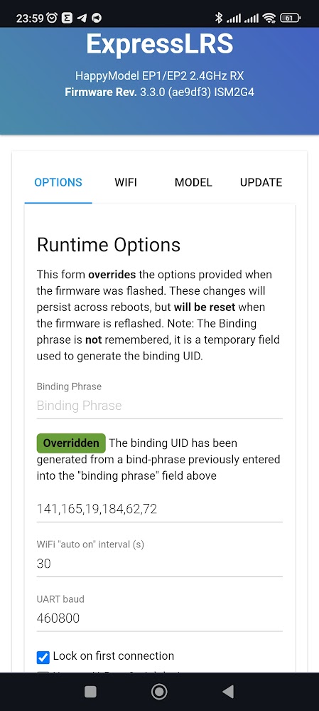
Happymodel EP1 TCX0 radio module
Rover V4.4.0 firmware
ELRS radio (CRSF protocol)
Сonfiguration (in missionPlanner, SpeedyBee board)
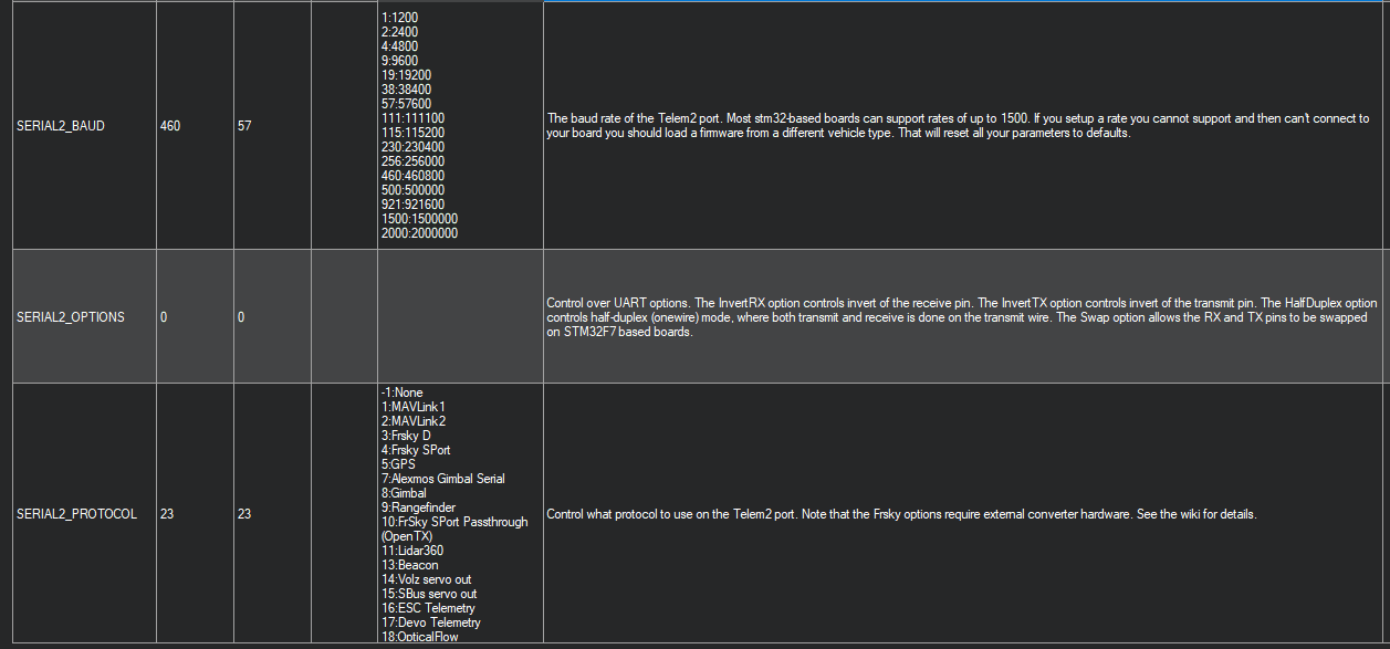
SERIAL2_PROTOCOL 23 (RCIN)
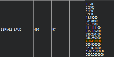
SERIAL2_BAUD 115 (115200 same as on radio module)
RSSI_TYPE 3 (ReceiverProtocol)
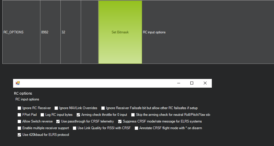
RC_OPTIONS 512 (Suppress CRSF mode/rate message for ELRS systems )
What I alredy done:
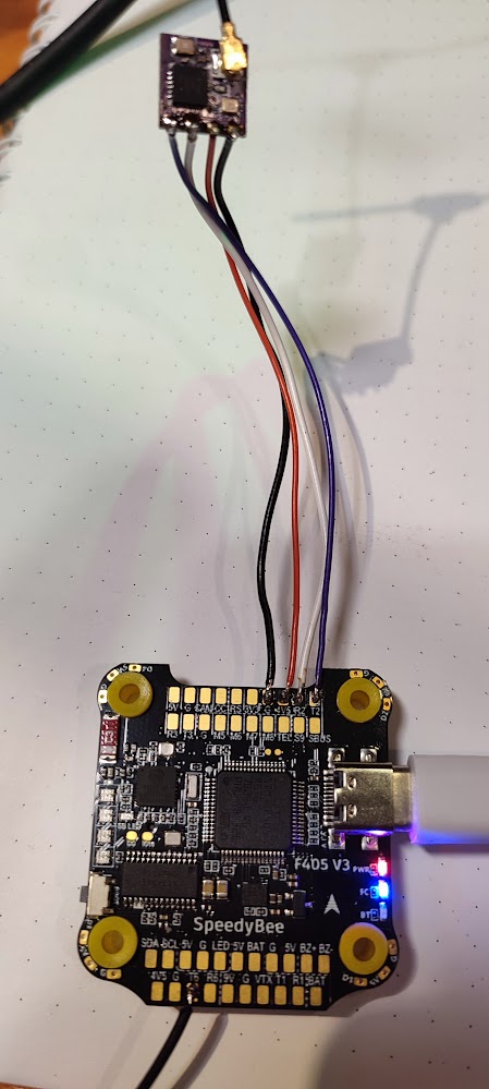
Soldered EP1 radio to SpeedyBee board.
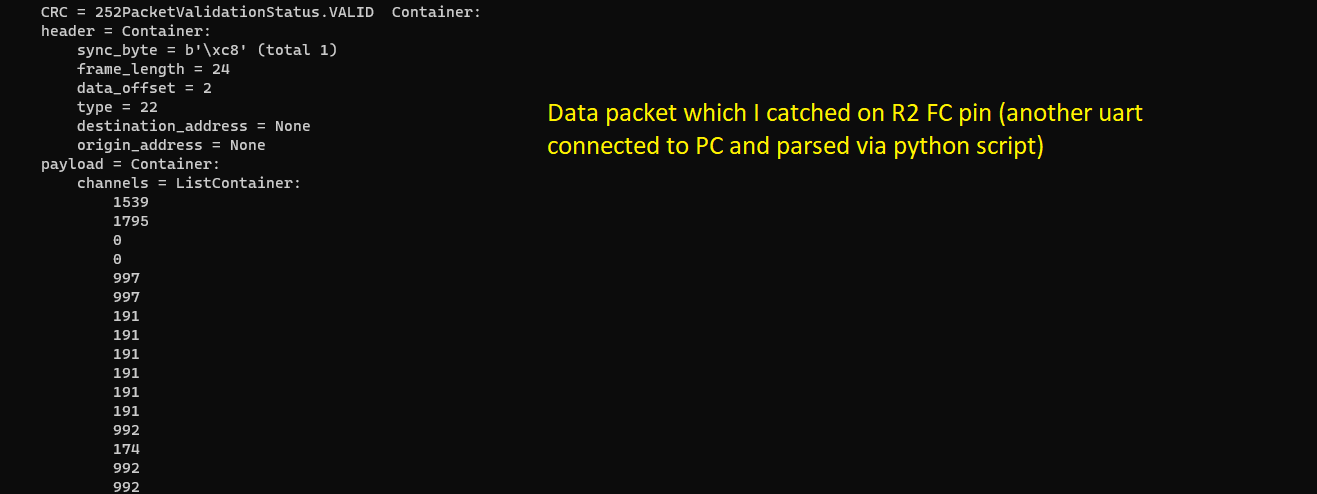
Set up all radio setting and verified that succefully receive data from radis module on R2 pin on SpeedyBee board (I’m using UART2) For verification I used UART->USB converted and succefuly parsed data on R2 pin (used python script)
After this all, in logs I still receiving zero in all channels
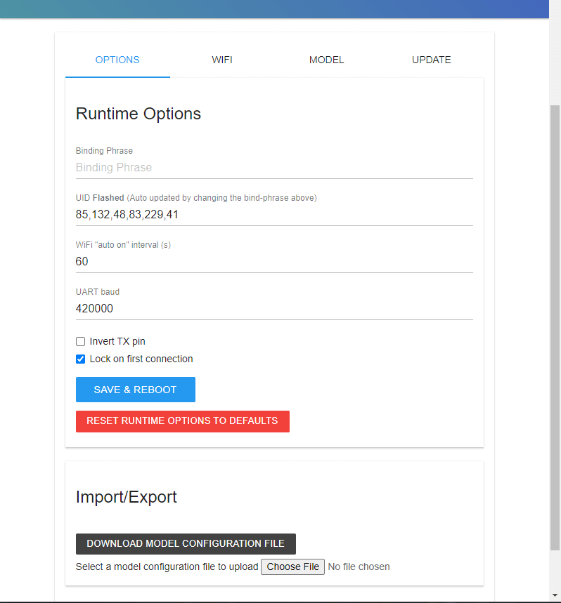
For ELRS you also need RC_OPTIONS bit 13 (value 8192, “Use 420kbaud for ELRS protocol”) for the right baud rate and I would recommend bit 5 (value 32, “Arming check throttle for 0 input”), resulting in RC_OPTIONS = 8736
That’s at least what it sais in the wiki and it worked for me and two other people I was helping so far…
On the other hand, I never used bit 9 (512) before
Without bit 9 it would be RC_OPTIONS = 8224
Did you also connect to the T2 Pin on the FC as written here?
Maybe I should set some debug print info somewhere in code for debugging? now I’m able to build and run on my firmware (currently I’m using Rover 4.4.0)
Completely wrong. You checked the bitmask to use 420k. We told you to do that, as it is the default behavior. And I literally told you to set 420k on your receiver yesterday.