Solar Rovers - trying to run Ardupilot indefinitely

The main goal is for it to stay outside indefinitely without losing communications or control of any part of it. since it’s a test bed for a boat that will be out of reach it needs to be able to handle any error or fault without physical intervention.

main components consist of
Ardupilot Matek H743 Wlite
mLRS 868mhz on a pair of FRsky R9 modules for RC and backup mavlink telemetry connection
Here+ M8p GPS/compass
LD06 Lidar
FMK24 5200 RADAR
AMB82-mini AI Camera board
hall sensors of the center board are connected to the flight controller so they can be used as wheel encoders,
Samsung A21s phone running Andruav with dual sim cards in tilting gimbal.
soyes xs16 phone in 2 axis servo gimbal.
48v 20ah ebike battery
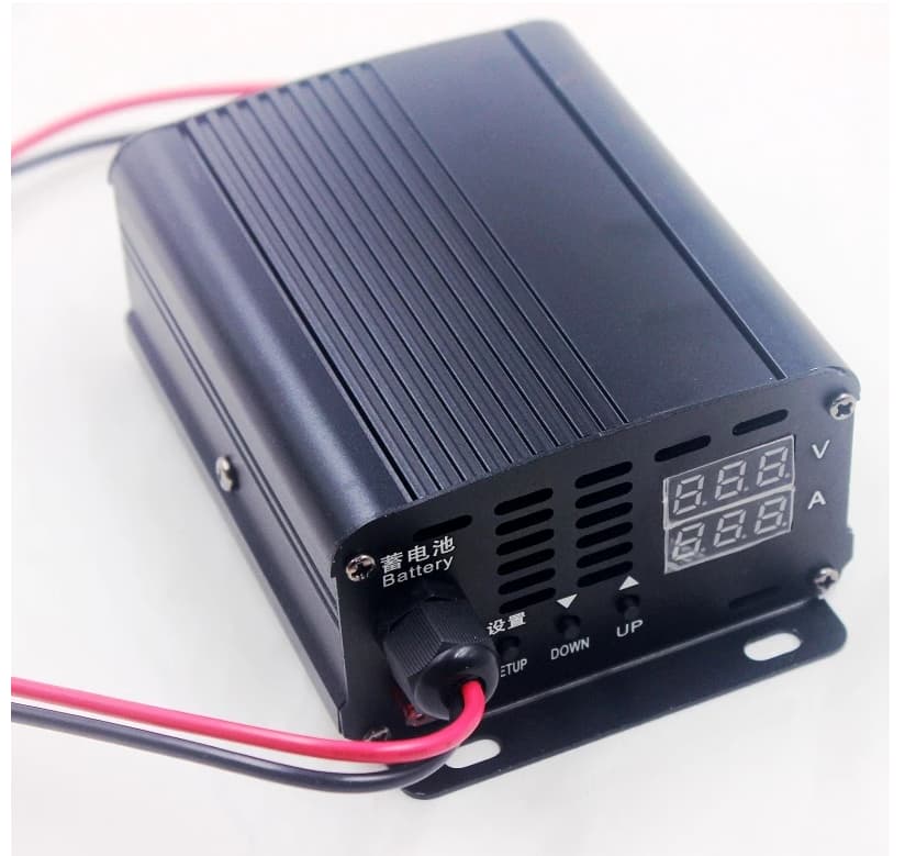
mppt charge controller

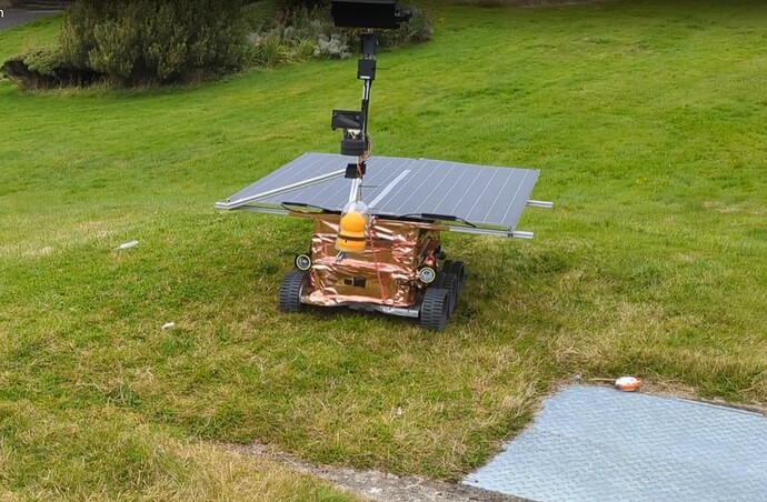
The first step was building a rover that could handle outdoors, The problem where I am is it rains just about every second day so everything has to be waterproof. the chassis is built around stacking plastic euro crates, these are 600x400mm and are standardized so you can take different crates and stack them up like Lego with each crate having a set of components, in the bottom one I have all the drive components, and electronics, further contained in Tupperware containers. The center crate has the batteries and the top one has the sensors and solar panel attached to it. the gold foil is just for the Mars rover look :smile:

For propulsion, it uses hoverboard motors, which are cheap with lots of torque and the controllers can be flashed for use with Ardupilot.

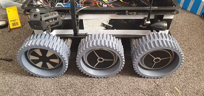
the wheels are 3d printed to give maximum traction on the soft sand.
b1da6246612d095c4fa0370b1ead02590fad6532_2_690x326

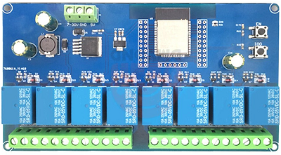
One of the main goals of this year has been power management. When I was testing last year even with a 48v 20ah battery it was struggling to stay alive, with motor controllers being on the rover would use almost 50W at idle so all it took was a rainy day and the battery was flat in a day. I added a relay bank so it could switch off components automatically now like the motor controllers, sensors and flight controller. It brings the power consumption down to less than 10w with just an esp32 and a pair of mobile phones left running.

It has 2x 100w solar panels connected to a MPPT charge controller that charges a 48v 20ah Ebike battery. because it rains so much meaning there is very little direct sunlight it needs to be able to reduce its power consumption a lot for it to be able to survive the night. when I tested it last year I was having a lot of problems with it running out of power during the night, so I have improved the power management so it can power off everything non-critical and added 2x backup batteries, one for the phones and one for the esp32 so I can still monitor it even when the main battery is flat. the flight controller uses a Matek 150a hall sensor for monitoring power consumption but im going to swap that out for a pair of the CAN node sensors to simplify wiring and let me monitor solar power generation.

The motor controllers were the biggest culprit for idle power consumption with the 3 controllers using almost 30W at idle.
The flight controller, lidar, AI camera, RADAR, WIFI camera only use around 10w, but even with that off its still using 10w to run the phones and esp32. I would like to turn the phones off at night but I don’t have an easy way of remotely turning them back on so I have been looking at moving to a PI controller instead of phones , then I could turn everything off and put the esp32 to sleep bringing power consumption under a watt.

The esp32 main controller is where most of my time has gone. this is the main management controller for the vehicle so it has a few functions:

Receives commands over the internet to my server using JSON.
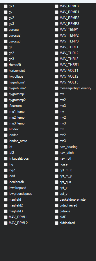
Reads Mavlink and converts to json values so I can log all the telemetry and receive alerts to my phone if anything goes out of range.
Monitors all the batteries using its adc inputs since I can’t read it from the flight controller when its off.
Relay control so it can cut power to all the other parts of the vehicle to save power.
Send some basic commands to the flight controller like change mode or arm/disarm
UPS backup battery so even if the main battery runs out the ESP32 will still have power.
It can read from an RC input channel so i can use my RC transmitter to trigger actions
and control all the lights, the rover has low beam, high beam, left turn, right turn and hazard lights.

one of the main issues I ran into last year was Ardupilot going strange after being on outside for weeks at a time, things like finding the artificial horizon spinning possibly due to temperature fluctuations and h743 controllers can corrupt their settings if the power is not switched on fast enough like when the battery runs out or gets slowly charged. so now the esp32 now controls power to the flight controller so all the voltages are stable before the flight controller is switched on, it is then switched off before the voltage gets too low, this has stopped the corruption issue I was having and now it can be restarted if I find the gyros spinning. I might look into a cube for a temperature-stabilised IMU, it might be able to run for longer before it starts spinning.
esp32_relay_x8_front

45a326008c9a054b7cea387c28fe5b861a0a2285_2_690x429

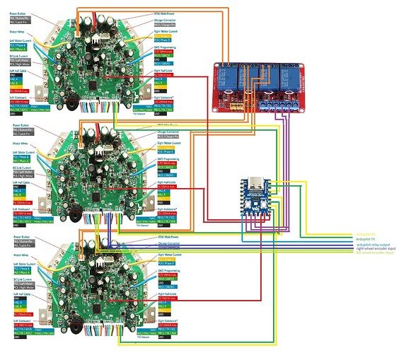
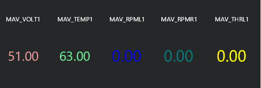
To control each hoverboard I’m using a RP2040 to read servo output mavlink data from the flight controller and convert that to RPM commands that are sent to the hoverboard controllers via hoverserial protocol. I have all the left wheels on channel 15 and the right wheels on channel 16 since most flight controllers don’t have physical pins for those outputs but you could assign a channel to each wheel if you wanted to. The telemetry values left input, right input, left throttle, right throttle, voltage, and temperature are read from each of the controllers via hover serial protocol and sent to the flight controller as Mavlink named floats

Screenshot 2024-06-20 064302

The 3.3v rail of each hoverboard motor controller is connected to a pin on the P2040 Arduino board, this lets the RP2040 detect the state of each board and use relays to control them individually to keep them in sync. Group switching is controlled by a pin on the 2040 if it is held high the boards are all on if it is down they are off. I’m using the esp32 controller to manage this but it could be controlled with the ardupilot relay output.

I have a version of this that uses serial to connect to the BMS that the main battery is fitted with so I can monitor all the cells individually by sending it to the flight controller as a mavlink battery. I also plan on adding some failsafes to it like it will switch off a motor controller if it gets too hot or alert when there is an RPM mismatch between the 3 wheels on either side of the rover.

A big problem I have run into is the lack of Mavlink serial ports on flight controllers, even with an H743 you’re limited to 4, unfortunately, I need around 6. I had a look at an Arduino mavlink router but it couldn’t handle 6 devices. so I had to get creative. so my understanding of Mavlink routing is that every packet is sent to every port regardless of where it came from.
so in theory you could attach the TX of a device to one mavlink port and the RX to another port and it should work fine (I’m sure there are exceptions to that).

Based on that logic I used one of the basic Arduino passthrough examples and just copied and pasted it so it would read data from 5 serial ports RX pins on a RP2040 board and send it all down the port 6 TX pin to mavlink port 1 on the flight controller, all the mavlink devices RX pins are all bridged and connected to the tx pin of port 2 @ 115200 on the flight controller since they can all read the data at the same time. when I first tested it I was getting some data loss probably due to congestion as I had a lidar attached to it. but changing flight controller mavlink port 1 to 1500000 baud fixed that so it’s now 5x 115200 ports feeding into 1500000 baud port now. It’s not ideal since devices cant communicate with each other but I haven’t got a better way of multiplying ports.

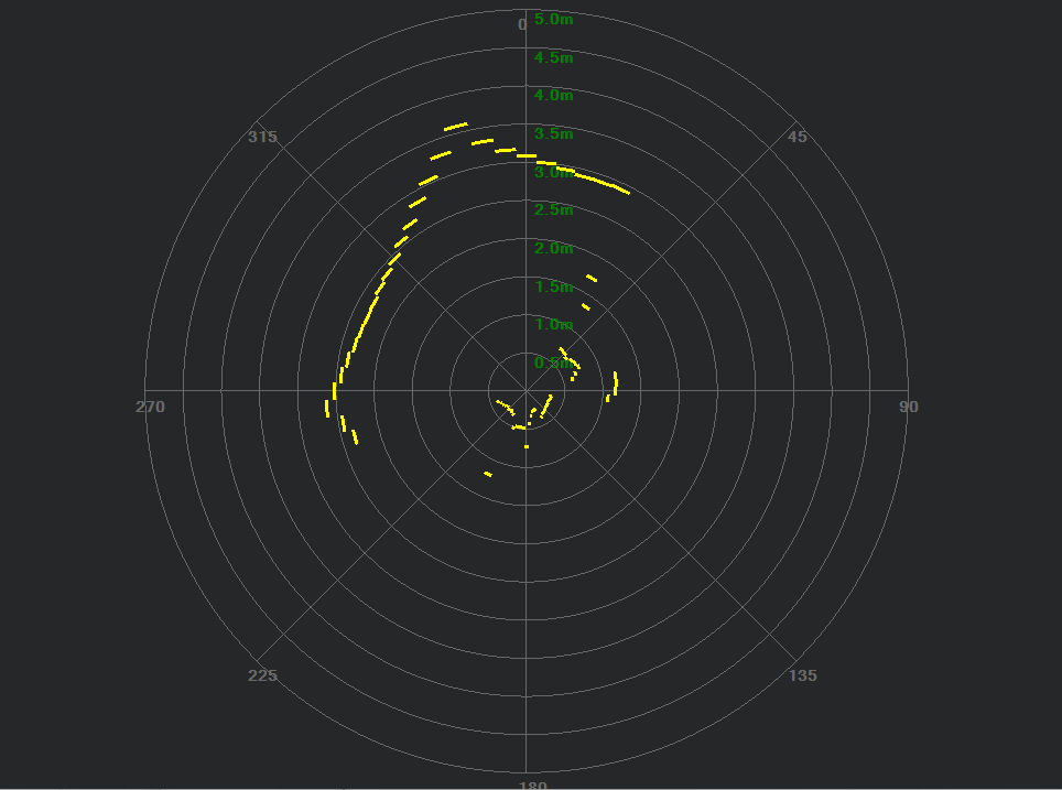
since it’s going to be in a public place I need to add some proximity avoidance so I don’t hit anything or anyone so I got one of these LD06 Lidars, they were very cheap, I got it for £20 off eBay. but they have some issues. the main one was that it’s not a laser dot that comes off it like some lidars but it’s more of a detection cone that aims up. so if you mount it inverted all you get is a circle where it’s picking up the ground. I have converted it to mavlink using an RP2040 and then sent it to the flight controller, I think it’s natively supported now.

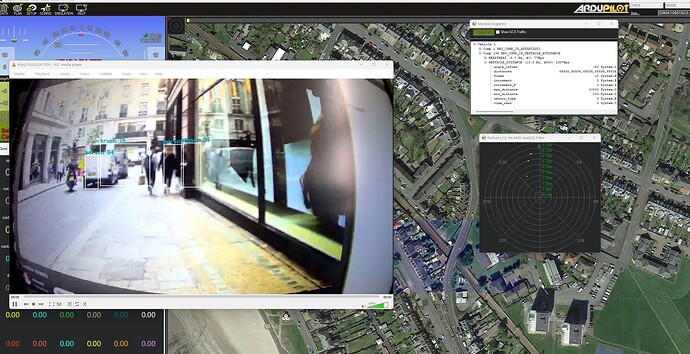
since this is all eventually going on a boat I needed something more than a lidar since it’s not going to work well on water. so I have an AMB-82 mini AI camera system with an FMK24 radar connected to it. so I can use the camera to identify what’s detected then use pixel position to give me an angle relative to the vehicle and use the radar to give it a range. the AMB82 has a built-in NPU so it doesn’t need a companion computer but it’s very low-powered so it only gets around 5fps at 640x480. thats more than enough for my rover thats going to be running less than 1m/s. my logic is the closer the object is to the bottom of the image the closer it is to the vehicle so I’m sorting the objects by the lower box position and then using that to assign radar returns to the objects but it’s not ideal and prone to errors when there are multiple objects or the vehicle is rolling so I need to work on that more. I am eventually going to do some slightly different actions based on what is detected. so on the rover, if it detects a person or animal it will immediately stop just to be safe.

there is a second esp32c3 mini onboard with extra sensors, for environmental sensors, it has temperature, pressure, and humidity, for security when it is stationary and charging it has 3x directional human presence radars, a vibration sensor, and audio level sensor that will flash the hazard lights and sound the car horn and I get alerts to my phone if anything is triggered.

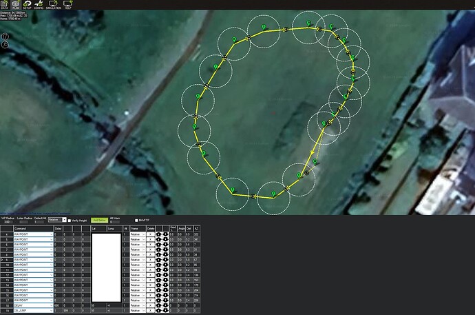
The rover has been doing laps around the park, it will do a lap, then stop at the top of the hill for 10 minutes or until the batter is charged above the minimum and then it will restart. if it survives for a few days then i will going to take it to the beach to do laps.

I have added a geofence around the area that im driving so it should stop if it goes too far.

my next step is to get the power consumption down when sleeping, 10w is still a lot especially when it starts to get dark in winter. to get it through the winter I will need to get the power consumption under 1 watt. I have ordered a pizero2 to run Drone Engage, which should let me replace the Android phones running Andruav to save power as it’s much simpler to shut down and restart a pi than a phone. since the Pi doesn’t have a modem I have ordered a ZTE 4g Wifi hotspot that has a pair of external antennas, this should give a better signal than the phone and it can be on without the Pi so I can shut down the video and still have telemetry.

The esp32 has an 8mhz ultra-low power core that I want to take advantage of if the power gets too low so it can still be running to monitor essential sensors and wake the main controller with an interrupt if a value or pin is triggered. it can’t do wifi without the main cores but it wakes them up for that. it should bring the power consumption of the esp32 from 0,33W down to 0.0033W when just monitoring for GPIO changes.

I found a lot of useful information here about how to run ardupilot without intervention. I am just planning to send my boat around the islands of Scotland where I should have mobile coverage so I shouldnt need a satellite connection.

there is still a lot to do so I will update with more progress.
8 Likes

That is excellent !

Miss some eyes for a Wall-E style !

1 Like

Very interesting project. I’m curious of its end goal as a boat.

1 Like

Very cool project.
As I understood, you need always a steady (24/7) link (by phone) to the rover. Is this true? Why?

It doesn’t need a steady link to run but I want to log all the sensor data at all times to my server and keep an eye on it so it doesn’t get stolen or vandalized by sending alerts to my phone if anything is out of the ordinary like it starts to move or the vibration sensor is triggered or the radars detect movement around it when it should be stationary and charging.

When its moving I want to get alerts from the AI camera with what it’s seeing and how far away it is, so I get alerts for people or animals close to it, also alerts for things like pitch or roll out of tolerance or if it’s started raining.

I can log into the orange wifi camera and see what’s happening, the camera has an intercom system built into it so I can speak to people. there is also a Text to voice function that I can use to send messages.

I think this should be changed to a Blog post :slight_smile: Nice work.

3 Likes

@amilcarlucas if you want to move it to blogs that’s fine, I didn’t think it was good enough for that, as its still a work in progress.

nothing prevent you to make a blog to show the state now, that is already quite details and intersting. And makes another one showing the full system integrated !

What people are looking for on blog is example and showcase of what can be done !

1 Like

I was going to leave the blog post for more of a “how to” post where this is just documenting progress.

If you like, @geofrancis, we can brainstorm a little how to reduce your power consumption as best as possible.
Which device is keeping an eye on the sensor data and send alert to your phone? Is it the onboard controller (ESP) on our rover or it is your (intelligent) server?

I already have a plan for getting the power consumption down, at the moment the 10w idle consumption is caused by using mobile phones for internet connectivity. they are great for short-duration use like in my urban rovers but due to Android security there are restrictions like you have to have the screen on if your using the camera, and I can’t just turn them off and on remotely. to get around that im moving to a rasperry pi zero2 that is much easier to manage since I can just switch it off and on but because it doesn’t have a modem I will have to add a 4g wifi hotspot. if I want to drop the last 3w, then I could put the esp32 to sleep along with the 4g modem for a timeout or until something like a radar or vibration sensor is interrupted. in that mode, it would run for weeks just from the backup battery alone. it could still do some basic tasks using its ultra low power core without waking it up but its complicated to get set up.

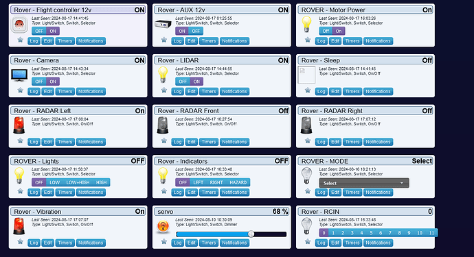
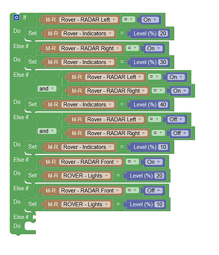
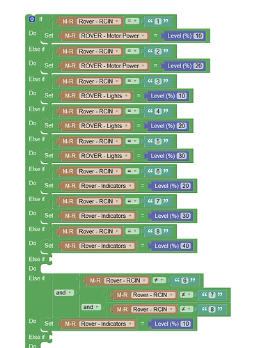
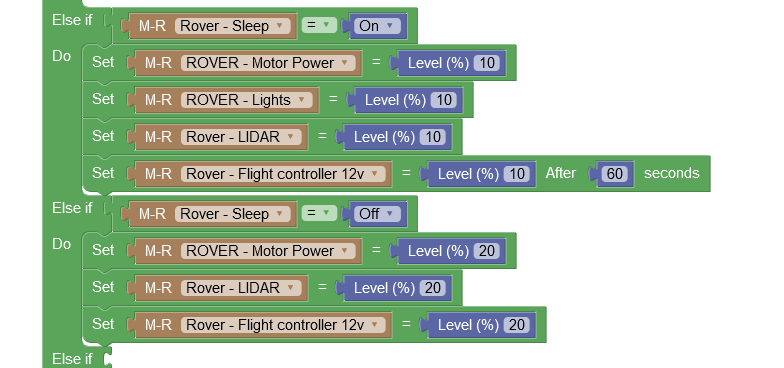
domoticz automation system is what is monitoring my rover, im using it to log sensor information as its much better for using over months compared to something like mission planner. it also lets me set up basic tasks using blockly rather than having to code every little action. its designed for home automation so some of the terminology is a little off like you have to use thermostat set points for all your set points and switch positions are set as % but it works.


don’t forget to reboot ardupilot something like every 4d to prevent overflow on variables !

2 Likes

is this documented anywhere? it would explain a lot.

I don’t think so, but the millisXX() call are limited to 32bit so that limit the time you could count. There should be some other variable that overflow. I think the break happens after 5-6Days. It should be verifiable on SITL by forcing the speedup to 50 or something fast.

But yes every software will finished by overflow at some point, just a matter how to handle it and AP is not yet done for weeks activity (or maybe with the linux version ?)

2 Likes

It’s a pretty easy script to reboot prior to millis overflow. Could be refined to look for a non-moving condition or even set at a certain inactive time of day.

Great project!!!

1 Like

I have been seeing all sorts of crazy issues when its been left on for long enough most of the time its unresponsive but i have seen the hud doing backflips., some googling shows im not the only person to have ran into these issues

https://rsaxvc.net/blog/2024/2/4/ArduPilot_A_Matter_of_Time.html

RC test flight did a lot of good videos a few years ago on a solar rover, almost all of his failures were due to mechanical failures in the gears for his drive motors with hoverboard motors lacking gears I should avoid those issues. One of the main reasons I went for 6wd was that I had seen his getting stuck in the mud due to a lack of traction. and the wide square 3d printed tyres are much better on soft ground than rounded tyres that tend to dig rather than roll.

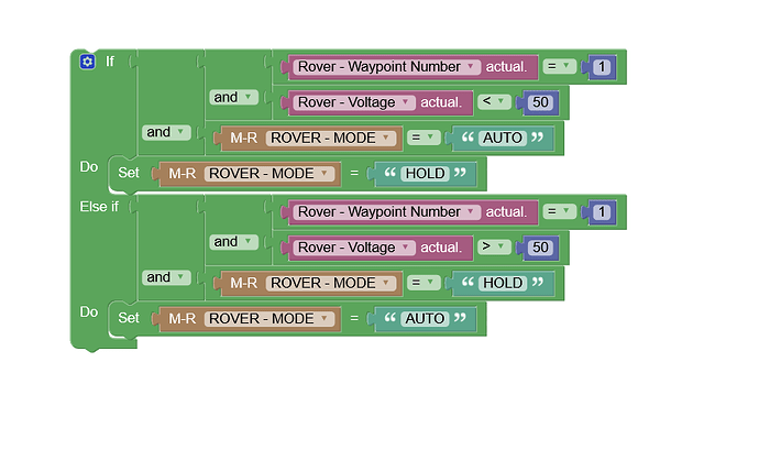
he used an Arduino to change an rc channel to change the mode between auto and hold based on the voltage, I’m using the esp32 to change the modes since I wanted my rover to stop at a specific waypoint to charge rather than just wherever the voltage got low and to do that I needed to get data from the flight controller.

he had a lot of navigation issues, my guess would be mounting the compass between the solar panels probably sent it off-course, my compass is around 80cm above the panels so it shouldn’t get interference but I have an RTK GPS with YAW that I could use if I have problems and a geofence that should stop it wandering too far off course.

so much for my ideas of hoverboard motors can’t fail, I managed around 2 laps of the park before a wheel jammed, so I had to trailer it back home and clean it before I could take it back inside. Upon cleaning i saw that a bolt that holds the wheel together had come out and got stuck on the frame, not ideal but it’s a minor issue that I wish i had seen at the park but with all the grass and mud I missed it. it probably got shaken loose when driving it to the park, the hard plastic wheels cause the rover to shake a lot on hard sufaces.

It took me a while to figure out what had happened because everything looked fine when I was looking at mission planner and the cameras but it just wasn’t moving. because of the way the solar panel is mounted, it causes a lot more weight to be carried by the rear wheels, so when one of them jams the others can’t drag it and it ends up trying to dig a trench. im going to add a warning to the motor controller so that if a wheel is reading zero RPM when it should be turning it sends out a mavlink message warning. in hindsight, if I looked at the hoverboard telemetry I would have seen the RPM was different. adding a message should make it harder to miss.

I have implemented some fixes, it now looks at the average speed of all 3 wheels on one side of the rover, because im running them in speed mode they should all be identical, so I have set it to alert if any motor is less than 10% under the average. I might expand that to shut down but I will need to do some testing with just alerts first. If any motor controller gets above 70C I will get an alert and if any hit 85C it will shut them all down.

I had another issue where I took it out and some network issues caused me not to be able to log into it to be able to turn it on so I’m going to add some physical override switches that will let me manually power up the motors and flight controller so it can drive using regular RC without network access.

The power systems are getting some changes to try and make them more efficient. at the moment there is a main 48v>12v 10A step down that powers everything like the lights and flight controller, it’s then stepped down again to 5v to run the rest of the electronics. so to lower its idle consumption I added a 48v>5v stepdown just for powering the modem and esp32 via the 5V UPS, that way don’t have to go from 48>12>5v so should be a bit more efficient when sleeping.

2 esp32 boards are running, one is the main management controller with the relays and one is a c3 mini with external sensors like radars and humidity, so I have added a routine that will put the main esp32 into deep sleep if specific conditions are met, so it has to have the flight controller and motors off and the voltage has to be getting low. The main controller will sleep for between a minute and 20 minutes depending on how low the voltage is and the C3 will sleep every minute if nothing has been detected on any sensors.

The idle power consumption with the LTE hotspot enabled and everything asleep is around 2 watts but I can get that under 900mw if I use something to switch off power to the sensors connected to the C3. I’m going to add a small transistor to switch them when the controller is sleeping.

If I used a different modem that I could switch off and on then I could drop the consumption down to 120mw, thats around 4 days on a single 18650.

I might add a gpio expander to the main esp32 for driving the relays and freeing up pins, then I could get rid of the second esp32 and use the sensors to wake the esp32 when a sensor is triggered rather than waking on a timer.

I’m looking at making a small wind turbine, I could make a fixed one out of a brushless motor and a propeller since It only has to make a watt to keep the rover running. I have had a few aircraft power up while being carried when the wind starts spinning the propellers so it should work, I have some low kv motors I can test.

I need to replace the LD06 lidar, it’s useless outdoors. The cheap vacuum cleaner lidar worked better, it would only get some noise if direct sun shone into the lens but the LD06 just has noise in every direction even when it’s overcast. So I’m looking for a cheap 360 outdoor lidar.

1 Like

Progress:

I have ordered a MCP23017 i2c GPIO chip, they give you 16 GPIO that can be used for input or output, I use them a lot for driving relays as they are resistant to the main controller glitching or toggling pins on startup. It would be nice to see these supported natively with Ardupilot, it could probably be done with lua it would make starting up safer since most flight controllers toggle pins on startup so ideal if you have large spinning machinery attached. This will let me move most of the basic IO off the esp32 pins so they can be used for sensors that have more than a basic binary output.
image

using this as a guide I have updated its sleep routine,

Now it will go to sleep to save power and still wake on a timer but now I have programmed it to also wake when any of the 3 RTC pins I have set go high. im going to connect the radars to those pins so it will wake immediately if anything gets close to it when it sleeping.

When looking at what kind of warnings or alerts i could put on the rover, it has a beeper and a car horn I can use depending on the situation but they arent really clear on what they are signaling. so i went looking for some kind of text to speach system and found this:

this lets you generate words using the esp32 DAC, (it also runs on 8bit controllers) it uses ROM dumps from old 1980s voice generators to say pre-generated words. there are a few hundred words mostly related to computing and aviation so it could be used for basic telemetry calls but on this I’m looking at just using it for warnings. something like “warning motor start move immediately” and calling out waypoint numbers"way point one". It can do custom sounds so an Ardupilot-specific one could be made but thats beyond the scope of this.

if you got a 3d printer, try helicoidal turbine, you should gain some space for the same production :
something like : Tornado: New Portable Savonius Wind Turbine | Indiegogo

1 Like