I have been looking at turbines the problem I have is I can’t find any test data on any of the microturbines, like that one you link to, they just state what the battery built into the base can do but not the actual turbine itself.
production is quite low but it can produce something if you are at a windy area. Should be enough for 1arduino or esp not at full power
1 Like
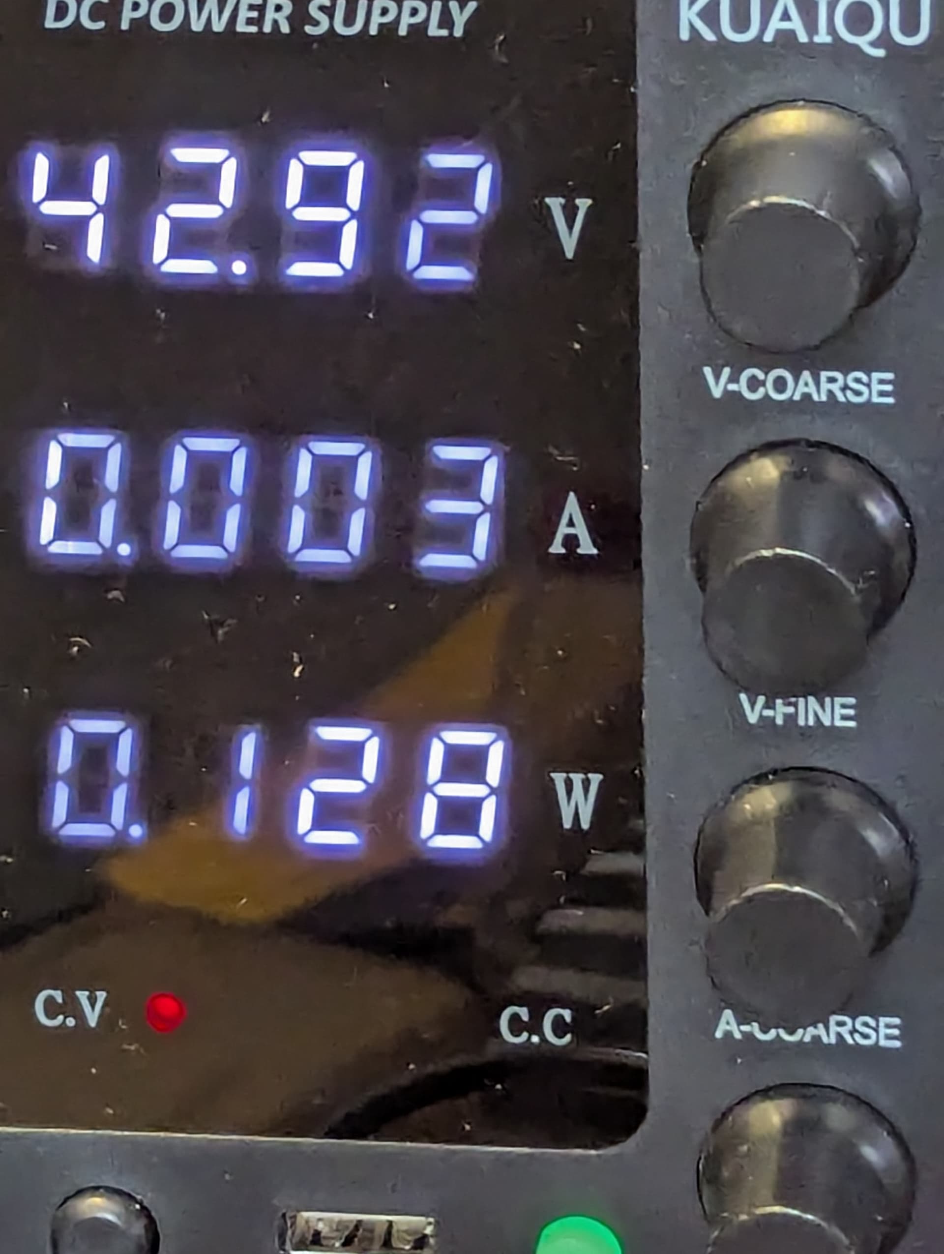
if I remove the second esp32 and change it to a modem that I can switch off I can get it down to 128mw when it’s asleep,most of that is probably the leds on the esp32 and UPS , at that point a hamster wheel could keep it alive but I would still like it to be able to do at least 1 lap every day. I’m right on the Atlantic Ocean so the wind never stops thats why I think I can get away with a very small turbine to get it through the darkest winter days, when it’s at the winter equinox and it rains all day my 1400w of solar panels connected to the house will struggle to make more than 20W for just a couple of hours that would translate into the 200w on the rover struggling to make 3w for a couple of hours. there is very little sunlight in the winter here sunrise is 8:30am and sunset is 4:30pm and it only just comes above the horizon.
The rover will use around 50W when it’s moving and it will take around 3 minutes to do a lap of the park that works out to 3.5wh a lap, say 5Wh to be sure. so it shouldn’t take much to get it to do a lap at least once a day. even generating only 1W is enough if I can do it over 24 hours. I’m probably going to have to look at a heater and insulation for the battery, letting it go subzero and then trying to charge it won’t be good for it. The BMS has thermal limits on it so it won’t charge if the temperature is too low. I have a version of my motor controller code that connects to the BMS for cell voltages so I should be able to get the temperature data from the 2 internal probes and use that to thermally control the battery via the heater relay.
since it’s connected through my automation system that gets weather updates I have been thinking about whether there is a way of using the weather forecast to manage the battery. so if the weather forecast is to be bad then it can conserve power in advance so it can do a lap every day rather than burning through its power and having to stop for days when the weather gets bad.
I could also skip laps if the wind is too high to limit the possibility of damage to the solar panel.
It won’t be generating much power when it’s raining so I will probably skip laps until it stops.
I have sunrise and sunset triggers so I can set it to stop several hours before sunset to make sure its got time to charge before it gets dark.
A heated autopilot like the Cube Orange would be beneficial here. Also recommend running the following tuning if your autopilot supports it: IMU Temperature Calibration — Copter documentation
don’t be so humble. Lots of people including myself are considering something similar. Quick question, do you have any problems with the suspension of the vehicle, I.e the wheels don’t contact the ground on uneven terrain?
its designed for sand and flat grass it can’t go over anything very big at all, its only got around 4cm of ground clearance it gets stuck even on a small kerb its just some hoverboads with different tyres.
Excellent project! I am considering something similar but based on a stripped down golf cart that would live exposed on the property and be able to roam as needed.
Great write up also!! Onward!
1 Like
I might be wrong about this LD06 Lidar, I was just looking through the code again and I don’t think I have the filter set high enough so it was getting lots of false returns when the sun hit it. so im going to increase the filter to see if that helps outdoors.
I was going to remove the second esp32 C3 but I have decided I’m going to keep that for the weather sensors and just move the radars to the main ESP32, since I don’t need to wake to check the radars now as I’m connecting them to the main esp32 with RTC wake pins I can just switch off the second esp32 and turn it on every hour to send some weather information. I still have the wind sensors from my old boat so I’m going to add them to the temperature and humidity sensor and rain sensor to make a basic weather station just so it can do something useful when it’s not moving.
I’m currently working on getting drone engage working on a pi, because I can fully switch it off it will save a lot of power compared to running an android phone that I cant switch off and on remotely. I have designed a servo gimbal thats controlled by ardupilot.
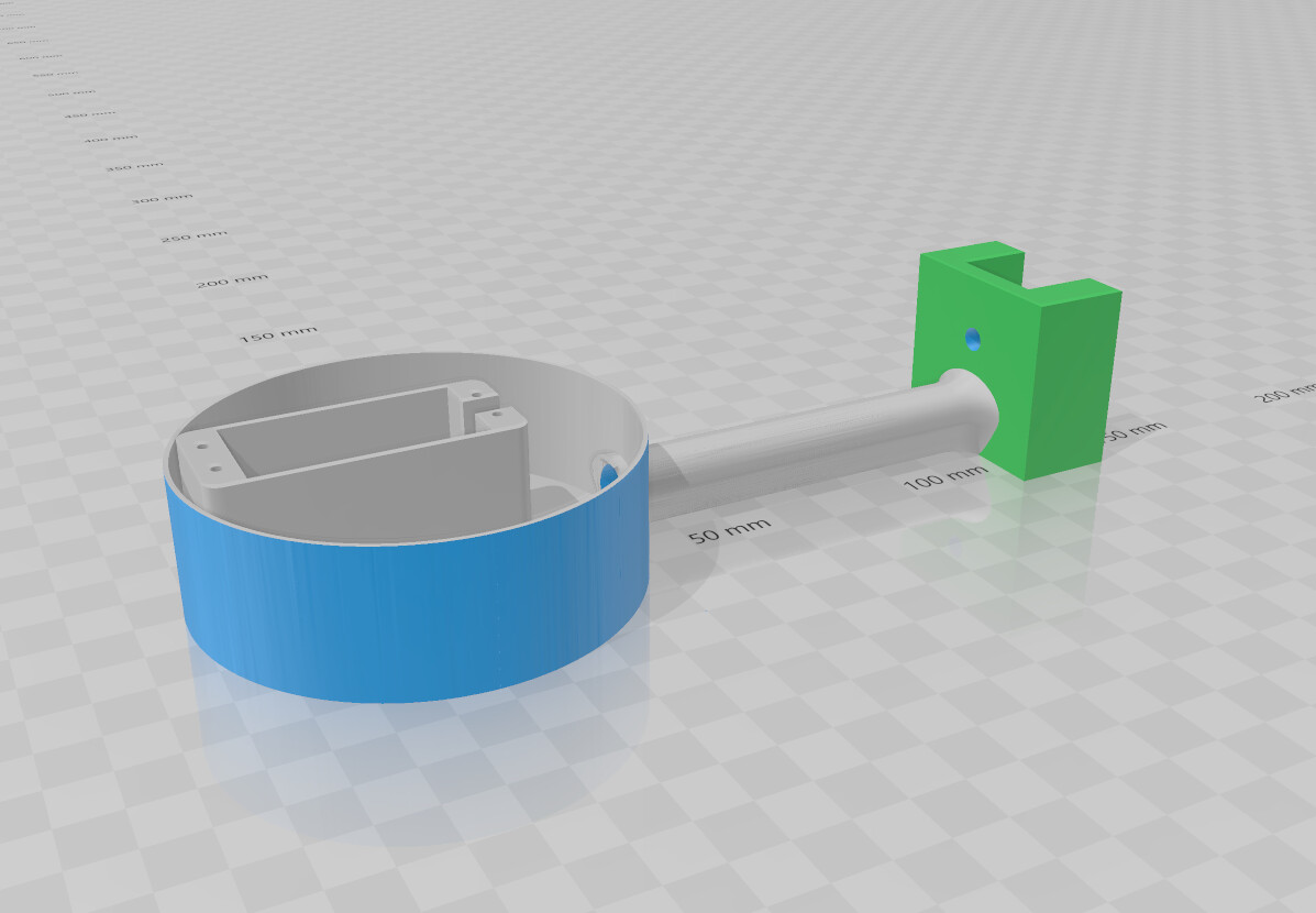
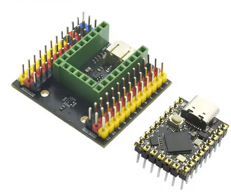
its based on these 2 parts.
I’m still trying to get good depth information from the AI camera, using the radar works but it has a lot of issues. the main one is what to do with data that doesn’t match, so what do I do with an object that doesn’t have a corresponding radar return or radar returns with no object detected? I have tried using the lower box pixel position to give a rough estimate of distance but it doesn’t work well with multiple objects or uneven terrain. my next plan is to get 2 cameras and try and do some trigonometry using the pixel positions to get stereo depth. my understanding is that if I can get an angle from each camera and I know the distance between the cameras I can calculate the range.
I have been trying to reduce the power consumption further, I am changing out the esp32 relay board for an esp32 board designed for low power sleep. This should take it from around 130mw with the omni radar to around 8mw. Essentially nothing on a 960Wh battery.
I have found some 5v latching relays that I can use for switching essential components like i2c sensors and the 4G modem, that way im not wasting power holding a relay closed all the time, this only takes a small pulse to change it to open or closed then it stays there.
https://www.aliexpress.com/item/1005006982276091.html
I have fitted a little omni radar to wake it up if anything is around it as well as the esp32 timer, it only uses 7mw so effectively nothing. it gets a lot of false triggers if there is moving vegetation or water around but its only to wake the rover that will be perfectly still in the middle of a park, when it wakes it will upload data from all the sensors then go back to sleep. The boat will use the timer and a vibration sensor since it’s always going to be moving.
https://www.aliexpress.com/item/1005002790170585.html
in order to monitor solar charging and the battery discharge closer, I have installed some Matek I2c INA228 power sensors and connected them to the esp32 so it can monitor charging current from the solar panels and discharge from the battery.
https://www.mateksys.com/?portfolio=i2c-ina-bm
I have used a Matek L431 canbus node to convert the Here+ M8p GPS to canbus, it simplifies the wiring and i can add another GPS and compass without more wires.
All the GPIO has been moved to the i2c MCP23X17 GPIO expander to free up pins on the esp32.
Arduino OTA updates have made flashing much simpler, I just pick the esp32 on Arduino ide and flash it without having to wire it to the PC.
I added telnet server, so I can connect and see terminal output without having to attach a wire, its an issue as I’m using the main serial port for the flight controller so being able still use terminal without tying up a serial port is very useful.
As well as the wind speed and direction sensor, I have added:
BH1705 i2c light sensor to verify the light level vs solar panel output and try and catch lightning strikes.
AS3935 i2c Lightning sensor gives the strength and estimated range of lightning.
i2c BME680 barometric/temperature/ humidity sensor.
ADS1115 4 channel i2c ADC with an Analogue Audio level sensor to hear thunder and a rain sensor connected.
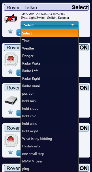
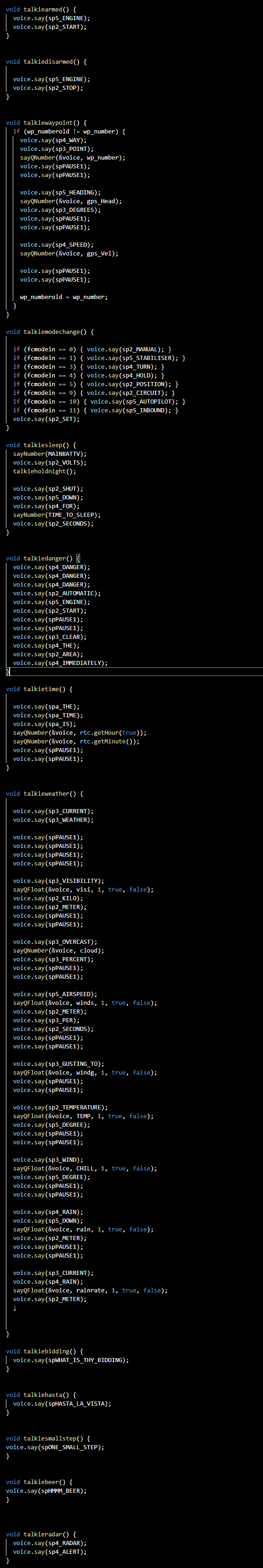
The talkie text to speech has been expanded so it can speak out waypoints, warnings, the weather, how long its been on for and why its in hold mode like light too low, wind too high, battery too low etc, a warning if its about to move, the idea is if anyone walks up to it the radar will detect them and it will read out all its information, IL probably put a QR code on it linking to this thread in case anyone gets curious.
I dug out this AIS receiver I bought years ago, the problem I had was that it would output NMEA GPS and AIS messages over the same serial link and there wasnt a good way of handling that with ardupilot since ardupilot expects the AIS and GPS to be on their own serial ports. So it was going to take 2 serial ports to use both the GPS and AIS. So to get around that I have split its output so one goes to the flight controller so it can read the AIS data directly, the other goes to the ESP32 where its parsed and the GPS messages are read and converted to MAVLINK before being sent over the telemetry link back to the flight controller so it can be used as a secondary GPS along with calculated YAW based on GPS track.
https://www.aliexpress.com/item/1005005636600614.html
Since I now have the GPS data into the ESP32, its then parsed by TinyGPS++ to give heading and navigation information, I’m going to use this as a backup/low power navigation system, the idea is for it to read the current waypoint from the flight controller via mavlink and run in parallel so it can compare how its doing with how it thinks it should be doing and if the heading information starts to disagree then it can take some kind of action like warn or take over or hold or if power gets really low it can power down everything other than the esp32 and the GPS and still navigate, if it gets even lower it can be placed into deep sleep and woken with a timer. The heading deviation detected when it wakes could be used to set the sleep time, so if it wakes and the heading has barely changed then it could sleep for longer whereas if it has changed a lot it will only sleep for a short time to reduce the time error can build up.
I am using some code I found to calculate the suns position, I’m going to try and use it to work out where the sun should be then measure where it is relative to the vehicle to work out if the vehicle heading lines up with where the sun should be as a way of verifying the vehicle heading. By just using a servo gimbal thats calibrated I should be able to just look for the sun and use the gimbals angle to check the angle to the vehicle and see if that lines up with where it should be at that time with the vehicle at that place, i don’t think it’s going to be practical, but it might work for verifying a compass is working.
I am trying to get the es32 to scrape data from the internet directly that it can use. The main one im trying to get working is Tide times, I have an RSS feed that I can get the data from but I haven’t figured out how to parse the data correctly, I can get about half of it, basically it stops at the first set of numbers and I can’t get the rest, it’s been problematic, unfortunately there isn’t much information on reading RSS feeds with a ESP32.
Now the problem im having is doing all of this is really slowing down the ESP32, so im struggling to keep the GPS updated at 5hz so im working on using the second core for it but its not very simple. There are a lot of restrictions on what you can do once you use both cores, so far it keeps crashing, so i need to look into it more. im also running things far more often than I need to at the moment while testing, once it’s out i dont need it checking the server every 2 seconds.
Since I’m installing drone engage on a raspberry pi, I have been looking at what else i could do with a pi onboard, and it does open up a lot of possibilities but its a steep learning curve as its all in python that I have never used, so I might get more into that next year.
1 Like
some progress,
Drone engage is now working properly, basically the problem was with the pi serial port, on a pizero2 there is a hardware serial port and a software serial port, by default the hardware serial is internally connected to the bluetooth and the serial pins to the software port, this should have still worked but by disabling the bluetooth, it connects the serial pins to the hardware serial port and it started working using serial port AMA0
I can now get RTCM corrections over the internet using a esp32 to fetch the data from RTK2GO, this way I dont have to have mission planner running at all times to get RTK.
I have moved all the environmental sensors (wind direction, speed, temperature, pressure, humidity, rainfall, lightning, lux, audio level) onto a separate esp32c3 board, i couldn’t get the esp32 to run without lagging or crashing when I tried to use 2 cores, so I just moved the sensors back onto the separate controller.
I have made a basic wind turbine using a 300kv brushless motor and a pair of 12 inch slow fly propellers, I was able to get 100mw using a small desk fan to turn it so it should be enough to keep it alive in sleep mode with a decent wind.
I have added 7 RGB leds around the LIDAR mount so they change colour based on how close something is.
I have installed a pair of Matek I2c INA228 sensors, one for the main battery and one for the solar panels they are extremely accurate compared to analogue sensors. I also installed a pair of INA218 sensors for the backup batteries to monitor their levels.
I made an updated version of my mavlink serial multiplexer so it now gives out a serial bridge heartbeat. basically it works by taking advantage of the routing between the ports on the flight controller, one port is set at 115200 and one is set for 1500000, all the device RX pins are connected to port 1 TX pin at 115200, then all the device TX pins connect to the RP-2040 serial ports at 115200, the data is then forwarded to the flight controller from the RP-2040 over port 2 at 1500000, the reason for the 2 ports is that trying to fit everything down a single 115200 port causes problems once you start sending too much data, using a second port at a much higher speed gets around that issue but if your only using low speed devices then you could use a single port.
1 Like
I have redesigned my mavlink serial splitter, so now it only needs one seral port to run 5 mavlink sensors. it now relays the mavlink data out of one of the serial ports on the rp2040 that is then shared with all the other devices. The sensors still cannot see each messages from other sensors as there is no routing happening, this is fine for most sensors and I still use the flight controller serial ports for telemetry like UHF and LTE or sensors that need a dedicated port. most of the sensors im using is for things like the motor temperature, battery levels, rangefinders or proximity sensors that dont require bandwidth or need to communicate with each other.

I have a verson of it that will route but its very slow if you route to all ports
I have redesigned the power system, so instead of 2x 5v backups there is a 12v ups and a 5v UPS, the idea is that everything is backed up by the 12v ups, with the 5v UPS only powering the esp32, modem and Wi-Fi camera.
1 Like
Due to a series of very minor but time-consuming issues related to the recent storms, I haven’t had a chance to do much but with the sun about to return im wanting to get this out for spring.
I have finished rewiring the power supplies, so now there is a 12v and 5v UPS so everything is now covered by one of the UPS.
there is now a 48v-12v regulator that supplies power for all the electronics along with a separate 48v-5v regulator thats running the UPS backup power supply system.
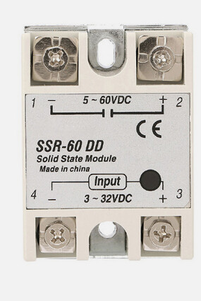
The latching relays I bought for controlling power to the main 12v regulator have been problematic as it keeps failing. I think it’s the high voltage DC that’s damaging them, so I have replaced it with a 60A 60v DC SSR that should be more reliable.
Its almost ready to go outside to live. all the wiring is done, i have done a full test of all the different systems so all that is left is to configure eveything for outdoors, thats basically going to consist of getting the 4g modem tested, reduce all the sensors update rates to every few minutes instead of every few seconds, sealing up all the different boxes on the rover and fitting big memory cards.
I have been trying to get some 802.11h halow networking equipment thats legal in the eu on 868mhz to link it back to my house to live stream it on youtube or twitch 24/7 without spending a fortune on data. it’s daylight from 4am to 9pm in the summer, so it should have enough power to keep a phone running.
I *ucked up, I managed to plug a connector in backwards, the wire I was using has 4 colours, red, brown, yellow and orange, due to low light I managed to mix up the red and brown (+ -) and took out a large chunk of the electronics on the vehicle when i reversed the 5v rail. I am very annoyed as it was basically complete and i was just tidying up the wiring so the esp32 relay board, rp-2040 serial router, 2x INA219 i2c power sensors, i2c oled screen, i2c MCP23017 gpio board and audio amplifier are all toast, luckily the flight controller survived as its on the 12v rail.
On the bright side, I figure it was as good a reason to rebuild it better.
I had spare INA219 sensors. RP-2040 and OLED screen.
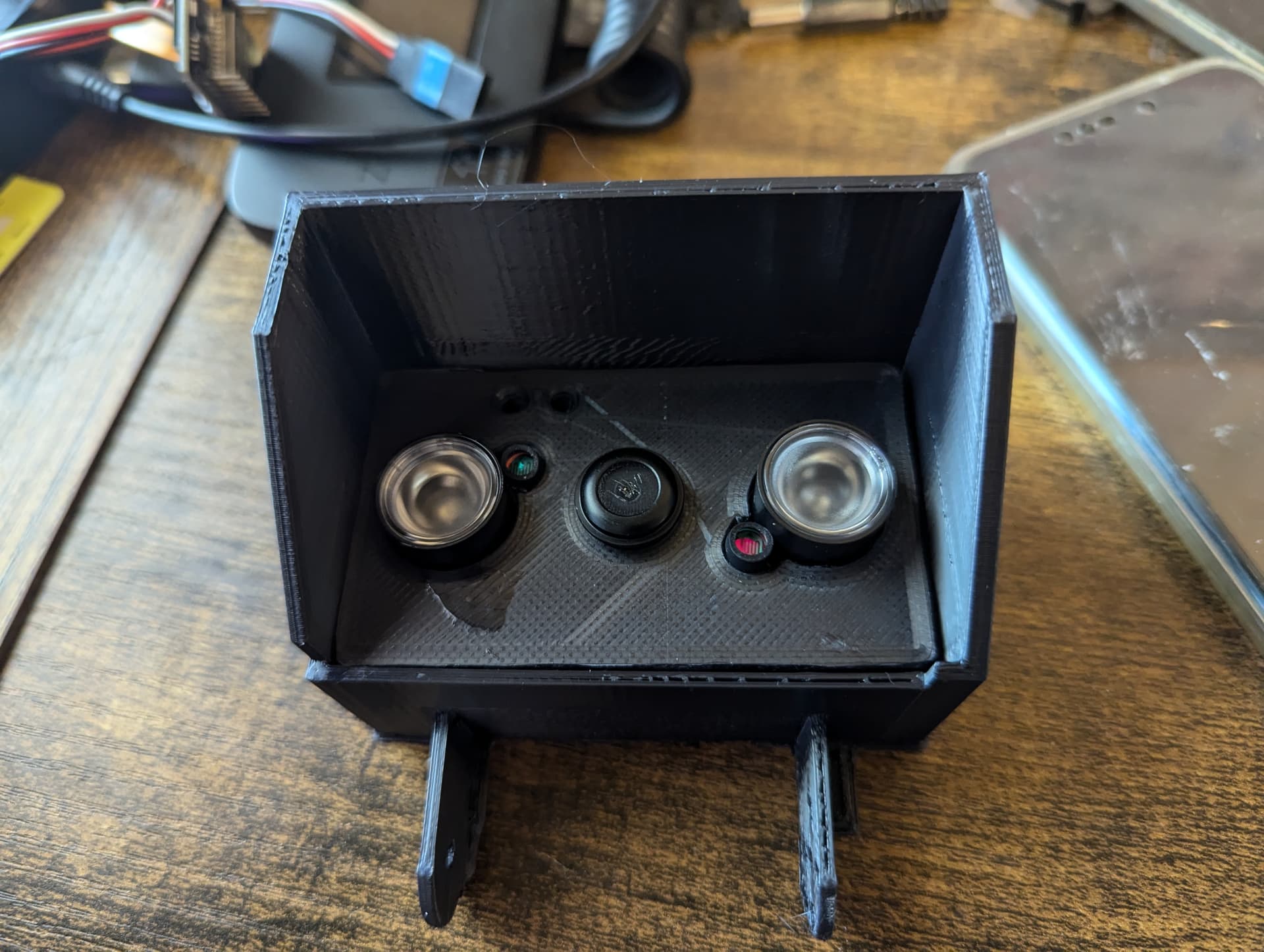
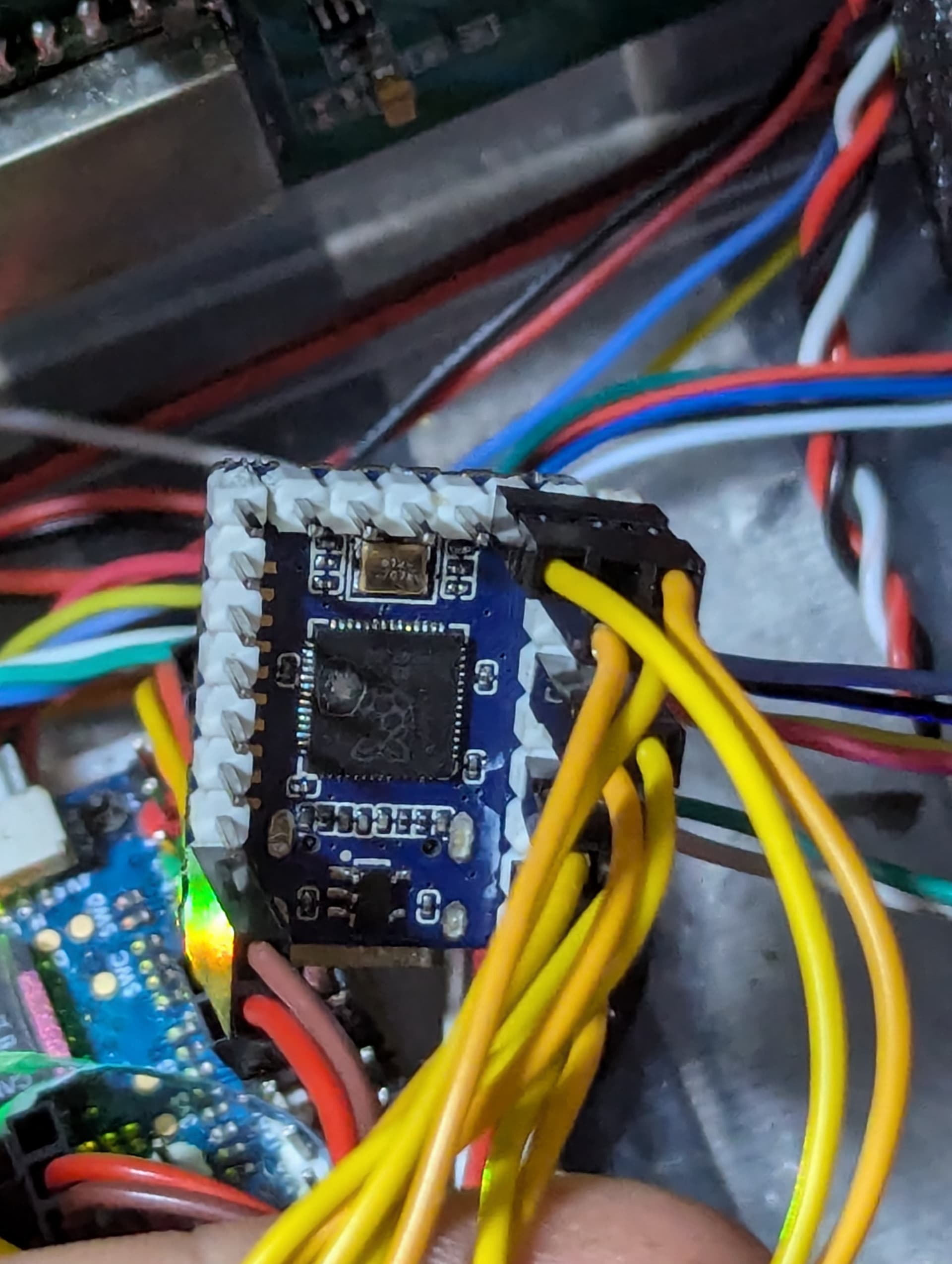
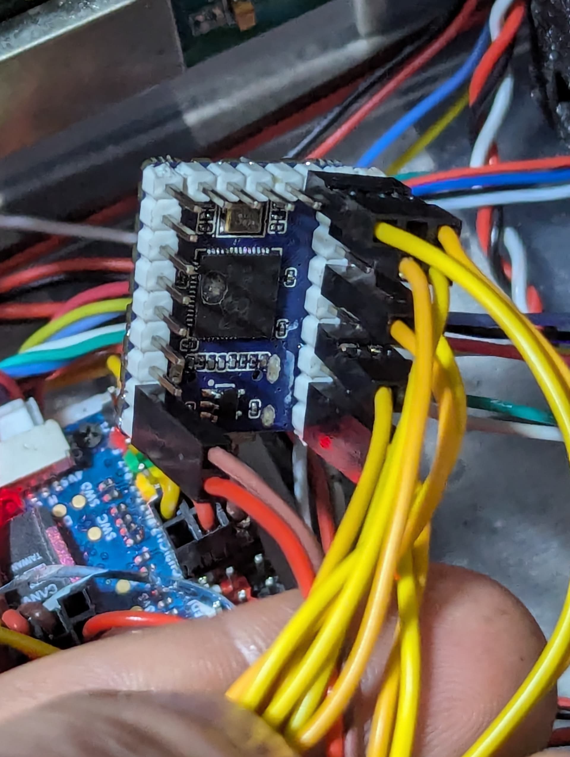
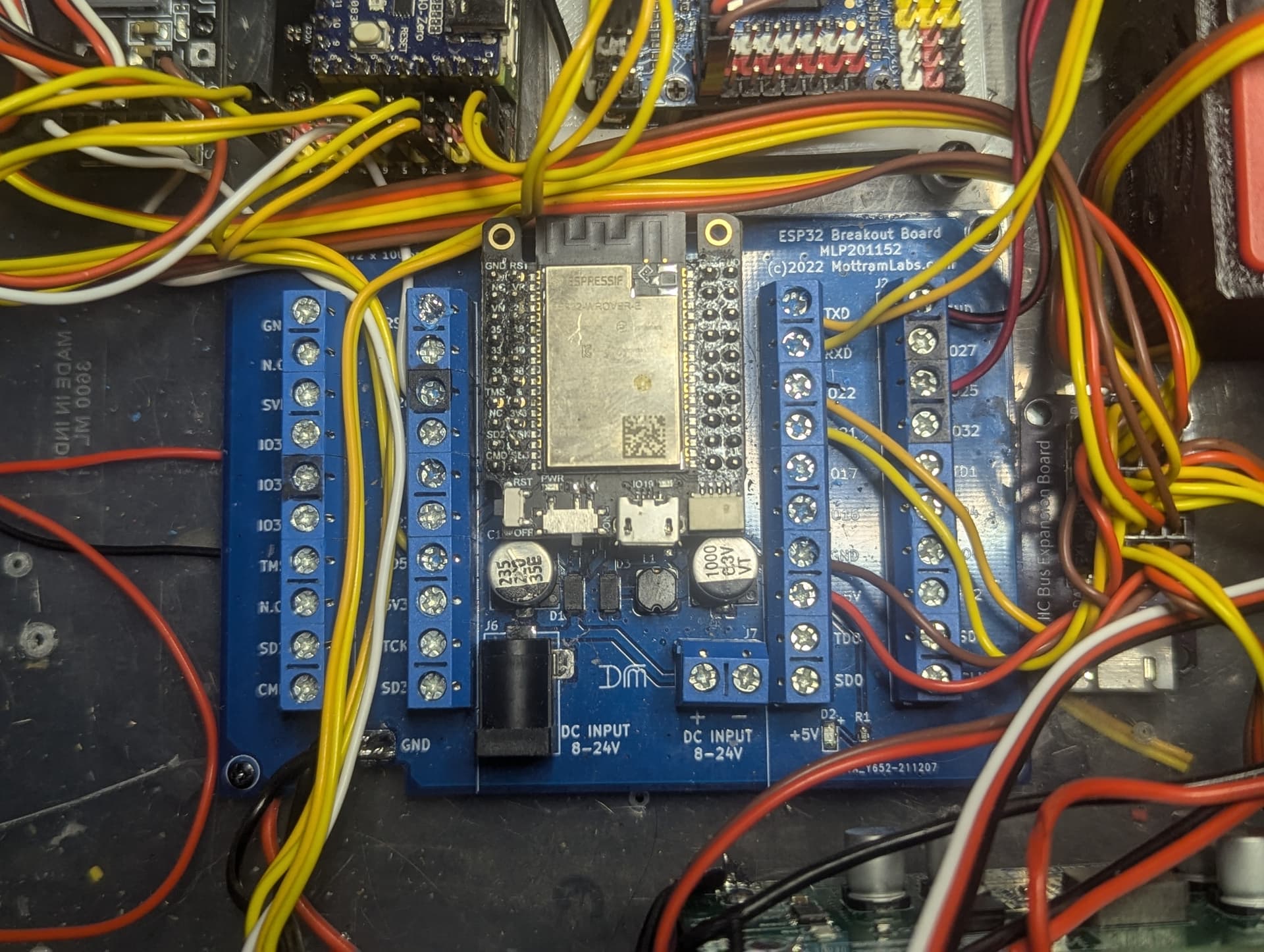
The esp32 relay board was a good idea but it soon became very limited as using all the GPIO for relays left few pins for other uses and I ended up having to modify it to be able to use pin25 that has the DAC so I have replaced it with this breakout board and mini esp32. it should allow for a fast replacement if something happens again and a lot more flexibility with pin selection. I also got a 16mbit esp32 board for it as I was getting close to the memory limit mostly due to talkie.
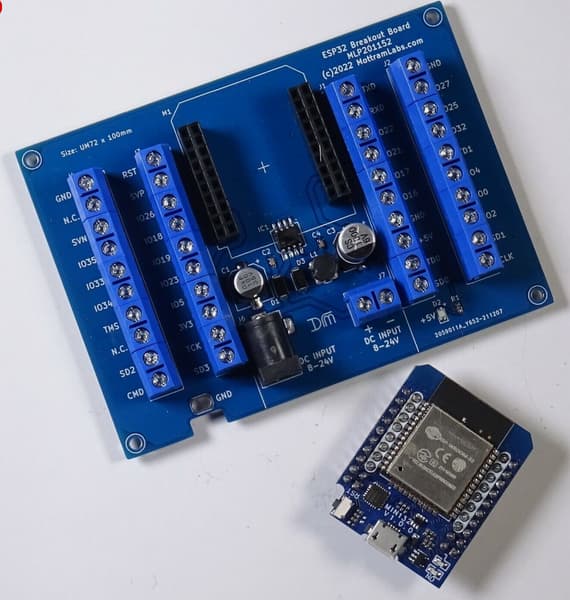
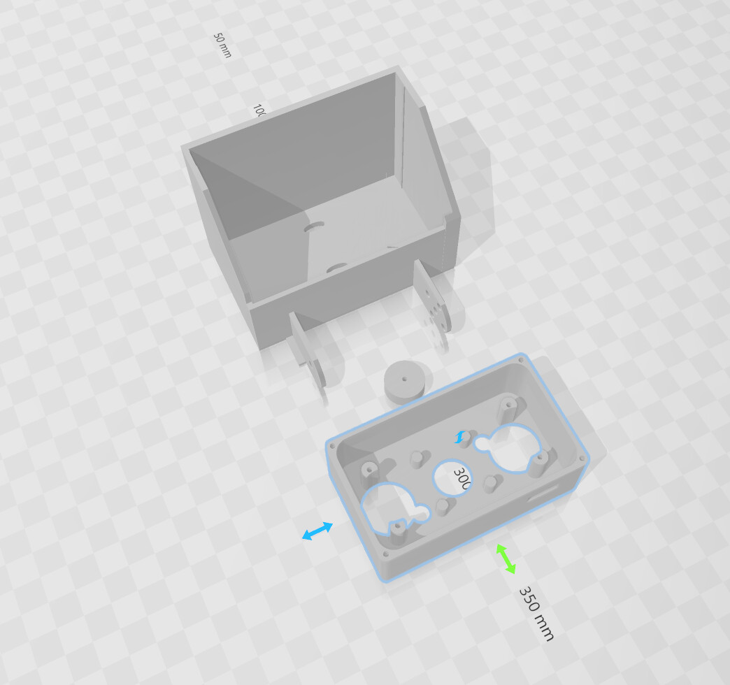
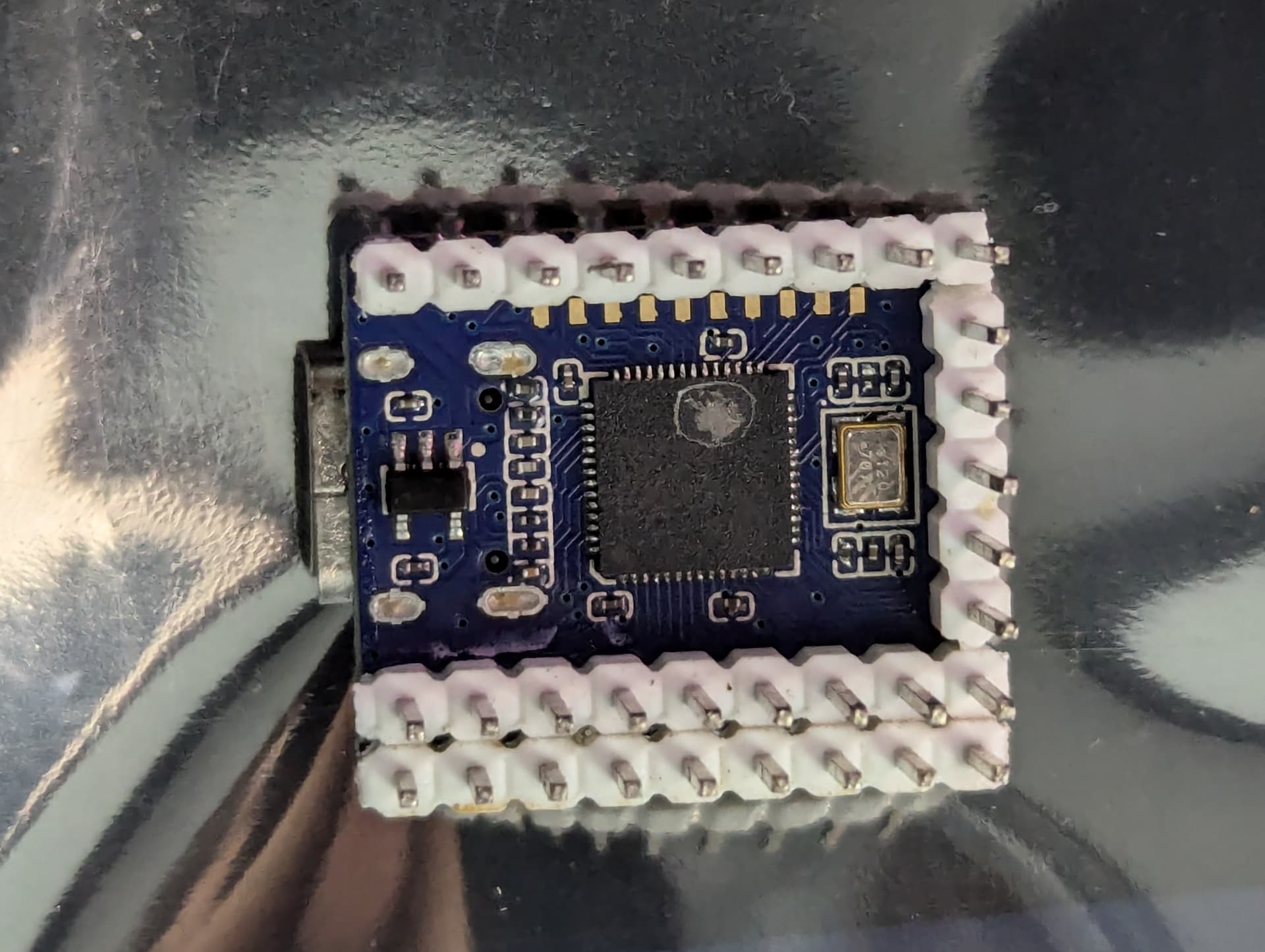
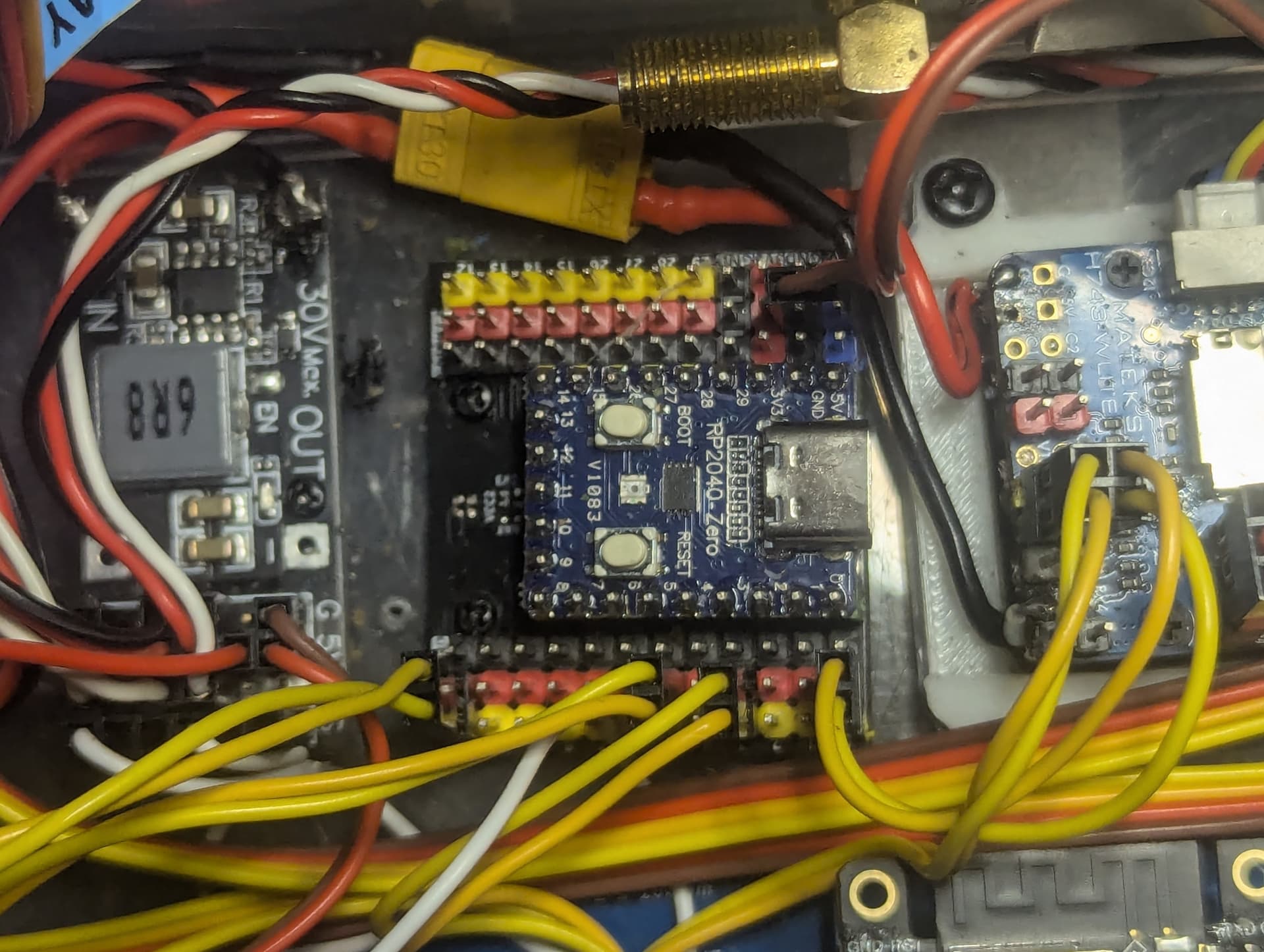
for the rp2040 mavlink splitter I have used one of these breakout boards. But to get it to work for mavlink I have removed the jumper for the 5v rail on one side so that is now the rail is the TX from the flight controller. Now I can just replace the controller without any custom soldering if it fails again.
I have got it all down to one serial port working reliably at high speeds, basically I was just running it all too slowly. With the link at 115200 there just wasn’t enough bandwidth for everything when it got busy so by changing all devices to 500,0000 and connecting them all directly to the flight controller TX pin it got rid of a lot of congestion so everything is now coming though reliably even with the lidar and radar and motor controllers running.
With ardupilot you can have 4x mavlink ports so I was using one for MLRS, one for DroneEnage and 2 for all the sensors but with this latest improvement now with the mavlink hub I only need a single port for it, that freed up a port that I could then dedicate to my esp32 companion. because it now has its own port it can receive telemetry from all the other mavlink devices routed via the flight controller. This now lets me do things like monitor the heartbeat of other mavlink devices and read things like the label name from the objects the AI camera has detected and send it back to my controller for logging or reading the lidar, or sending commands directly to the gimbal.
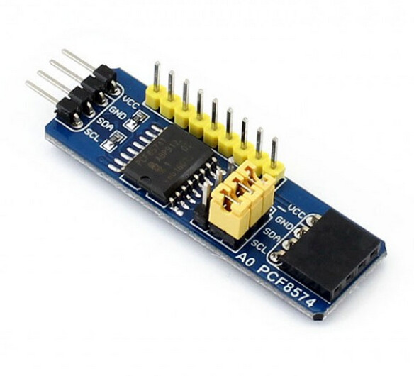
Since i got rid of the esp32 relay board I had to replace it with some more relays driven with a pair of PCF8574 i2c GPIO controllers, I tried to replace the mcp23017 but all the replacements I had were doa. so i had to pull some PCF boards off some old projects. It would be nice if these were supported with arduipilot directly for relays to free up gpio on smaller boards.
I updated the hoverboard control code it will now send a message to the flight controller if the motors on each side are not running in sync, like if a motor is stuck. it will also send messages if one of the motor controllers is overheating and will shut it down if it gets too hot, it will also shut off the motor controllers after a timeout with no mavlink data. there is also an override now that will let me turn the motors on using one of the relay outputs on the flight controller. so I can drive it with the remote without an internet connection as it wouldn’t do anything until it contacts the server for instructions and I had to trailer it back one time since it wouldn’t drive when there was an internet issue.
The AI+radar combo has had some minor software tweaks, now I have the mavlink routing working back to my controller it should become more useful as it will be able to take actions based on what it’s seeing. so if it detects a person or animal I can then do set speed to slow the vehicle down based on how close the radar is detecting it. I can also use the angle from the camera and the distance from the radar I can then send that to the flight controller as proximity information so it can use bendyruler to navigate around the obstruction. I will probably mount it on a servo gimbal at some point so it can track objects around it rather than just straight ahead. I have the code wrote for testing a stereo camera system or a dual radar system for more accurate positioning, but il see how this goes first.
my LD06 Lidar adapter has some minor improvements, I added the LUX filter so that should fix the issues i was having when it was getting blinded in the sun, I have added a RGB strip around the base so it gives a visual guide to the proximity. They start out green at 10 meters then change to blue then to red as it gets down to 1m.
DroneEngage has recently added text to speech, so i have ordered a usb sound device for the pi zero as its only onboard audio is HDMI. I am ordering a stereo amplifier so one channel will have talkie and one channel will be droneenage.
I have almost got everything working again in addition to some new features, the main one is that i can now get all the mavlink data to my companion esp32 to parse. At the moment it’s just reading heartbeats and mavlink messages, I eventually want to read a lot more sensor data and send it back to my automation controller via JSON.
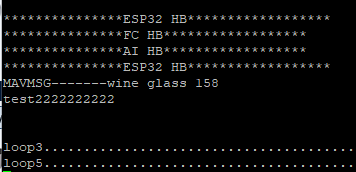
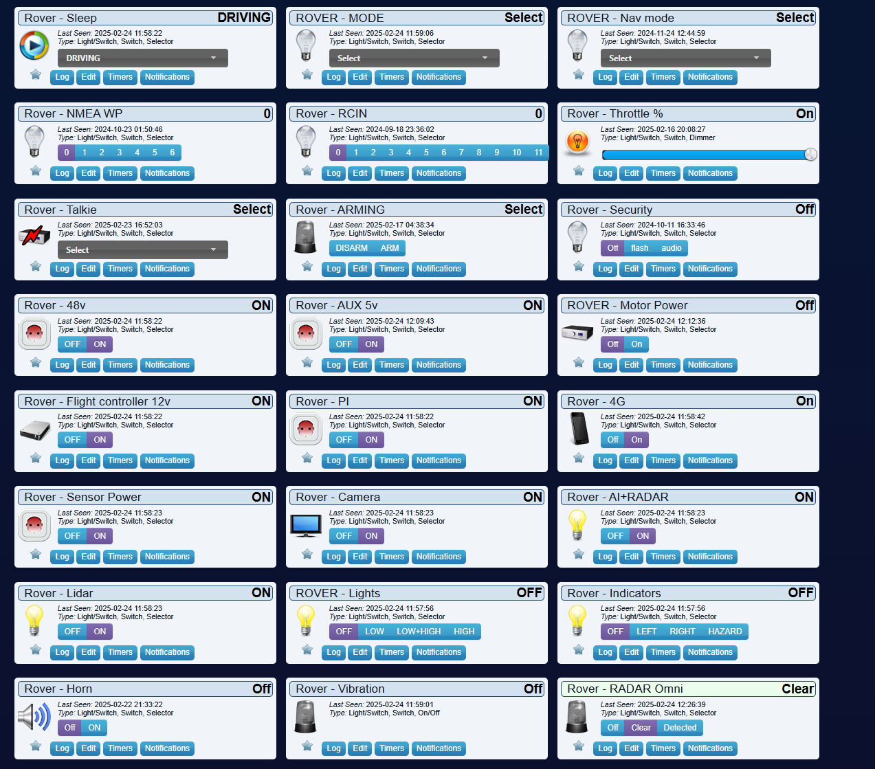

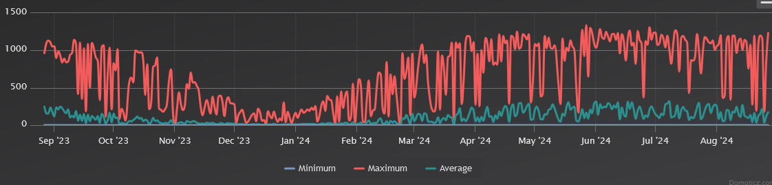
As you can see I can control most of the functions from here and im logging a lot, but there is still a lot more to do as this is just for the flight controller and the sensor controller i haven’t added logging for the lidar, radar, AI camera or the motor controllers yet. The main reason for this system is that mission planner and flight controller logs dont work when your talking time spans of months so i needed something better suited for long duration monitoring.
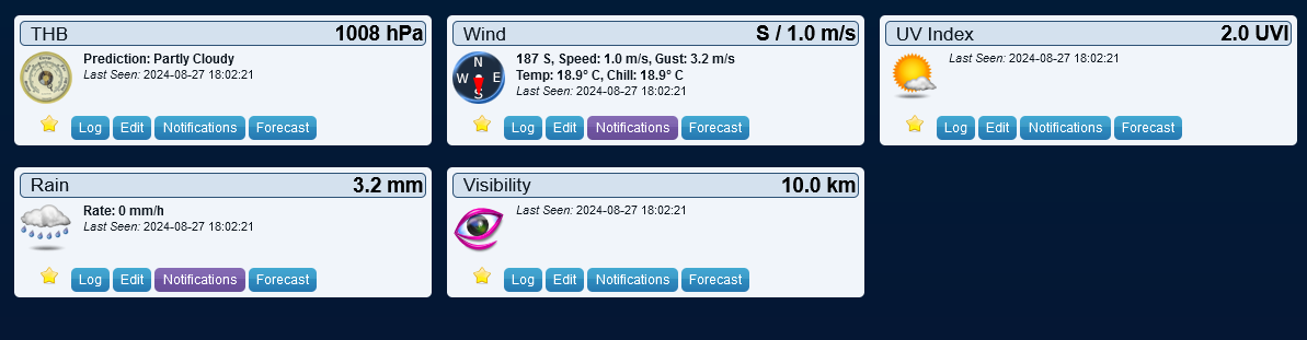
I have added a load of sensors onto it, sensors are cheap so I put them all on it, its pretty much a rolling weather station now
since its going to be unattended I added some basic security where it will flash its lights or sound a car horn if someone gets too close to it, the last few times it has been out OLD PEOPLE feel the need to walk up to it and tug on parts of it like the camera gimbal. I dont know why, there have been lots of kids and teenagers walking up to it and looking, taking photos, not one of them have ever touched it but old people walk up and start grabbing it and pulling on parts of it or even trying to lift it by the solar panel its like they dont belive its real, its happened multiple times now. its funny because I always get asked if I’m worried about kids vandalising my robot, but they have never once set a finger on it.
I am still working on interfacing with the battery BMS so i can get cell group voltages from the battery, I can send the mavlink battery data but i dont think there is a way of getting the flight controller to actually use it at the moment. also my efforts to interface to the bms didnt go well I think the library i found is for a slightly different no name BMS, even tho the same app works on both, or I have done something wrong but I’m not sure so im just going to install another matek I2c INA228 for the flight controller to use for now and il figure out the bms later, The way I will have it setup is the companion already has a pair for the battery and MPPT charge controller output. so I’m going to set this one up on the vehicles consumption with this I will be able to directly measure, how much power it’s consuming and how much is coming from the battery and solar. The sensor is bidirectional and has an internal accumulator, so it’s extremely accurate at tracking power over time. The flight controller was just using an analog sensor before now, they work fine under load but aren’t accurate enough to track for very low power levels. I also still need to setup the batt2 sensor on the flight controller to monitor the 12v rail.
I have added a lot of talkie text to speech to the esp32 using its interal DAC to genrate speech using some retro 80s technology the roms are from :
Texas Instruments Speak & Spell family of educational products
Texas Instruments TI-99/4A Speech System expansion
Acorn BBC Micro Speech Synthesiser expansion
Atari arcade games (eg. Star Wars series, Indiana Jones, Gauntlet)
Apple ][ Echo 2
IBM PS/2 Speech Adapter

there is about 1000 words you can use it would good if ardupilot could do this using the motors using dshot rather than just beeping.
I have a bunch of warnings setup that I can automate. so it can communicate by talking, it will:
read out the waypoints and what direction its going to go in to the next waypoint.
when it starts up it will announce a warning that its about to start moving,
it reads out flight modes.
when it’s parked and someone comes up to it will say why It’s stopped then read out all of its sensor information.

There is a way of making custom words, i want to convert one of the EDGETX voice packs at some point as i had to get creative with a few word choices.
I have been playing around with my amb82-mini AI camera, there have just been some new updates to its library so it now supports connecting to AI chat APIs for sending pictures to them and asking them to describe the picture and there is now an example for doing text to speech using googles translation API.
So for testing I have combined them so it takes a photo and asks if the path ahead is clear for the robot and to describe the situation, it can then read that out aloud.
I eventually am going to do something like have it send a photo for analysis if it detects something with the lidar or its basic neural network model to get a better idea of what it’s detected and if there is a way around it.
It’s not very fast unfortunately, it takes around 5 seconds to take a picture and get the results and another 5 to use the text to speech so to get it to take a photo and say the results takes around 10 seconds or more depending on your network so its not something that I will be using for real time navigation, but for something simple like “is it safe to move forwards”. it should work fine. It should also work as a logging system. Rather than having to stream video, it can just send some text with a summary of what it sees.
giving it this image
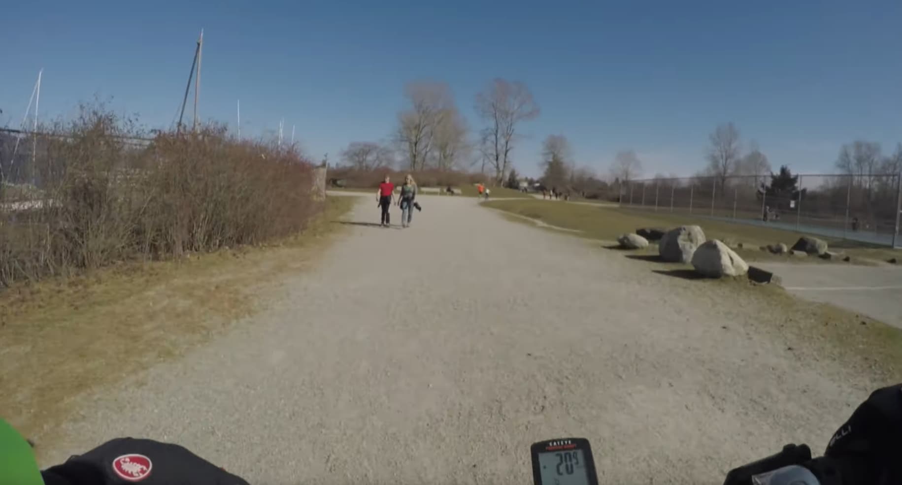
with the prompt "discribe image, is the path ahead clear, say STOP if any people are detected";"

this is a very cool video on how to make it voice controlled and interact with the world.
")
basically you need to give it a prompt with what it is and a summary of the last 10 interactions so it can keep track of whats happening. It should be possible to give it verbal navigation commands, and it can hand over the coordinates to autopilot.
String openAI_key = "";               // paste your generated openAI API key here
String Gemini_key = "*********************";               // paste your generated Gemini API key here
String Llama_key = "";                // paste your generated Llama API key here
char wifi_ssid[] = "********";    // change to your network SSID
char wifi_pass[] = "***********";        // change to your network password

#include <WiFi.h>
#include "GenAI.h"
#include "VideoStream.h"
WiFiSSLClient client;
GenAI llm;
VideoSetting config(768, 768, CAM_FPS, VIDEO_JPEG, 1);
#define CHANNEL 0


uint32_t img_addr = 0;
uint32_t img_len = 0;

#include "AmebaFatFS.h"

AmebaFatFS fs;
GenAI tts;

String mp3Filename = "test_play_google_tts.mp3";
String prompt_msg = "discribe image, say STOP if any people are detected ";

void initWiFi()
{
    for (int i = 0; i < 2; i++) {
        WiFi.begin(wifi_ssid, wifi_pass);

        delay(1000);
        Serial.println("");
        Serial.print("Connecting to ");
        Serial.println(wifi_ssid);

        uint32_t StartTime = millis();
        while (WiFi.status() != WL_CONNECTED) {
            delay(500);
            if ((StartTime + 5000) < millis()) {
                break;
            }
        }

        if (WiFi.status() == WL_CONNECTED) {
            Serial.println("");
            Serial.println("STAIP address: ");
            Serial.println(WiFi.localIP());
            Serial.println("");
            break;
        }
    }
}

void setup()
{
    Serial.begin(115200);

    initWiFi();

    config.setRotation(0);
    Camera.configVideoChannel(CHANNEL, config);
    Camera.videoInit();
    Camera.channelBegin(CHANNEL);
    Camera.printInfo();

    delay(5000);

    // Vision prompt using same taken image
    Camera.getImage(0, &img_addr, &img_len);

    // Gemini vision prompt for detection
 //   llm.geminivision(Gemini_key, "gemini-2.0-flash", prompt_msg, img_addr, img_len, client);

delay(5000);
    // Gemini vision prompt for detection then sending to text to speech.
    tts.googletts(mp3Filename, llm.geminivision(Gemini_key, "gemini-2.0-flash", prompt_msg, img_addr, img_len, client), "en-US");
    delay(5000);
    sdPlayMP3(mp3Filename);

}

void loop()
{
    // do nothing
}


void sdPlayMP3(String filename)
{
    fs.begin();
    String filepath = String(fs.getRootPath()) + filename;
    File file = fs.open(filepath, MP3);
    file.setMp3DigitalVol(120);
    file.playMp3();
    file.close();
    fs.end();
}
I don’t have an amplifier connected to the speaker so it’s very quiet .

My next step will be getting it to read out mavlink text messages.
1 Like
Now we are into spring and there is a reasonable amount of sunlight I have put the rover back outside for testing. It’s going to be in the garden for a month or so to work out any bugs before it goes further.
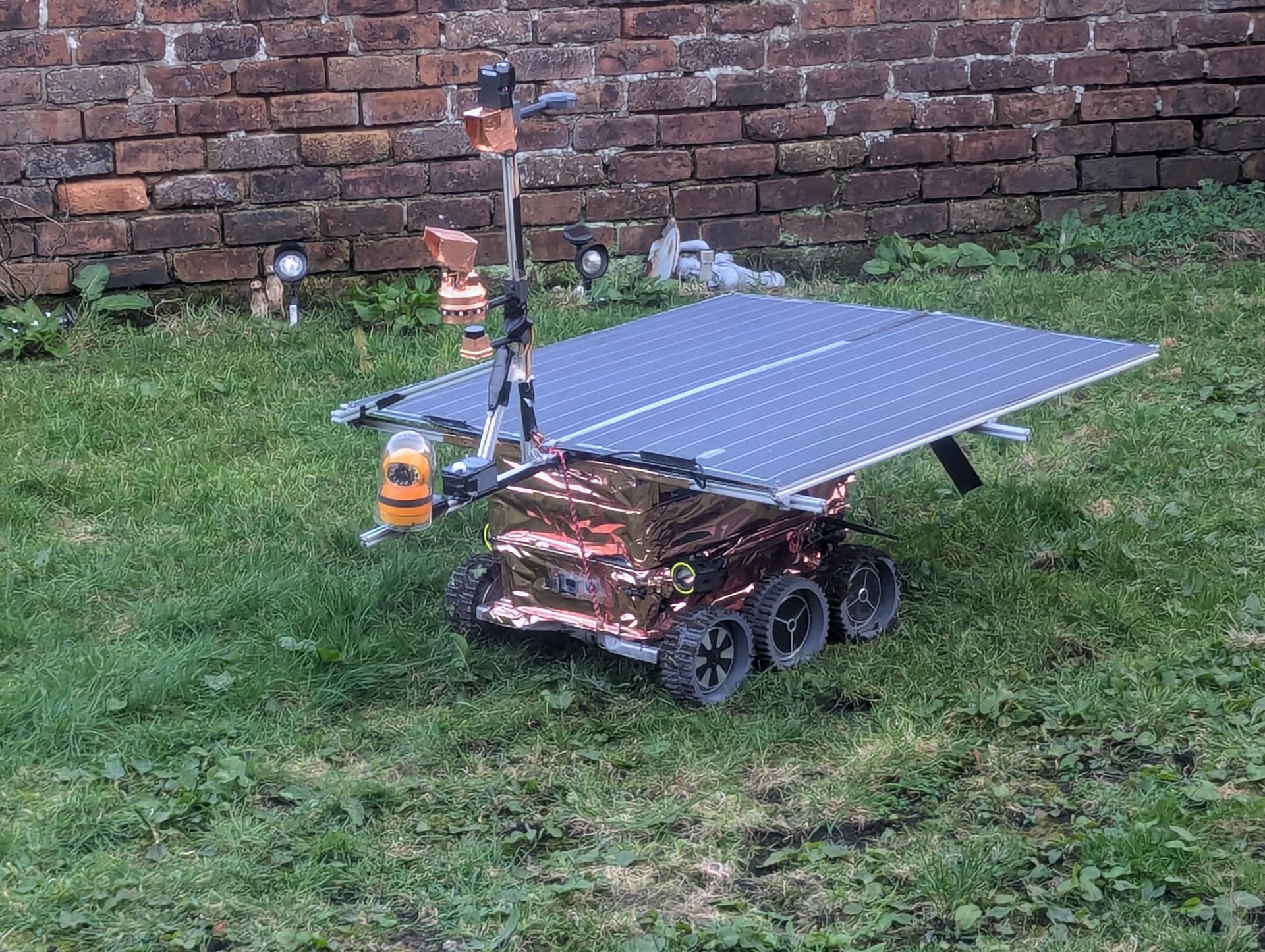
2 Likes
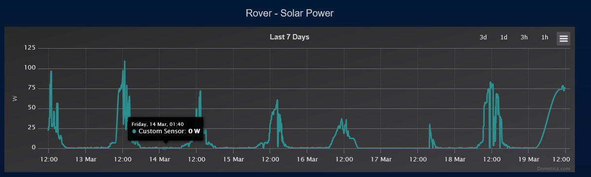
so its been over 2 weeks and I have made some discoveries…
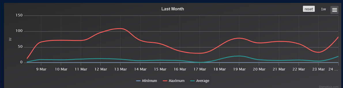
First is that my solar panels are junk, This is the first time the rover has been out with proper power logging and its showing that my panels aren’t even putting out 50% of their capacity. Its got 2x 100w flexible panels and im barely getting 100W, so I think they have picked up damage over the years like cracks so I will probably replace them with something like a single large 200W panel. solar panels have got much cheaper and efficient, so I can get a 200w panel now for about £70 compared to the £150 i paid for each of the panels on it.
at idle with just the esp32 and the modem its using around 6W but i think I can get that lower, I am replacing one of the relay boards with a mosfet board so it should reduce its power consumption a little and im adding a small 48v>5v 1a regulator just for the esp32 and modem, that will let me turn off the main 20A 5v and 12v step-down regulators as I think that’s what is using most of the power now at idle.
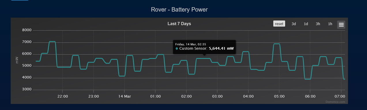
Consumption with the rover fully active with all the ESCs and sensors on is around 50W with spikes up to around 250w when turning on the spot and the wheels are digging into the grass.
ESC 2 has a fault where its feeding voltage to the RP2040 chip that controls them via its serial port causing it to not start occasionally. When this happened, I would need to remove the power for it to boot again by either physically disconnecting the battery or using the bluetooth app to turn it off and on. my plan was to connect to the BMS over serial to get the battery information and control, but the library I found looks to be for a slightly different BMS I need to investigate it more. I am going to replace the ESC but to be sure I have connected the BMS battery switch to a relay so I can switch it. The rover has a backup battery so it can switch off main power for short amounts of time.
I have rewritten the esc controller code so it has more sophisticated management of the motors, it can now detect and automatically alert and deal with a few issues like if the controllers are overheating It will turn the overheating ESC off when its critical, and back on once its cooled down.
if any motor is running slower than the rest of the wheels on its side or if any of the motors are stuck it will send mavlink alerts.
Rather than controlling the ESC power switching directly from domticz it’s now fully automatic-
when the rover is disarmed, all the ESC’s will be off,
when the rover is armed and in hold mode, it will only start the centre ESC to use it as a brake to keep it from rolling.
When the rover is armed and in any other mode, all the ESCs are on.
The 3d printed gimbal mount that sits above the lidar snapped when it was going over some bumps, when it dropped, it covered the lidar, blinding it and causing it to crash into a plastic garden chair. so i reprinted the mount with some internal bracing and support so it doesn’t snap at the same place again. im going to add a backup rangefinder, probably a sonar in case something like that happens again. It also shorted out the 5v when it pulled the wire off of the led strip as it fell causing problems for all the other devices on 5v. So I am going to add some 1A poly fuses to all the 5v devices, that way if something totally shorts it should recover.
The ld06 lidar is still having issues in the sun, I have the filter at 200 out of a maximum of 255, and its still useless in sunlight so next time it’s in I’m just turning it up to 255 and hoping for the best. If that works then I can use the onboard light level sensor to dynamically change the filter depending on the ambient light levels.

The radar/AI camera combo works quite well as long as they are directly ahead or close up, the 2 neighbours were in the garden and I could see them moving around on mission planner but the camera has a much wider fov than the radar the further out it is so once something gets to the edge of the screen and the radar cant detect it anymore it gives the range of the next object like the wall that’s usually much further away. I belive this is the problem the v1 tesla autopilot had with its mobileeye+radar system as it would pick up objects with the radar and fail to fuse that with the camera data.

im happy to report that the matek flight controller has been behaving, now its connected to a relay with no accessories powered from it, I havent had any memory corruption since i have isolated it. the only connections to it are mavlink serial, 12v and canbus.
My domoticz control system is working, It can automatically wake up the rover, arm it, set auto mode. drive for a set time disarm and once the voltage gets low then it will set it to go to sleep automatically.
at the moment im using a lot of delays to get everything to start up in the correct sequence, so flight controller, then accessory controllers, cameras, then the ESC’s, but that’s not ideal, I’m working on adding feedback to the startup sequence so it checks each component as it’s turned on for the correct feedback to check its started correctly before moving to the next, there is no point turning on the ESCs if the flight controller isnt detected.
it’s been over 2 weeks now outside, so it’s getting brought back in today for its updates. Changing the ESC, adding mosfets, software updates and some minor rewiring it should be back out in a few days time.
I don’t believe this, maybe these modules not last state of the art, but…
The nominal capacity shown in the data sheets are only a theoratical value which is never ever reached. This value is only for comparsion of different modules. It shows the maximum power earnt under direct absolute clear sunlight with 1000W/square meter comming absolute ortogonal to the panel.
This can’t be reached with your setup under normal conditions.
To check if the panels are defect you can compare the two modules against each other as the both has mostly the same light conditions. So if the output (voltage and current) of both is nearly the same they are most probably ok as they don’t will have the same defect.
2 Likes
I dont have any power monitoring on that side of the mppt controller but unplugging one at a time should give me a good idea if it’s just one terrible panel or both are struggling.
Are the two panels parallel or serial connected to the MPPT charger?
1 Like