Mini ArduPilot Antenna Tracker

Although my original ArduPilot Antenna Tracker from 3-1/2 years ago is still working, I decided to build a smaller DIY table-top version using newer less expensive components. There are many different choices for components so feel free to post your own versions as some of my choices were made from components on-hand.

The basis for my Pan/Tilt/Zoom mechanism (a.k.a. PTZ) is the LOBOT 2DOF Rotary PTZ With Digital Servos from Banggood. It comes with two LD-1501MG Digital Servos for only $38 U.S. with a choice of colors. The LOBOT LD-1501MG Digital Servo has a range of torque from 13KG to 17KG on 6.0v to 7.4v, respectively.

1 Like

My original ArduPilot Antenna Tracker (AAT) used an ImmersionRC (IRC) Duo 5.8GHz. receiver. This worked well by utilizing both a patch antenna for longer range and a clover-leaf antenna for shorter range or when the AAT was not plugged in. I found a smaller, less expensive Skyzone RD945 for $20 at RC-n-Go.com/.


The price of the IRC SpiroNET 5.8GHz 13dbi LZR Patch Antenna has come way down over the years so I picked one up at ReadyMadeRC.com for $25.


While waiting for my LOBOT 2DOF PTZ unit to arrive, I tested the latest ArduPilot Antenna Tracker build out on my RadioLink mini PIX with a couple of spare servos.


Both the mini AAT and MavLink vehicle were in my backroom for the test so they were too close for tracking but the test page worked well for the servos.

I was happy to see the battery monitoring feature fixed after all these years. Thank you Peter Barker and Peter Hall!
@peterbarker
@iampete


My APM vehicles all use 915MHz. telemetry so this is how my AAT connects to them. The GCS or laptop is connected via a 433MHz. telemetry set as shown above. This functionality is right from the Wiki section called, Connect a 2nd pair of radios. I just changed frequency bands for my GCS connection. Note that my 915MHz. air telemetry link and 433MHz. GCS telemetry link to the AAT also use different Net IDs.


The SiK radio settings above have proven to be the most reliable on my other AAT so I also used them for this project.

Ultra Pod II
The Pedco UltraPod II Table Top Tripod can be picked up for about $24 on Amazon or used on eBay for only $10. They make a nice holder for the monitor.

2 Likes

My LOBOT PTZ package arrived and I was very happy with the quality of the components. For only $38 with two large servos and all the hardware, it seemed like a great deal!

I did a rough assembly of how I envisioned placing the components. There was plenty of hardware left over and BG has a bunch of PTZ Brackets to add onto the assembly, if desired.

My monitor is powered by a small 2s Lipo in the back and a single cable connects A/V to the RD945. I’ll likely change the 5.8GHz. omni antenna to a circular polarized antenna. One 3DR telemetry radio is on 915 for the ground-to-air link and the other is on 433MHz. for the tracker-to-GCS link just like in my original build. I need to find a place for my ATT LiPo pack next…

RF adapters and cable connections came from ReadyMadeRC.

2 Likes

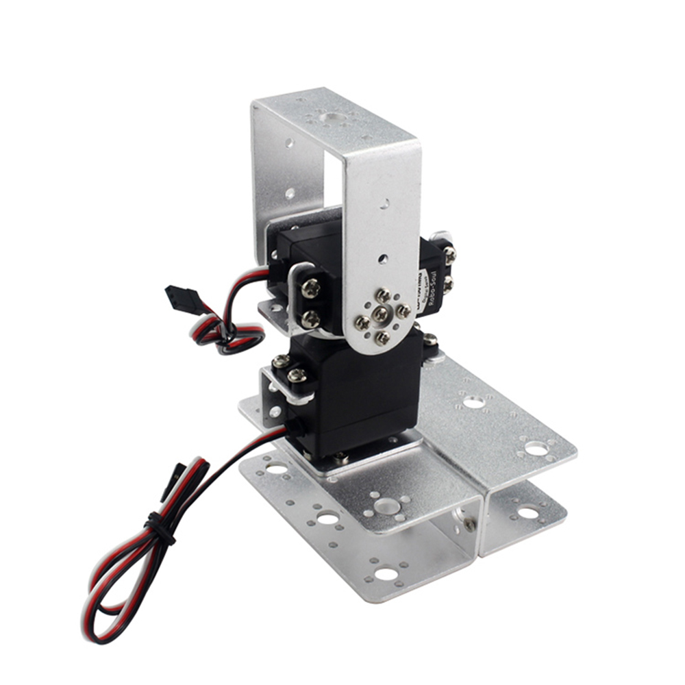
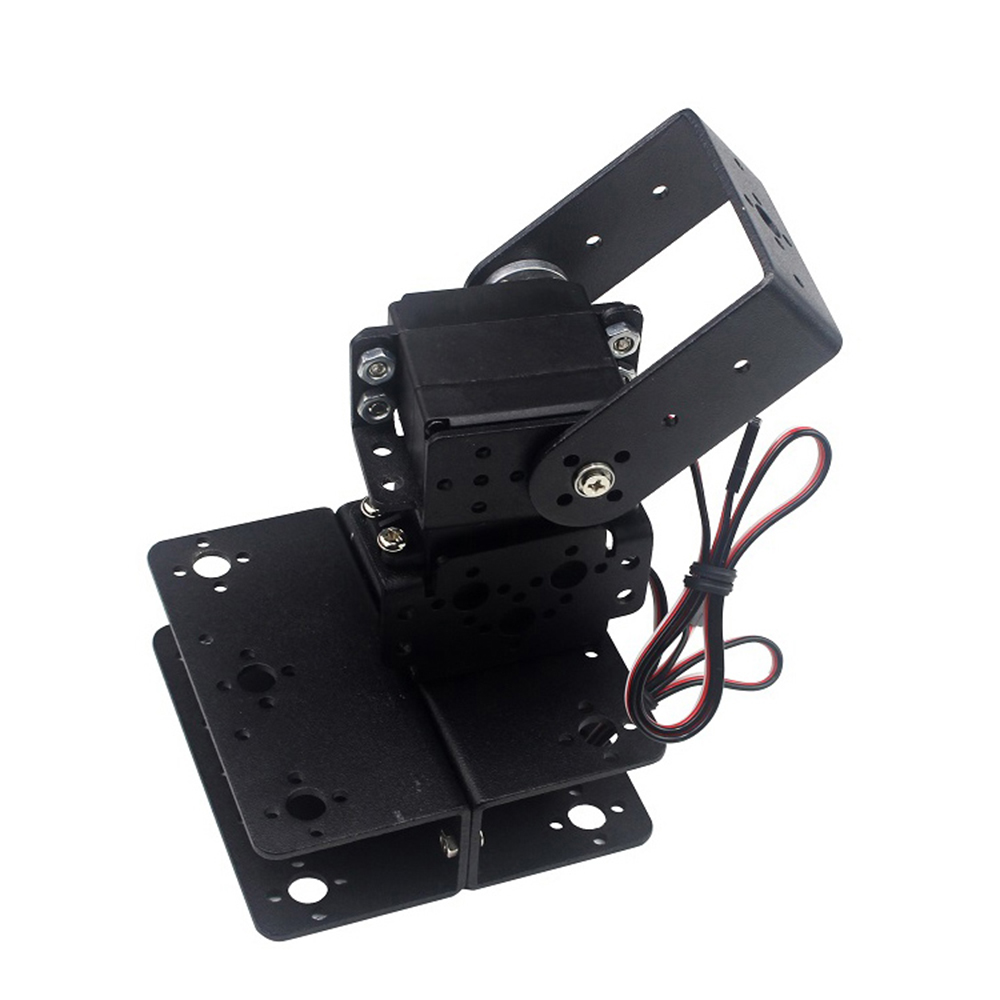
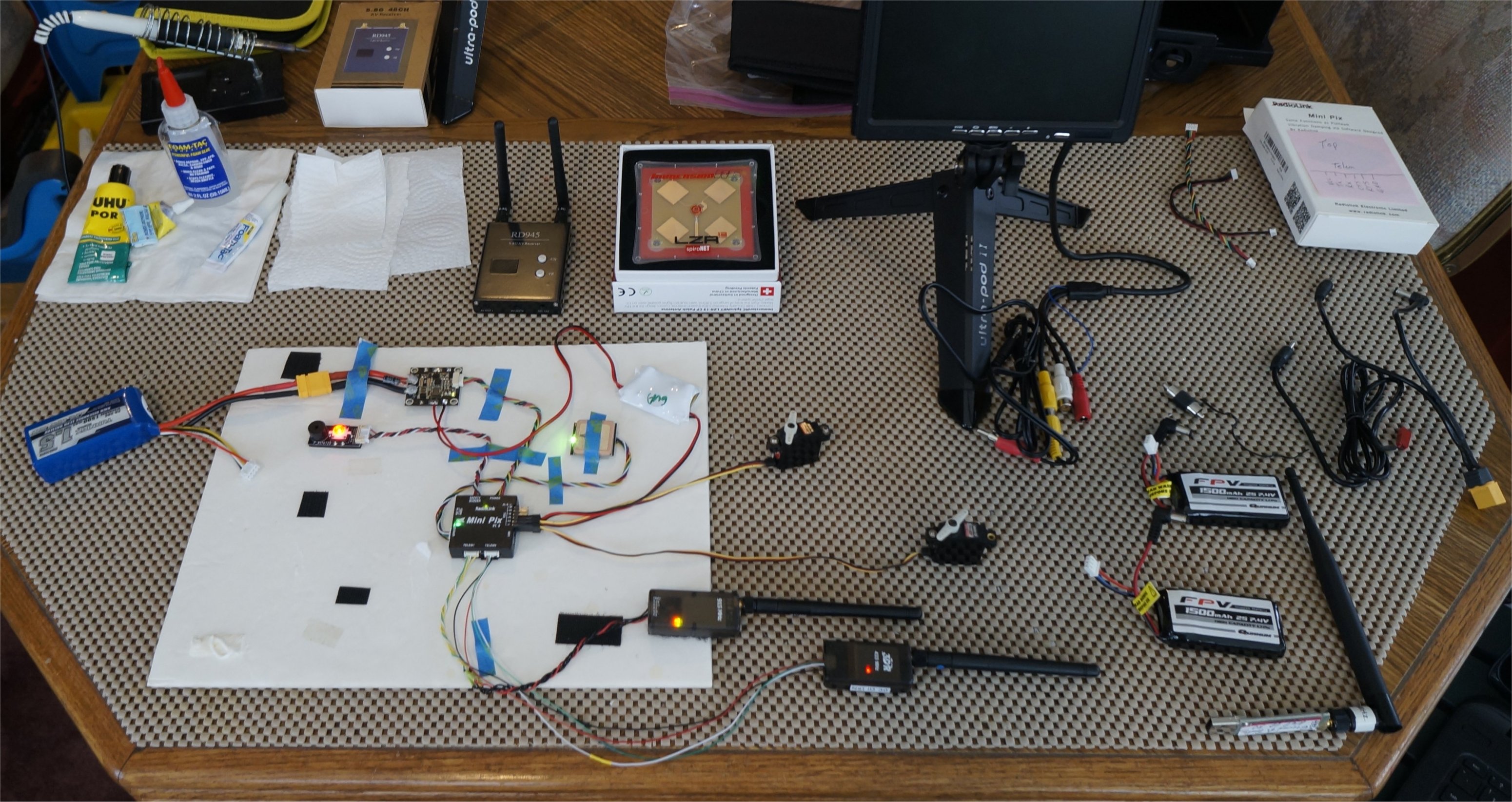
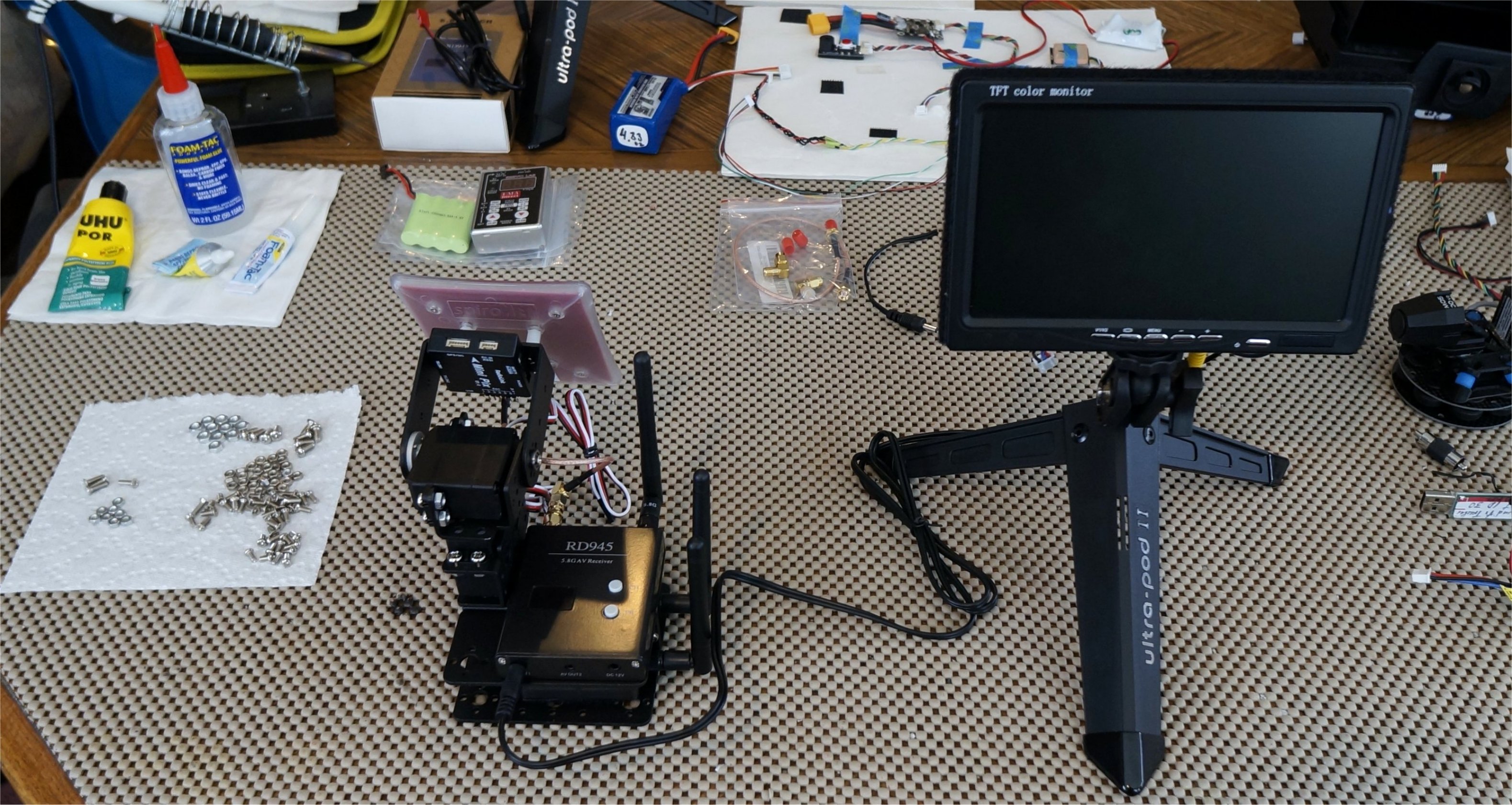
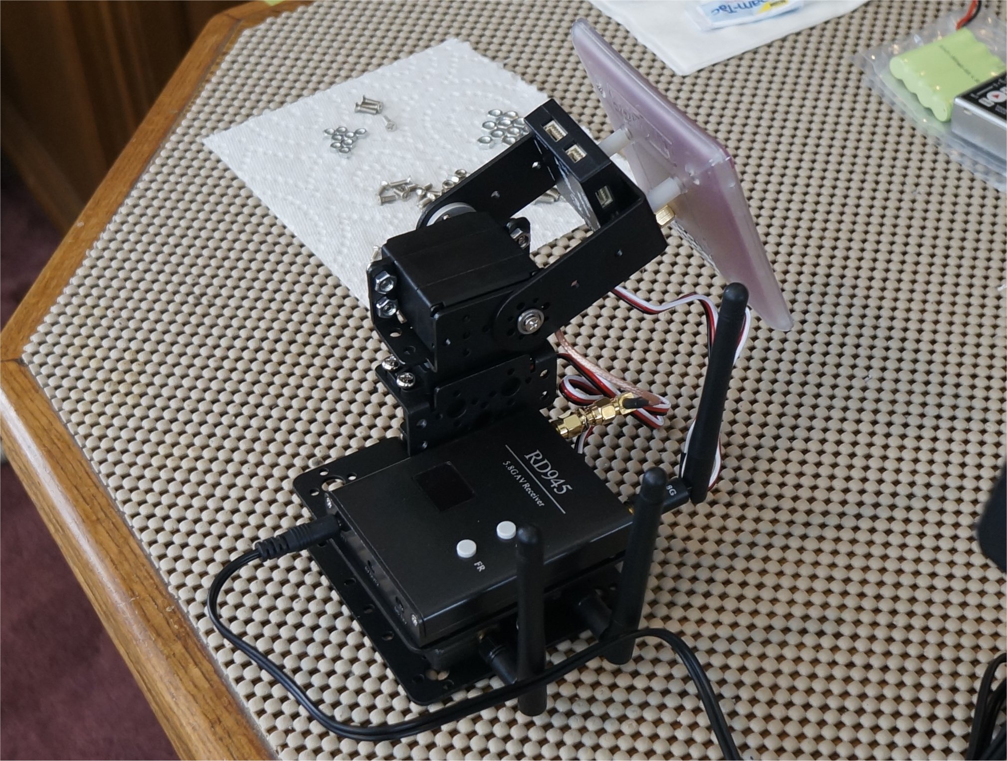
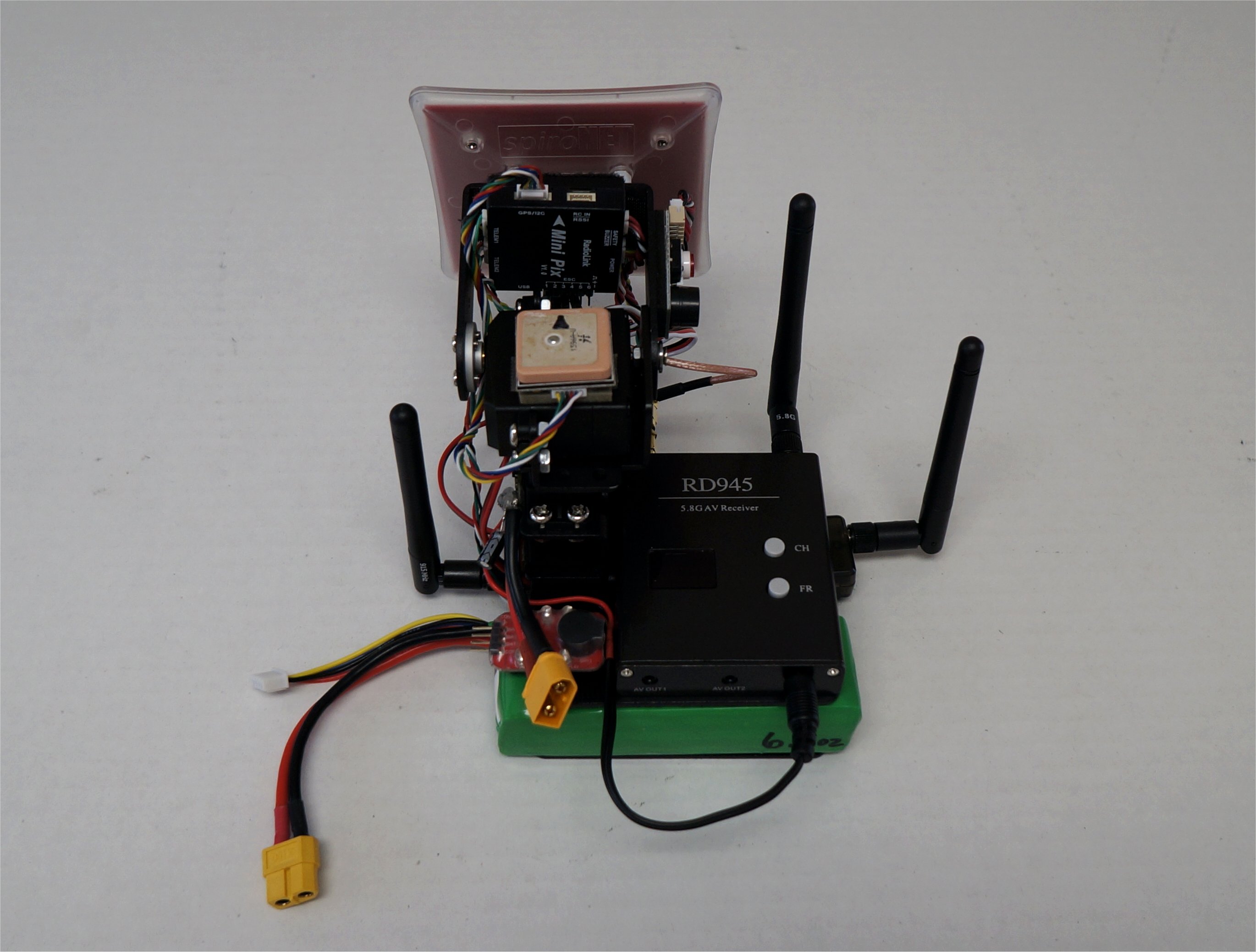
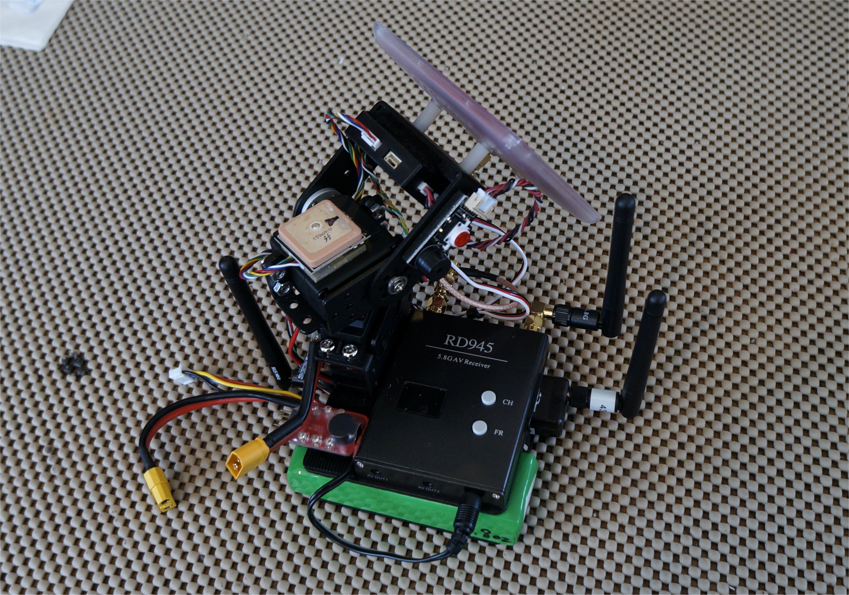
Since I had previously set up my mini PIX for the Antenna Tracker, it was mostly a plug-n-play assembly to finish things off. I found an older Multistar 3s 3AH pack that fit perfectly in between the base bracket plates and the 10C discharge rate fit the AAT’s current requirements. I use a $3 Lipo Battery Low Voltage Alarm Indicator from BG to keep the battery safe.

I did run into one big issue, which was changing over to the internal compass on the mini PIX. The Antenna Tracker firmware would not allow me to do this using Mission Planner v1.3.70, nor would it even calibrate either compass. My solution was to load the latest Copter 4.0.1 code into the mini PIX which allowed me to properly calibrate both compasses using the Onboard Mag Calibration. This hint came from the mini PIX Manual, page 17. I then saved this parameter file. The AAT firmware was loaded back on, along with my originally saved AAT param file (see below), and I manually entered the calibration values for just the internal compass. Some of the parameters below are read-only just for show. The main values entered pertain to compass #2.

See Post #7 as this process is not needed to calibrate the compass!

COMPASS_AUTODEC,1
COMPASS_CAL_FIT,16
COMPASS_DEC,-0.2421951
COMPASS_DEV_ID,855305 (external compass)
COMPASS_DEV_ID2,855297 (internal compass)
COMPASS_DEV_ID3,0

COMPASS_DIA2_X,0.9838372
COMPASS_DIA2_Y,1.003144
COMPASS_DIA2_Z,1.005739

COMPASS_ODI2_X,-0.005123704
COMPASS_ODI2_Y,0.02832997
COMPASS_ODI2_Z,0.009586642

COMPASS_OFS2_X,79.63103
COMPASS_OFS2_Y,110.178
COMPASS_OFS2_Z,50.07391

COMPASS_USE,0
COMPASS_USE2,1
COMPASS_USE3,0

miniAAT4.param (8.7 KB)

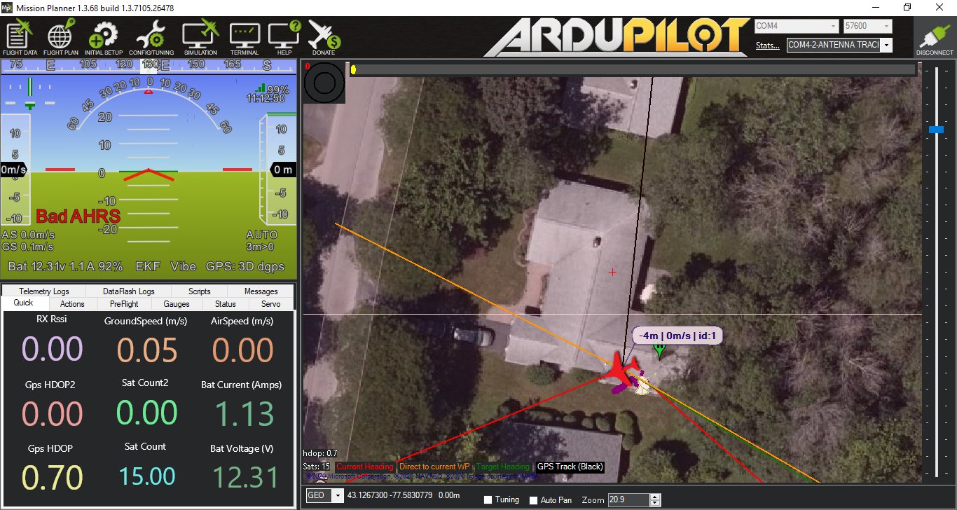
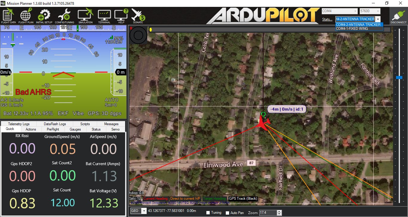
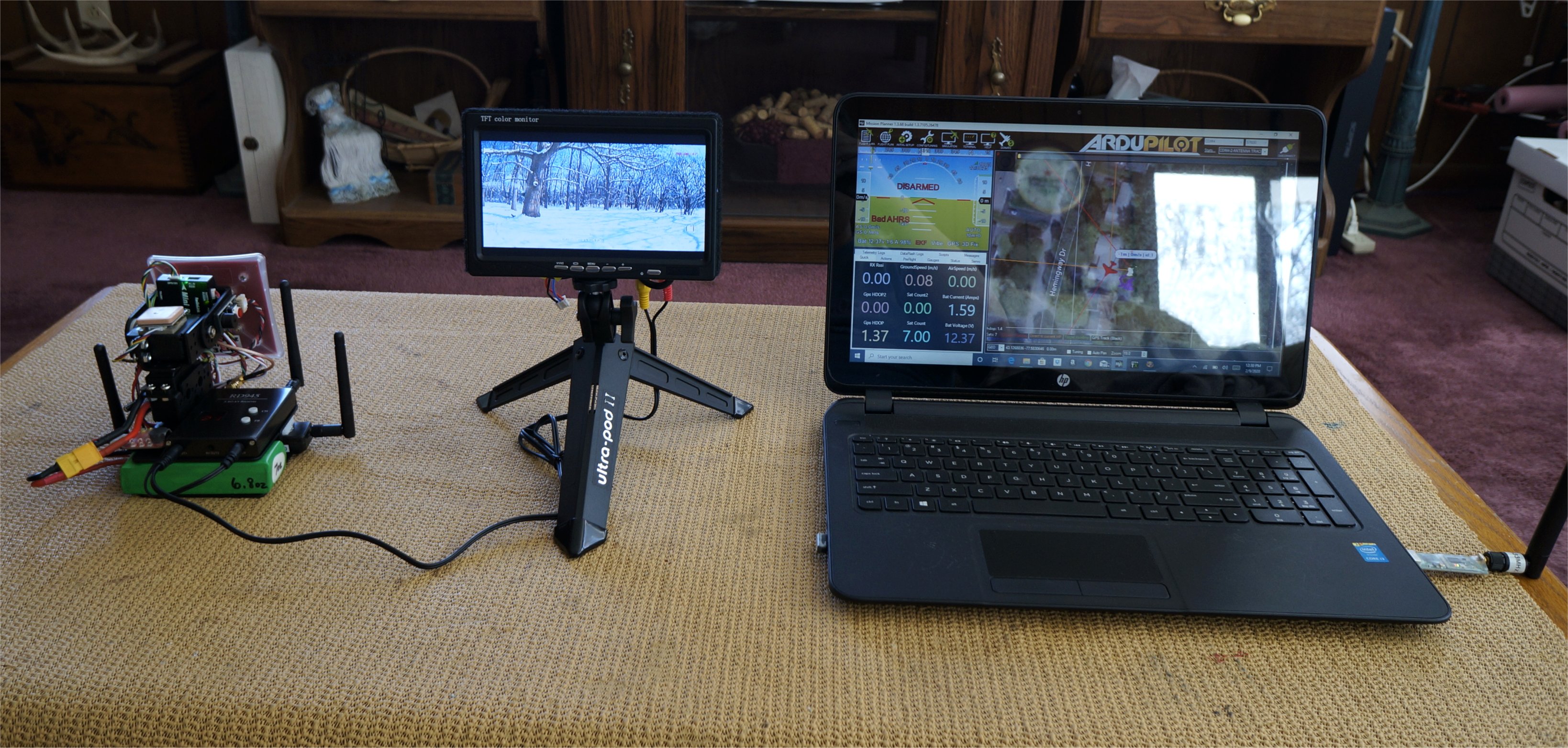
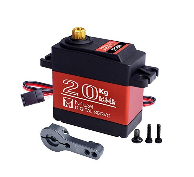
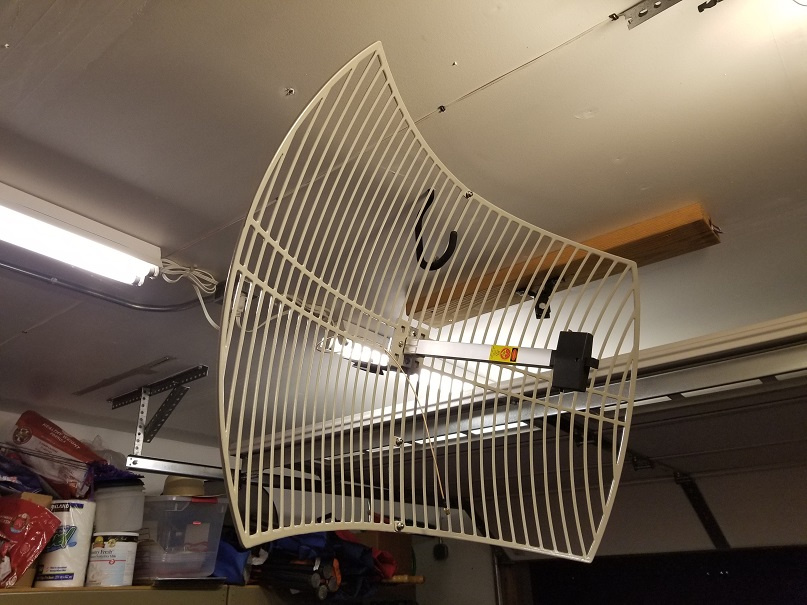
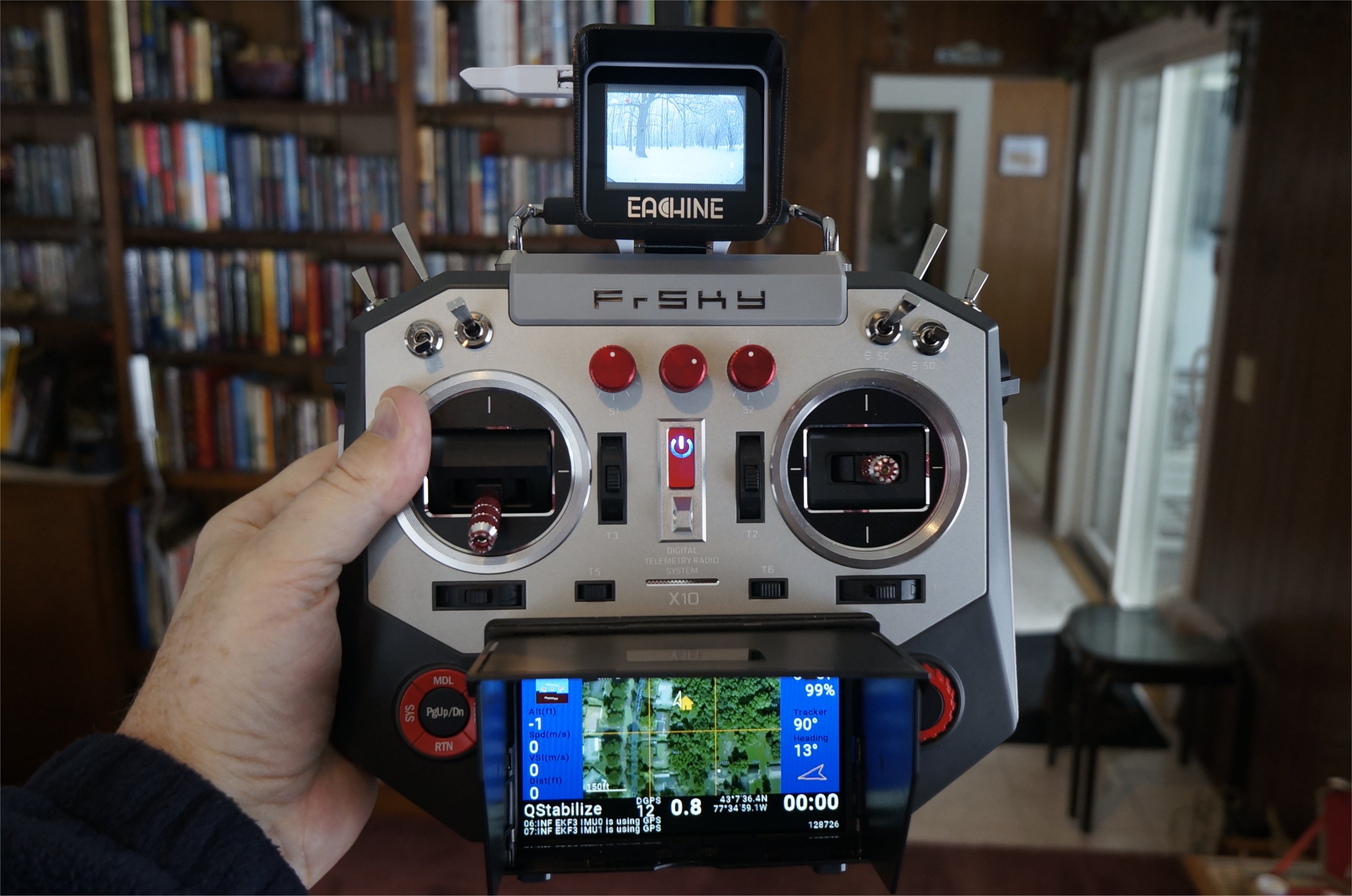
I got some better separation between the AAT and Plane by putting the plane in the garage. It’s cold and snowy here so no outside testing yet. Anyway, it was far enough to get the tracker working and the yaw worked quite well. One limitation I found with the supplied servos is that they appear to be only 90 degrees servos. This is fine for pitch but may be too limiting for others on yaw.

1 Like

Hello Greg,
you can test the real tracker with a simulated airplane (In MP use a quadplane for simulation and connect this plane with your real tracker). With a short flight plan (VTOL_TAKEOFF, DO_VTOL_TRANSITION mode 4) you can start the plane without a joystick - just set mode auto and arm. Then right-click on the map let the virtual plane fly wherever you want.

For tests without GPS reception, you can set the tracker to a fixed start coordinate (parameters START_LATITUDE/LONGITUDE)

1 Like

Thanks, Rolf. I assume that you are referring to SITL. I’ll check it out…

So there seems to be a simulator built into MP…very cool! However, when the plane is flying in Guided mode, it does not seem to move the AAT. It’s as if the plane is using a tcp connection and not the 3DR telemetry link to the AAT.

I also tried setting up the MP Simulator on a separate PC but that didn’t connect to the AAT either. I guess that I am not sure how the simulated plane connects to the AAT.

Ahh, found it! Under the “Testing Screen” in the “Planner” screen checkbox is a MavLink button that can mirror the MavLink stream to any Comm port. In this manner, the simulated vehicle is broadcast out the 915MHz telemetry model which then connects over-the-air to my AAT. This is way cool and my AAT is working great!

From the Simulator:

Simulator3

From the AAT below:

I found this work around above from Adam_Kelly for calibrating the compass or running the ACC calibration. It is certainly less steps than my manual parameter copy process using a Copter or Plane installation.

The stock LD-1501 servos have about a 100-110 degree rotation. This is fine for the pitch but I wanted a bit more for the yaw movement so I decided to order one of the DS3218 servos from Amazon below. These have a 270 degree rotation. Banggood sells both a 180 and 270 degree version but with Amazon I can get it tomorrow with free shipping. It will be easy to replace my stock servo so we’ll see how it works!

Miuzei 20KG Digital Servo Motor High Torque Servo , DS3218 Control Angle 270° - $16 on Amazon
DS3218 PRO 20KG 180° 270° Waterproof High Speed Metal Gear Digital Servo - $17.62 at Banggood

Hey Greg, you responded and put a link to your site in the Ardupilot thread on RCG.

I like your little antenna tracker. For a good year I planned to make a larger tracker to handle a 1.2GHz grid and 433MHz panel or yagi antenna. Ordered and now have the large geared pan units with Hitec servos from Servo City. Will use a surveyor’s tripod for the base.

I looked at the BG PTZ you linked and are using and it looks good. One thing I don’t like about these setups though is the tilt assembly rests entirely on the pan servo output shaft. So here’s what I’m doing for both the big and small trackers I’m building.

These bearing plates are dirt cheap on Ebay. I ordered one of each of the three larger sizes.

The pan servo will be mounted in the center with a connecting plate from the servo wheel to the top bearing plate. The tilt servo will then be mounted to the top plate. So no pressure on the servo bearings. Small pressure on the small tracker but the larger one will have additional bearings on the tilt mechanism.

I have a few different telemetry systems including the EzOSD with tracker, Vector with tracker and APM / Ardupilot controller for Mavlink. Just need to finish up other projects to get to them.

Hi Jeff,

Thanks for sharing your ideas! I started out using an IRC EasyOSD tracker many years ago but got tired of the need to re-calibrate on every site flown. The APM tracker functionality allows you to simply place the tripod facing any direction.

The antenna size certainly increases with lower frequencies! For my smaller 5.8GHz. antennas, there is almost no weight on the yaw (or pan) servo shaft. I do like your bearing plate scheme to offload the weight of larger antenna tracker mechanisms. It should be fun to modify your Servo City Pan/Tilt mechanism.

The two things I have learned from this newer project are that the battery monitor reading has been fixed and that Mission Planner has a built-in Simulator that makes for easy indoor testing during the winter months here in upstate NY.

Good luck on your project!

Upstate NY is a beautiful place. I’m over in Utah so similar climate for the most part.

I wasn’t aware there were such calibration issues with the EzOSD. I have several flight controllers for Ardupilot and the Vector but just had the EzOSD on my list ready to order. The plan was to have one simple standalone system that could be easily installed in small, short to medium range aircraft. Maybe my thinking was too simple and I’ll just stick with setting up those aircraft with Mavlink.

If you don’t mind sharing your thoughts, I was wondering what you think of the SkyDroid system. I hadn’t even considered it before but am currently building a 1066mm folding heavy lift quad that will be used to recover NWS weather balloons and the SkyDroid looks interesting. Currently the electronics planned for the quad are a Matek F765-Wing (ordered), 433MHz OpenLRS for control and telemetry and 1.2GHz video. I would like to get the new RadioMaster T16S in order to display telemetry and moving map.

The quad will drag a 30ft or so cable with a servo-actuated grappler so I don’t foresee trying to do recoveries farther than about 3-miles out because of likely RF degradation needing to be that close to the ground that far out. Will depend on the situation, of course.

Having a high definition video link would be a huge plus with this project. Currently I’m planning to use a GoPro with gimbal up front and a GoPro or other camera at the back on a tilt platform so the camera can be aimed at the grappler. That camera will use a 25mm lens to better see what I’m doing.

If you want to respond someplace else as to not clog up your thread here that would be great. The thread I started on the project is here. Also building a V-bicopter you might find interesting. As a matter of fact I’m printing a final prototype bottom plate motor arm and FC mount right now. And of course since those aren’t enough I’m also working on several other custom projects including an FX-61 tail-sitter. There are just too many cool things to try.

It’s great to have people like you in the hobby.

I currently have the Skydroid M12/R12 system mounted on my Tarot 680 Pro hexacopter. It works well although I don’t fly copters much anymore. Mostly, I fly VTOLs with my FrSky Horus (see last two images) and Taranis X9D+ transmitters. Much of my choice comes from being more familiar with the FrSky transmitters and Yaapu telemetry displayed right on the screen. I keep a tablet or laptop nearby for GCS functions, if needed. The balance of a tablet or phone on the Skydroid transmitter is very nice and I have no complaints on performance in a few miles. I don’t fly farther than that.

I saw a few of your posts in the SkyRadio thread. It’s mostly FrSky and OpenTX for me as well mainly because of the ability to modify and adapt it to whatever. I suspect that Yaapu script is the same one I saw used in a Jumper T16 flashed with OpenTX. Same script I plan to use with the T16S. The Horus is really nice but outside my budget for a radio. I’m using a couple of 9D+ and several Futaba’s for various plane and camera platforms.Of course in hindsight getting one nicer radio could have replaced a few of the others.

I would certainly like to ask more questions but know that the answers to most are out there in cyberland somewhere so I’ll start searching. I’m a former tech entrepreneur and started in the hobby about 30 years ago but a lot of the current tech in the hobby is pretty advanced to just “figure out” without expert advice.

BTW, I have a 680 Pro as well. Traded a guy a Ranger 1600 for it, since I had two of them. Have no idea what I’ll use it for. Thought about using it to launch gliders. Haul them up, release, switch on RTH and fly the glider. One man show.

My DS3218 servo arrived and it was an easy swap for the original LD-1501MG servo. Although it was stated to be 270 degree rotation, it was really around 200 degrees which fit my goal just fine. Like the stock servo, the performance was absolutely fantastic (indoors) using the default APM Tracker PIDs but I now had my 180+ degree swing on the yaw.

Below, the Mission Planner’s built-in Simulator makes testing the AAT very easy!

Hi,
I saw below page and doubted that Mini pix not Support antenna tracker.
https://ardupilot.org/copter/docs/common-radiolink-minipix.html

Does it support antenna tracker the situation right now?
I work with ardupilot and mission planner.
Thanks

1 Like

Hi Sadegh,

Yes, the RadioLink mini Pix is always included in all the updated builds. You can find the latest build below. I downloaded the firmware to my PC and then used the “Custom Firmware” link on Mission Planner to upload it into the mini Pix.

AntennaTracker_latest_mini-pix

Cheers!

Thank dear Greg

Blockquote

Hi, Antenna tracker need Gps? its better have gps or no?
Thanks

Strictly speaking it does not; you can specify its position.

Life it going to be easier if you have one :slight_smile:

Yours,

:slightly_smiling_face: :+1:

XionUAV,

Saw you mentioned a Surveyor’s Tripod for the tracker, how are you mounting to it?

Rusty