Building a Better Quad Frame

Purpose

To design and build a better quadcopter/X8 frame that is open-source, light, strong, versatile, and is especially suited for DIY builders who have a limited budget and only basic tools. ALSO, to list properties and guidelines that can be used to improve ANY type of copter frame you want to build.

Contents

This is an educational blog. Here are links to my main posts, between sections of comments. I do encourage everyone to read the comments because there is some great input from the community.

  1. Quadcopter Frame Types
  2. Prototype Frame Outline
  3. An X is Your Best Friend
  4. Don’t Believe The Hype
  5. Prototype Frame v2.4.7
  6. Square Tubing vs Round Tubing
  7. Motor Mounts… Please Help!
  8. Nylon Bolts? Really??
  9. Packing Material and Drone Design

More posts coming soon!! Sometimes I have to work and sleep and stuff.

Project Goals

  • Design a frame with open-source plans and 3D models, allowing many people to 3D print or produce their own parts as needed, using readily available materials.
  • Describe ways to make a lighter frame to increase flight times and/or payloads.
  • Describe ways to make a stronger frame to minimize damage during crashes. Because, lets face it, most of us crash.
  • Design a frame optimized for photography and filmmaking but can also be used for a variety of purposes like mapping, etc.
  • Get input from ArduPilot software and hardware developers for design revisions and customizations so everything works together more efficiently.
  • Build a prototype, test and refine it, then work on production methods.
  • Personally, I want to support Ardupilot, The Cube, and anyone doing SOLO “brain transplants”.

Project Background

I’m disappointed with the frames currently available. They’re heavy, they aren’t stiff, and many don’t do well in crashes. Some are easily repaired, while others are not. Sometimes you have to buy a whole new frame kit just to get the parts you need. I constantly see weight being added that does nothing to improve torsional stiffness or minimize crash damage. Meanwhile, engineering techniques commonly used in bridges, towers, and full size commercial aircraft, are ignored.

I’ve spent the last 3 years building my own frames from scratch as well as modifying commercially available frames. I’ve crashed and smashed quite a few of them. I’ve tested materials. I’ve tested adhesives. I’ve built test stands. I’ve asked many questions. I’ve learned a LOT from some really smart people who have a lot more experience than I do. I feel like this is the next step.

About the Title Photo

“Drogon v1” was my previous frame. A recent crash proved some things I already knew and it revealed some new things as well. While it was easily repaired, I decided to take what I learned from it and start a new build. This blog will document what I’ve learned so far, as well as what I learn from the new build.

My next post will outline details of my prototype frame but here are some rough specs:

  • “Hybrid H” design (like the SOLO) with roughly a 690mm wheelbase
  • Symmetrical layout (same distance between front/rear and left/right motors)
  • Optimized for 15" props, clearance for 16" props
21 Likes

How do we stay informed? I am finishing up a x8 build that is flying the solo link hardware
Payload is a Zcam E1
Once I prove out the concept and document the build, I want to move to 6S and will be in te market for a new frame

2 Likes

I figured this is a blog, so I’ll be adding posts as I go. Look for my next post later today. I like your build! Do you know what that frame weighs by itself??

just the frame about 900 grams

1 Like

Strong vs light, ever is like this, should be light, and a crash is better when every piece is smaller than an inch, means it was light and you will not fly any rebuilts with hidden damage.
Anyway the goal should be redundancy as comercial aviation, and security factor of frame nearing 1.

1 Like

I have build my own multirotors in the last 8 years,

My most efficient quad with 15" -16 " props can reach with 250 grams of payload a flight time of 50-60 minutes depending on the battery size , standard batteries no Li-Ion, and an efficiency of 11,6 grams / Watt

870 grams is the total weight without batteries and payload , but with landing gear, all electronics , 433mhz telemetry and a plate where to fix the camera.

But the best quad frame you can build is a monocoque carbon fiber frame.
I have done it 6 years ago, I name it “the frog” .
160 - 190 grams for the frame without landing gear .
Very stiff and resistant to crashes .
But the mold cost me close to 2000 $.

I barely stopped to deal with multirotors since people seems so happy with DjI stuff , and very few seems to be interested in flying more that 45 minutes and pay for it.

2 Likes

All good points and I agree with everything you said. I’ll be covering all of the topics you mentioned.

My previous ship used 380kv motors with 15" props and flew for 40 minutes with a 8000mAh lipo. That was also with a 250 gram payload.

Monocoque is the way to go but very difficult and expensive for DIY people, including myself. I’m going to see how good I can get first without going monocoque.

02 - Quadcopter Frame Types

(each main blog post has a number and title to set it apart from replies and comments)

I want to make this blog educational for beginners as well as appealing to the seasoned pros who’ve been doing this longer than I have. If you see any mistakes in my math, please let me know! :smile:

First, I wanted to illustrate the differences in the basic frame types you can build yourself. I’ll cover more complicated stuff in a bit.
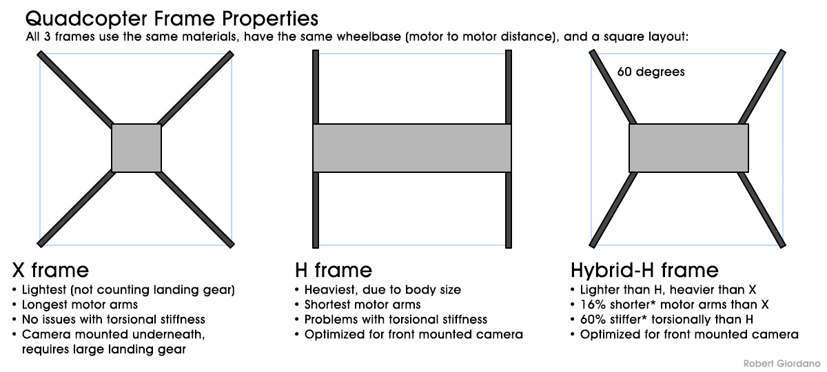
X Frame

This is probably the most popular and common frame type in the DIY world and its the easiest to build. All other things being equal, it will be the lightest frame. The thing is, you’ll be hanging the camera underneath the center and it has to hang low enough so you don’t see propellers when its pointing forward. If you plan to point your camera down most of the time, or it doesn’t matter if you see propellers in your video, then an X Frame might be the best for you.

If you don’t want to see propellers in your video, then you’ll need some fairly long landing gear so your camera doesn’t hit the ground on takeoff and landing. The problem is, the landing gear needs to be fairly strong to support the weight of everything else, so it becomes heavy. The weight of your landing gear can easily cancel any weight savings you get from the X design.

This frame will have the longest arms, compared to the other two frames and as I recently tested, longer arms are more prone to bending, and they act as levers in a crash. The longer the lever, the more force it exerts on the end where it connects to the body.

H Frame

The H frame will be the heaviest (not counting landing gear) because of the size of the body. Yes, you can use carbon fiber plates but even if you have access to a CNC router and cut out a bunch of holes in each plate, it will still be heavier than the X tubes.

The next problem you have with an H frame is torsional stiffness. I’ll explain this in more detail later but basically its the front of the quad trying to rotate against the rear of the quad. Take a drinking straw and hold one end in each hand between your thumb and forefinger. Now turn one hand like you’re unscrewing something. The straw will twist and crinkle because it has no torsional stiffness. Now try the same thing with a pencil. It is torsionally stiff, but its also a lot heavier than a straw. H frames are notoriously bad when it comes to torsional stiffness. Usually, you have to add so much weight to stiffen it that it isn’t worth it.

The arms on an H frame will be the shortest and are actually its strong point. As you might recall from geometry, the length of the H arm will be the length of the X arm * 1.4142 / 2 (the square root of 2, divided by 2). For example, if the arms on your X frame are 300mm long, they would only be 212mm (300 * 1.4142 / 2 = 212.13) on an H with the same motor spacing.

Obviously, the H frame is optimized for front mounted cameras. Because the camera doesn’t hang down underneath the frame, you don’t need large, heavy landing gear. Sometimes you can get away with no landing gear at all!
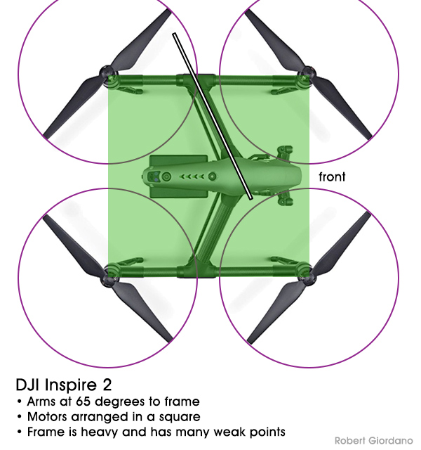
Hybrid H Frame

Now that we’ve seen the pros and cons of the X and H, lets compromise and have it all. Setting the arms at 60 degrees allows the body to be shortened by 60%. Right away you have a body that’s 60% lighter than the H, assuming they’re both made from the same materials. Also, torsional stiffness increases linearly as length decreases. A body that’s 60% shorter is 60% stiffer!

The arms of the Hybrid H will be longer than the H but still shorter than the X. If you really want to know the difference, we can use h/SIN(a) where h=the length of the H frame arm, and a=the arm angle. So, for our 212mm H arms, the X arms would be 300mm (212 / SIN(45) = 299.8) and the Hybrid H arms would only be 245mm (212 / SIN(60) = 244.7). Math is fun right?

So now we have a lighter, stiffer “H” that’s still optimized for front mounted cameras. #winning

Torsional Stiffness

Why do we care about this? To be honest, I really don’t know HOW stiff a frame needs to be in torsion, but I do know what happens when it isn’t stiff enough. One of my early projects was to replace the stock frame of a QAV400 with a DIY carbon fiber H frame. My new frame weighed less than a third of the original but it had very little torsional stiffness. It took me months to figure out what was going on, but it was a problem that could not be solved with PIDs alone. I had to make a stiffer frame. Watch this video and you’ll see the problem when I go into the first turn at 0:30:

Three months later, I built a test stand to measure the torsional stiffness of various frames. In the following video, you’ll see the original QAV400 frame, then my replacement frame, flown in the video above. The original QAV400 isn’t very stiff but my H frame was much worse! Next, I test a few experimental designs for future H frames. At the end of the video is a summary screen:

If you want to know more about torsional stiffness and how its calculated, there’s a great article here: https://www.fictiv.com/hwg/design/design-methods-to-improve-torsional-rigidity

Monocoque Frames

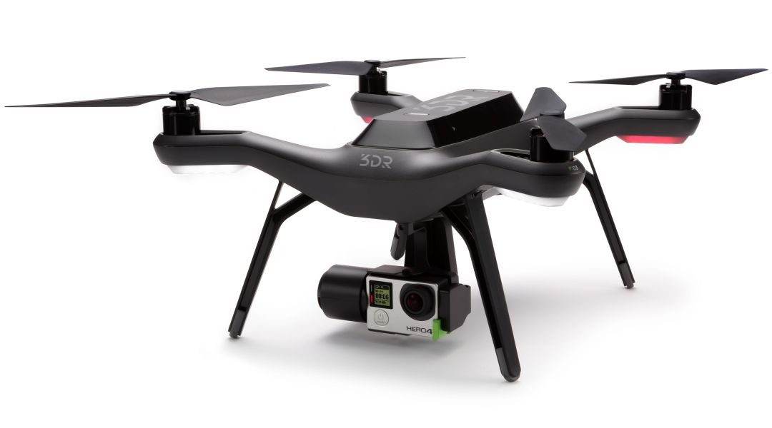
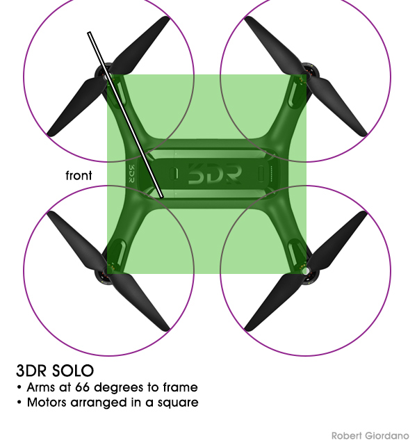
Finally, I wanted to close today’s episode with a bit about monocoque frames since @lucamax mentioned his. A monocoque frame uses the skin or outer shell as its main component. The interior is hollow so it can be filled with payload. Instead of separate arms, plates, brackets, and spacers all bolted together, the arms and body are part of a single piece (or a top and bottom half). A good example of a monocoque frame is the 3DR SOLO. The entire frame is injection molded plastic. It provides a lightweight, smooth, and aerodynamic shape with compound curves. Its hard to beat the weight and strength of a well designed monocoque frame.

But, like most DIY builders, I don’t have the money or resources to create a custom mold and then lay down carbon fiber and resin. I certainly can’t afford a production run of injection molded monocoque frames. That’s why this blog is about building a better quadcopter frame using materials that most of us can afford and access.

One disadvantage of a monocoque frame like the 3DR SOLO is that if you crash and break an arm, you’ll most likely have to replace the entire shell. One of my goals, as stated earlier, is to design a frame that’s crash resistant as well as one that’s easily repaired.

3 Likes

Like this one :

The plastic arms are heavy , they would not be my choice :slight_smile:

1 Like

So what’s solution for a good frame without building it from scratch ?

1 Like

I think it depends on what you want to do with your drone. The Drotek drone you mentioned is not bad. They claim it flies for 50 minutes on a 6S 6000mAh battery. But, that’s with no camera or payload. You could easily add a small FPV camera and transmitter and still get 40 minutes of flight time. But I want a 3D gimbal with a GoPro or heavier camera, plus an FPV camera. I want to fly for 40 minutes and I don’t want to see props in my video.

This thread is about designing and building a better frame. Follow my upcoming posts and I will cover some of the best frames currently available. I’ll talk about their pros and cons. Eventually I want a frame that I don’t have to build from scratch. That’s why I’ll be sharing my plans and 3D files with the community. I’d be happy to see my frame mass produced so I could just buy the parts already cut or printed.

2 Likes

03 - Prototype Frame Outline

(each main blog post has a number and title to set it apart from replies and comments)

Here is the rough layout of my new frame. This is an upgrade from my Drogon V1 frame so I’ll be using the same motors, props, and most of the other components. I’ve decided on a Hybrid-H with the arms at 60 degrees. I’ve also decided to use a square (symmetrical) motor layout. I may decide to do something different in the future but I want to start with the basics. More on that later.

I’ve included a GoPro with 120 and 96 degree field of view (FOV) indicators. This will help me figure out how long the frame body needs to be. In this drawing, the GoPro is level with the props. If I lower it, I can move it back further. But, the more I lower the camera, the longer the landing gear will need to be. I’ll be looking for the best trade off between the two.

Now that I know the motor spacing and the length of the arms, I can start figuring out how I want to build the frame body. I’ll be exploring a number of different options and different materials. I will most likely use carbon fiber plates because they are easily available and fairly easy to cut. I don’t have a CNC machine so my cuts will be limited to simple rectangles. Once I’ve built a successful prototype, I can look into making the pieces lighter with cutouts and easier to assemble with slots and tabs. To do this, the pieces will have to be cut out with a CNC router.

2D vs 3D

I usually start with a 2D program like Photoshop because I can quickly lay out a new frame, move things around, scale objects, and overlay previous designs or third party images. I can print out any part of the design at 1:1 and use the prints to align parts when cutting or gluing them together. If I need to print bigger than 8.5 x 11 (or A4), I can take a thumb drive down the street to FedEx Office and they have a self service printer that can make 24" x 36" prints for $3.

Once I’ve decided on the overall dimensions, I’ll start laying it out in Blender. I use Blender for 3D rendering
because its free, open source, and it runs fairly well on my 2012 Macbook Pro. For more info, visit https://www.blender.org/

Square Layouts vs Other Shapes

I’ve been looking at other commercially produced drone designs to see if I could learn anything from them. Here are a few examples:

Here’s the 3DR SOLO, a Hybrid-H frame (as opposed to an X like the DJI Phantom drones). The arms are at 66 degrees, which is a bit steeper angle than my 60. This makes the arms slightly shorter but also increases the length of the body. But the SOLO uses a monocoque shell design, which saves weight. The motors are spaced in a square, with the same distance left to right as front to rear.

…

The DJI Inspire 2 has an interesting layout. It does a neat trick where the motor arms raise up during flight, moving the landing gear out of the way. I’m still trying to figure out why they did that instead of just having retractable landing gear. I’d also like to know why the two main arms are at 65 degrees to the body instead of a straight 90. This makes the main arms longer and heavier. What’s the advantage?

The Inspire 2 is really heavy. It weighs 3440g with NO camera/gimbal!! The AUW with an X4S is 3693g! I’m still trying to figure out how it can fly for 25 minutes (specs say 27 minutes, but most people report 25 with the X4S). In crashes, it has many weak points. Just do a Google image search for “inspire 2 crash” and you’ll see the arms break either at the motor mount or where the main arm connects to the body.

…

In many respects, I think the Mavic Pro is a better drone than the Inspire 2, and I’m ignoring the difference in price. The Mavic has an incredibly stable hover and is also very nimble. The frame is a Hybrid-H but its motors are NOT square and the the front and rear arms use different angles.

Obviously some thought was put into this and I want to learn from it. I’m still going to build my next prototype with a square motor layout, but I may change this in future designs and it will be nice to have a baseline for comparison.

1 Like

not crashed in 6 years :slightly_smiling_face:

1 Like

Hi, this is really interesting. I had no idea the Inspire was so heavy!

Check out a similar project here that @cglusky produced:
https://discuss.ardupilot.org/t/dev-frame-development-part-2/20220/14
He’s currently doing final testing on a smaller 300 size frame with no inserts, just 3d printed bits, standard CF tubes and some screws.

I’ve flown a 450-ish size first draft of the dev frame and crashed it several times at speed against a stone wall and it’s come off really well! The interesting thing about this design is that you can change the arms to H or X by changing the angle of the blocks that the arms go into. It was designed for maximum payload size - you can fill the top and bottom rails with whatever equipment you like, unlike for example the Drotek frame linked above which has miniscule space for payload.

I really like the idea of 3d printed frames using standard off the shelf parts. Decent quality CF tubes are hard to break, so most crash damage is props or just 3d print replacement frame parts. I don’t have a 3d printer but got the bits printed next day for local pickup super cheap through https://www.3dhubs.com/.

Anyway, didn’t mean to hijack this, but maybe worth combining efforts rather than reinventing the wheel in a different way? Gitter chat is here: https://gitter.im/goodrobots/dev

2 Likes

Hi @fnoop thanks for the link to @cglusky’s project! I’m going to reach out to see if we can collaborate. This blog is more about design, theory, and testing. I’m trying to make it educational. I haven’t seen much data comparing different frame types for weight, stiffness, and performance so I’m trying to fill that void.

For example, its more complicated than just changing the angle of the arms from H to X. A true “X” frame has arms that are joined in the center. By doing so, issues with torsional stiffness are eliminated. If your arms are joined to a frame body, it doesn’t matter if they’re at 90 (H) or 45 (X) degrees. Torsional stiffness in both cases will depend on the stiffness of the frame body.

In upcoming posts, I’ll be comparing some commercially available frames with some of my scratch built frames. For example, I just bought an Alien 680 frame that I’m going to put together and test. I’d love to test one of @cglusky’s frames.

1 Like

@rob215x glad to help if I can but not sure the Dev Frame will be big enough for your needs. It started out that way but we have since decided to focus on 300-500mm builds to keep costs down and simplicity up.

DevFrame is just a simple truss. I have called it a box beam in the past. Technically I guess it could be a Vierendeel truss. It is very rigid at the sizes and loads we use. I did start with a larger version and it was plenty strong. Structural analysis aside, DevFrame is more about trying to find the simplest way to provide an easy to build and maintain frame from 3D printed parts and off the shelf components than any desire to build the strongest frame per weight. For example, the latest design uses # 6 sheet metal screws which are bigger than what is required. But they are also easy to find in about any hardware store on the planet. No free lunch when it comes to considering the total context of a particular use case.

BTW, I think you will find the arm angles of the inspire and other designs you have been analyzing are

  1. Keep out of camera FOV
  2. Set longitudinal CG
  3. Make it all work together. E.g. arm folding

That’s just a guess, but I bet it’s close.

1 Like

Robert , I think that you are looking at the problem in a too much complex point of view.
Between “better” and “perfect” there is a huge difference.

As I wrote the best solution is a monocoque carbon frame but it is also the most expensive.

There are basically only two real important features for a quad frame of a certain dimension class.

  • weight
  • torsional rigidity

These two elements will determine how long and how well will fly our quad but there is also another important feature for a quad if you want to shoot videos and it is the natural frequency of the frame.

If the frequency of your power system will match the natural frequency of your frame then the system will go in resonance and you will have a perfect vibrations generator.

Generally anything printed with a 3D printer is not good for a quad frame because of weak material .
It is by far better if you have a friend with a CNC mill

1 Like

As I wrote before I deign my own frames since 2009.

One of the best frame was developed to solve the problem of vibrations during video shooting.
The result was an extremely rigid frame quite resistant to crashes and simple to build with my CNC mill.

The design is based on the dual center plates design from Mikrokopter but in this case the parts are glued with epoxy, less weight , because no bolts and more rigidity .
Arms were insert into the cuts in the center plates and glued with epoxy, same for motors mounts.

At that time, arms were made with a glass fiber tubes from cheap Chinese fishing rods but of course you can use carbon tubes or square carbon tubes and avoid motor mounts that generally broke when crashing.

gkrellShoot_12-04-2018_044610

Plates were made in fiberglass plates , today I would go for carbon since it is much cheaper than 9 years ago when the frame was designed.

Of course it could have been more light as design but it is just to discuss and give some inspiration .
I threw away that frame , with green Robbe motors from Mikrokopter last week…

1 Like

@lucamax I think you are correct about carbon fiber and a mill if you are building a frame for a specific mission. According to what @rob215x listed in the original post he is trying to abstract the frame for more general use in the DIY crowd.

And I have seen one of my 7Kg all up weight 3D printed designs take an 8G “landing” with nothing more than a broken carbon fiber landing gear tube. If you design to the strengths of the particular material (ABS in my case) and reinforce the printed parts with carbon fiber spars in the right places it works just fine. Not as good as molded carbon fiber but a lot more approachable from a small shop’s manufacturing standpoint.

@rob215x FWIW, I started the Dev Frame in the same size class and the feedback I got from those interested like @fnoop is 300-500 class is better for most dev work since it’s smaller/lighter/cheaper, and not as dangerous when your code turns out to be not as well tested as you thought. Flight time was not as high a priority as protected gear. I don’t do things like house of quality but it might not hurt for a project like this to formally channel the feedback into proper design requirements.

I would love for us to get more feedback. And I can clean up my 700 class frame design, print and send you the parts if you are interested. The biggest differences with the larger version are: It does use threaded inserts vs just screws into plastic, the parts are a bit bigger to handle higher loads, tube spacing is not 60mm, and it does not use metric tubes as I source my larger roll wrapped tubes in the US. Overall, it makes a nice frame with lots of room but it is not as easy to source the parts, and not as approachable for most software devs. Might take me a few weeks since the DevFrame at 300-500 has priority. Just let me know.

BTW, I am @cglusky. Seem to have a couple accounts around this place.

2 Likes