Building a Better Quad Frame

05 - Don’t Believe The Hype

I’m really excited to bring you my next post but its not quite ready yet. It will have a LOT of information and some test results that made me happy today. There will be photos and a short video.

But first, I wanted to respond to several comments about commercially available frames. I’m not here to put anyone down and many companies have spent ridiculous amounts of money to bring their products to market. Of course everyone is going to say THEIR drone or drone frame is the best thing since French Toast (and if you don’t like French Toast, I’m very, very sorry)

I don’t believe anything until I see it for myself. I don’t believe battery ratings. I don’t believe advertised flight times, and I don’t even believe published weights. (I weigh everything with two different scales). Finally, I don’t even believe my own hype. I’ll design something that looks great to me on paper but comes apart when I begin the stress tests. The new frame I’ll be showing you later tonight or tomorrow, is version 2.4.6. That means v2.1, v2.2, and v2.3 failed at least one of my tests (weight being one of them).

This photo proves that you can put motors and props on almost ANYTHING and Ardupilot will fly it!! This was an experiment I tried several years ago with APM 2.5 and it floats in a swimming pool! But, just because it can fly, doesn’t mean its going to fly well… or fly more than twice, lol.

I’m not a vendor. I don’t have a new drone on Kickstarter (there’s a new one every week right?) I’m here to cut through the BS and share what I’ve learned so we can all start building better frames. Yes, you can build lighter, stronger, and cheaper frames, with easy to find materials and just a few basic tools. My next post will prove all of this with an example. :sunglasses:

2 Likes

@LuisVale I think the S900 is a horrible frame! It is floppy and not very rigid. Convenient though. A workhorse to be sure.

@Marc_Dornan I have several with hundreds of hours each, with the extended power kit, without issues.

Oh I know they work fine. I have used them quite a bit as well. But as an
engineering piece — me no likey!

Totally agree Rob !
3 years ago, I had a dispute with T-Motor about the performance they claim for one of their motors, the tested performance was from 18,2% to 8,2% less than T-Motor specs even using the same Esc and propeller they did, finally they gave no explanation or apologize for lying.
Another motor vendor won the hoax first place plotting their performance data on a XY graph where the X axis had a “variable” interval for values , so the plotted curve was nicer :open_mouth:

2 Likes

06 - Prototype Frame v2.4.7

Okay, here we go. This is the first in a series of frames that will hopefully improve as this blog continues.

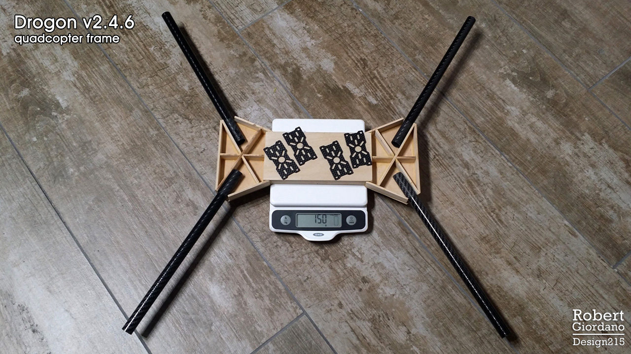
You might notice the picture says v2.4.6 while the title of this post says v2.4.7. That’s because I just made some improvements to the design, based on my tests. I’ll be posting the complete v2.4.7 design below. By the way, the frame is on the scale upside down. You are looking at the bottom :wink:

What is This Thing?

This is NOT a final product! This is a quadcopter frame that is light, stiff, cheap, and easy to build. Its has the following specs:

  • It weighs 150g as pictured (174g with complete motor mount hardware).
  • Its has a 680mm wheelbase optimized for 15" props, with clearance for 16" props.
  • It is torsionally stiffer than many similar sized commercial frames (more on that below).

This is meant to be a very general purpose frame. You could hang a camera or gimbal underneath and put legs on it. You could add extension tubes and have a front mounted gimbal that clears the props. You could do something in-between. It is designed to be easily scaled to other size classes. It can also be modified for different diameter arms by changing one parameter.

Why Did You Use Wood?

I use birch plywood and basswood for all of my prototypes because:

  • Its cheap. For $30, I have enough wood to build 3 frames.
  • Local arts and crafts stores have it in stock.
  • Its easy to cut.
  • Its easy to glue.

Once the wood version passes all of my tests, I can build it again with all carbon fiber and have something even lighter and stiffer.

How Stiff is This Frame?

While the birch plywood I used for this frame isn’t as stiff as carbon fiber, its better than most H Frames I’ve tested. I just made this short video comparing my Drogon v1 “X” frame, an H4 Alien 680mm frame, and my v2.4.6 wood frame:

a few points about the video:

  • A true X frame (where the arms are continuous) has no problems with torsional stiffness. That’s just how an X works. When you separate the arms in the center and join them with top and bottom plates, you don’t have a true X anymore. But, you can’t run wires through continuous arms.
  • My wood frame is almost twice as stiff as the Alien 680 frame. You can grab the front and back of the Alien 680 frame body and twist it with your hands. You can’t do that with my wood frame.
  • Even though v2.4.6 is fairly stiff, its not as stiff as it could be. Yes, if it was built from all carbon fiber, it should be stiffer. But I made some slight design changes in v2.4.7 that I think will make it even better. I’ll list the details below.

Cheap and Easy to Build

Besides weight and stiffness, I consider a few other factors when I’m designing a frame for this blog. How expensive is it going to be? Are the materials easily available? What kinds of tools are necessary. For a DIY community, I think these factors are just as important as any others.

I live in a fairly small apartment. I have no garage. I have no workshop. I have an assigned parking space. I build most things on my living room floor. I have a nice collection of basic tools but I don’t have a 3D printer, or a CNC router, or anything fancy.

I built the whole frame in a day. I went to Michael’s Arts and Crafts and spent $29.55 on two pieces of birch plywood (1/8" and 1/16"). I went to Home Depot and got some Titebond II Premium Wood Glue and some JB Weld Clearweld Epoxy (the epoxy is for attaching the carbon fiber tubes to the wood frame body). I used one electric saw to cut all of my wood and carbon fiber. Its a Rockwell BladeRunner X2 that I got on Amazon for $100. I’ve had it for 3 years now and I love it. I used a sanding block, and some emery nail files from the beauty supply store. The next day it was ready for stress testing. It took me longer to create this post (including shooting and editing the video) than it did to build the frame, lol.

The Design, v2.4.7


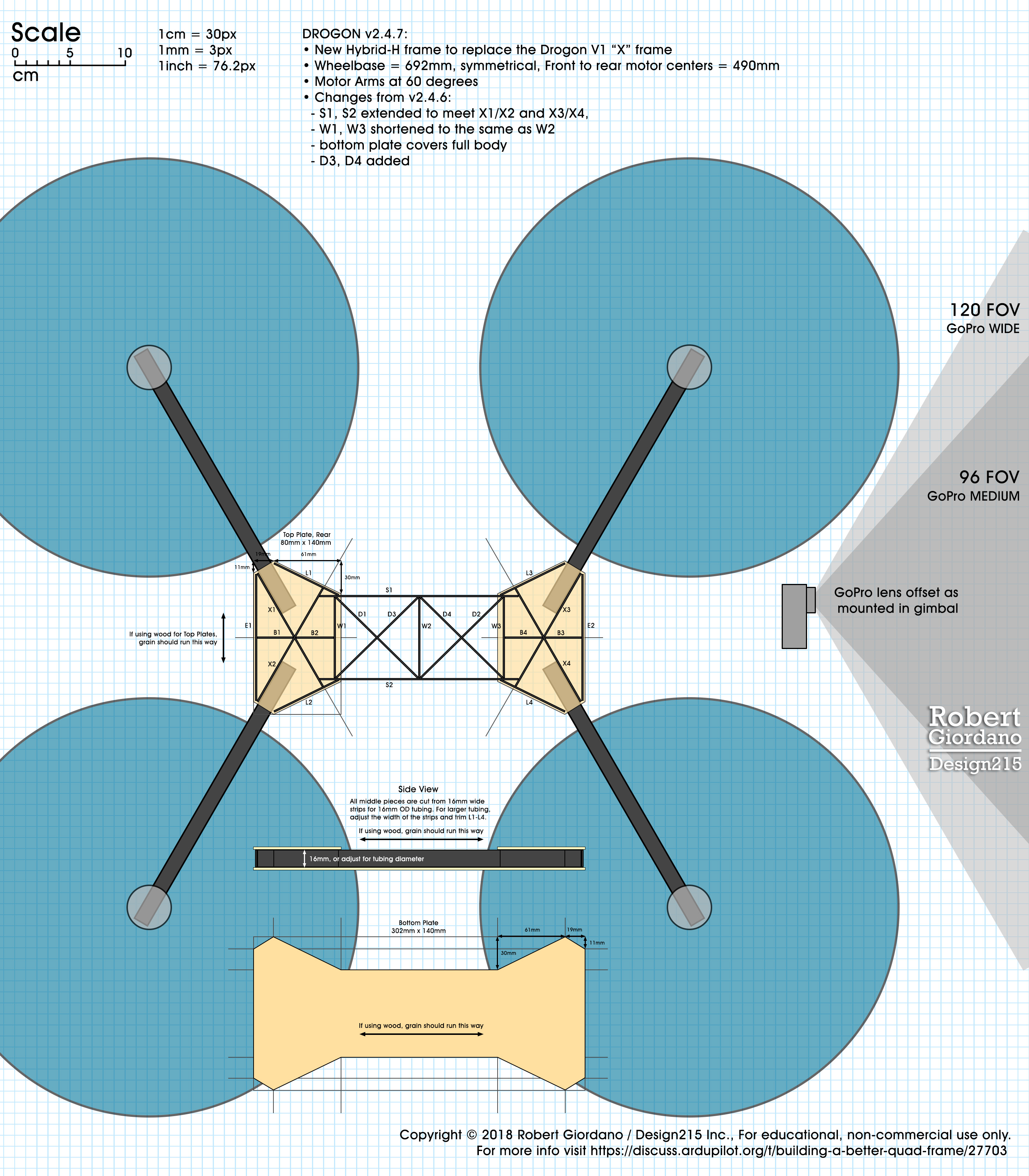
(Click the image to download the full size drawing from Dropbox)

I make these drawings to be printed at 100% scale. When printed properly, you can put a centimeter ruler on it and the grid lines will be exactly 1cm squares. I put the JPG file on a thumb drive and I go down the street to FedEx Office. They have a printer that lets me make 24" x 36" monochrome prints for $3. Back at home, I use the drawings as templates to align and glue the pieces together. I use the guides on the drawing to mark where I’m going to cut the pieces.

Changes from 2.4.6 to 2.4.7

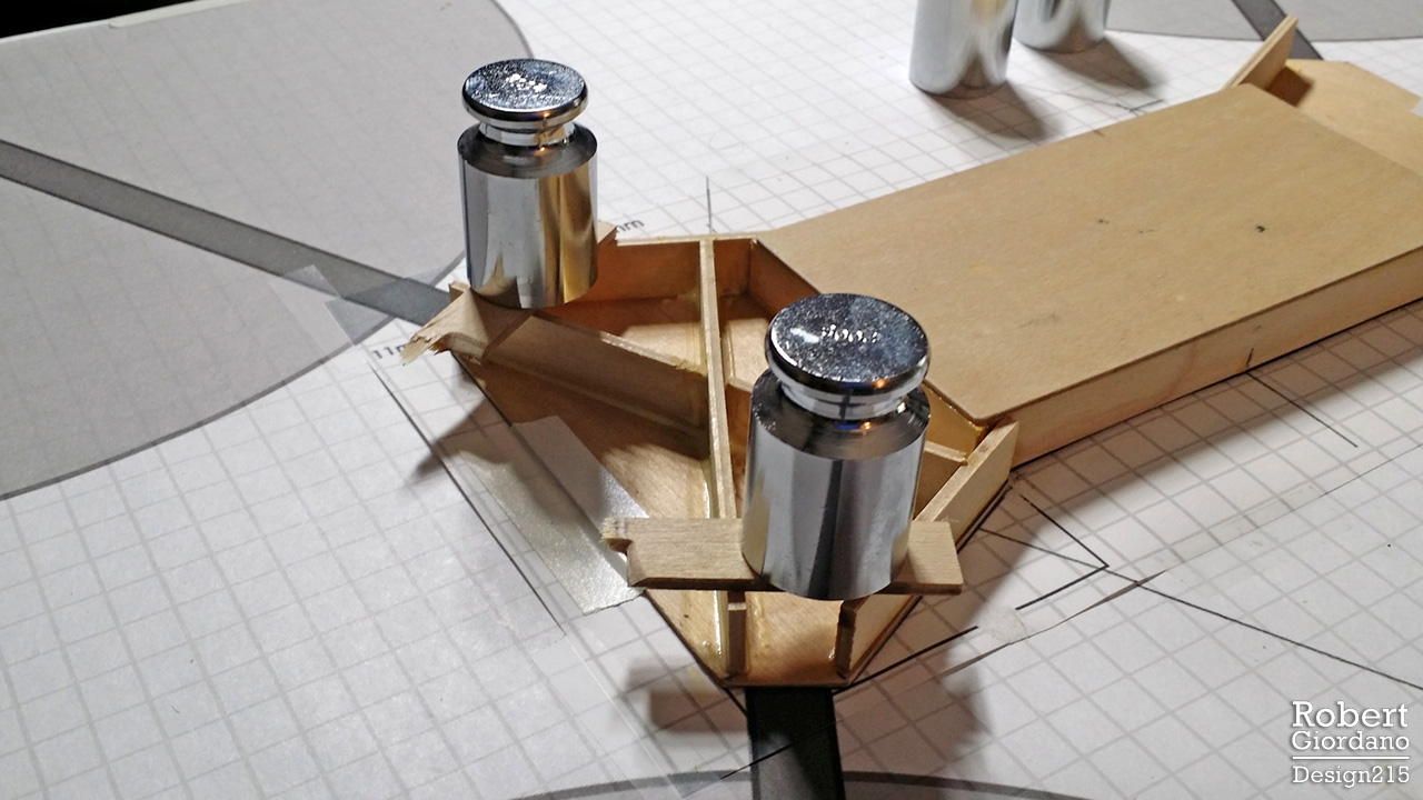
The frame is upside down in the first picture and torsion tests. The middle is open at the top and the ends are open underneath. I did this mainly to save weight, although I also wanted access to the wiring from the motors as it comes out of the tube ends. The middle section is open on the top for similar reasons but I’ll get into that in another post. In 2.4.7, the bottom plate now covers the entire frame body. I believe the advantages outweigh the savings of a few grams. I’ll just have to be more precise when I cut holes in the top plates for the motor wires.

Next, I found weak points where S1 and S2 ended at W1 and W3, forming the corners of a box. By extending S1 and S2 so they meet X1/X2 and X3/X4, it will create a stronger frame that should be stiffer as well.

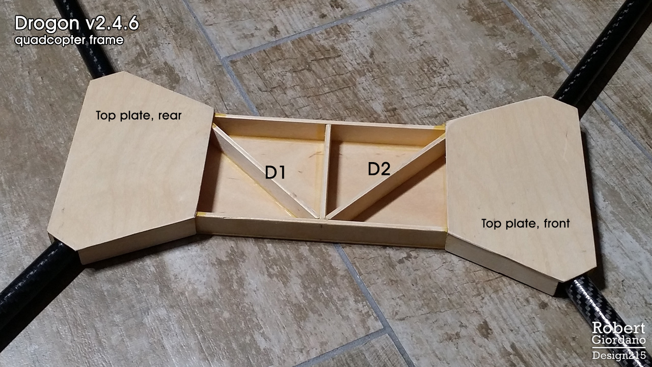
Finally, the frame I tested in the video only has D1 and D2. I may or may not add D3 and D4 as I’m going to test it with the first two modifications before I add the extra diagonal braces. Since the middle section will remain open at the top, I can add D3 and D4 later.

A Note About X1/X2 and X3/X4

I should probably add a note about this in the drawing itself, but X1, X2, X3, X4 are continuous pieces with notches so they interlock. Each one is 118mm long. The notch is NOT is the middle so its best to cut the pieces and then use the drawing to mark where the notches go. This is where I use the emery fingernail files to angle the notches until both pieces fit together nicely and sit at the properly angle without having to hold them.

If I decide to add D3 and D4, they will also be notched so they interlock with D1 and D2.

Copyright?

My intention is to post these drawings and plans for everyone to use freely. At the same time, I want to keep my name on them and I don’t want them used commercially without my permission. I’m thinking its the same as my photography, where I can post my photos on social media and everyone can share them, even though I still retain my copyright. If anyone has suggestions, feel free to DM me.

That’s all for tonight. I have a LOT more coming! :sunglasses:

2 Likes

Going over your design I think your camera is a little forward. Also I like to see the integrating of the gimbals rails into the basic layout of the frame and legs connections. +1 for wooden prototypes and spruce.

1 Like

Very cool I like the odd designs.

1 Like

I will make a future post about camera positioning. The camera is there now mainly for scale and to show field of view relative to the props. I will also make a post about legs. I have some really lightweight designs that work well.

Since this is a general purpose frame, you could mount a camera or gimbal underneath, on top, or out in front. That’s why I don’t have gimbal rails in the design. In a future design I will probably do that.

Nice frame. Do you plan to place in any kind of folding mechanism for rays?

1 Like

Thank you. I really like the H4 Alien 680 frame because it has folding arms. I don’t like it because it is heavy and is not very stiff. I may try to use its folding mechanism in a new frame. If you eliminate the brackets for locking the arms closed and only use the brackets for locking the arms open, the components for all 4 arms weighs 54g.

This will require removing some inner plates for moving rays and lead to decrease of torsion stiffness. That is the place where i’ve stacked with my design of similar frame.

I think JoHannes has done similar work and his super lightweight, efficient designs still do real work. He uses carbon sandwich materials for stiffness and light weight and keeps the design simple. The design is easily reproduced by shops that offer cnc cutting of carbon at very reasonable costs and it folds.

https://translate.googleusercontent.com/translate_c?depth=1&hl=en&ie=UTF8&prev=_t&rurl=translate.google.com&sl=auto&sp=nmt4&tl=en&u=http://der-frickler.net/start&xid=17259,15700022,15700124,15700149,15700168,15700173,15700186,15700201&usg=ALkJrhi4RjgCF5vHCCetYZ1-Va42ss2UmQ

2 Likes

Thanks Mike, this looks like a good example of an efficient design:

  • Hydrid H frame with a shortened body to save weight.
  • The motors seem to be in a square layout (hard to tell from the photo angle).
  • The front arms are >60 degrees while the rear arms are <60 degrees, which shifts the body forward so the camera’s field of view clears the props.
  • There’s no landing gear, which also saves weight and increases flight time.

I like that the arms fold and the layout is very clean and simple. There are two things I cannot tell from the picture. How much does the frame weigh? How stiff is it in torsion?

I’m aware of materials like carbon/balsa sandwich, carbon/birch sandwich, and other hybrid materials. For now, I’ve stayed away from those materials because they tend to be expensive and more difficult to obtain. I’m trying to see what a person can achieve with local or easily available materials, and no special tools.

I’m guessing the square tubing works better for folding arms, and while it isn’t as aerodynamic as round tubing, it probably doesn’t make a noticeable difference in this ship’s overall flight performance.

It looks like the whole AUW is 2050g from his website. I think the square arms really help in stiffness compared to round arms. I think it is great that you are looking for a solution with readily available materials. He uses carbon/foam laminate.

I used the basic ideas on my recent Solo conversion project with junk box parts and I am sold. I am getting some custom plates done by CNC Madness out of carbon/foam to do it right.
https://www.rcgroups.com/forums/showthread.php?2987934-The-cleanest-simplest-Arducopter-build-ever
Best of Luck

1 Like

07 - Square Tubing vs Round Tubing

I wasn’t sure when I was going to talk about this but I might as well do it now. You love math right?

The thing is, he’s not wrong but there’s a lot more to this story. I think it really helps to understand what’s going on so we can all make the best decisions when designing and building our own frames. I heard this debate all the time as a welder. There are times to use square tubing and times to use round tubing. I made the following graphic to simplify this concept:

So, Mike is right if you compare 16mm square tubing to 16mm OD round tubing, both made from the same material and both with 1.0mm wall thickness. The 16mm round tube is only 59% as strong as the square tubing. BUT, the round tube is 22% LIGHTER!

The next thing to notice is the 20mm round tube on the right. It weighs the same as the square tube but its 20% STRONGER!

Now this doesn’t mean you should always use round tubing. There will be times when the strength of the square tube is more important than the weight savings of the round tube. Going to a larger tube diameter may not always be possible. A larger tube will be more expensive and may require heavier motor mounts.

I hope this helps everyone. If you like my graphic, please feel free to share it anywhere!

Math

  • Cross section area, round tube: PI/4 (OD2 - ID2)
    for 16mm tubing its 3.1415/4(162-142) = 47.12mm2

  • Cross section area, square tube: OD2 - ID2
    that’s just the outer square minus the inner square, 256-196 = 60mm2

  • Moment of inertia, round tube: PI/64 (OD4 - ID4)
    for 16mm round tubing its 3.1415/64(164-144) = 1331mm4

  • Moment of inertia, square tube: 1/12 (OD4 - ID4)
    for the 16mm square tube its 0.08333(164-144) = 2260mm4

Sources

The first two links are online calculators:
http://www.amesweb.info/SectionalPropertiesTabs/SectionalPropertiesHollowCircle.aspx
http://www.amesweb.info/SectionalPropertiesTabs/SectionalPropertiesHollowRectangle.aspx

http://mnhpva.org/tech/frame_tubes.html
https://www.engineeringtoolbox.com/pipe-formulas-d_1335.html
https://en.wikipedia.org/wiki/Moment_of_inertia
https://en.wikipedia.org/wiki/Polar_moment_of_inertia

2 Likes

Sure round will always be stronger BUT this is applied math/physics not theory and the mitigating factor is the horrible mounting mechanism for round tubing. The plastic pivot joints and the typical “C” clamps, at least for folding frames, are flexy, heavy and not strong at all.

With square tubing you don’t need any of that. Because it is flat it is like a box frame inside the main plates making it stronger, without anything but a couple of screws to hold it in place. It is a stronger, stiffer attachment and the overall weight is much less.

Now it is a little different at the other end simply because there are few motor mounts made for square tubing.

4 Likes

I agree with all of that. My chart shows that 16mm square is 41% stronger than 16mm round and only 22% heavier. The extra weight is canceled by eliminating those brackets and c-clamps you mentioned. :grinning:

You could also run the numbers the other way and use smaller square tubing…

My next post is about motor mounts. Hopefully it will help you. :grinning:

08 - Motor Mounts… Please Help!

I’ve looked at quite a few motor mounts and I’ve done a number of experiments. We really need more choices in this department. I have some ideas but I don’t have a 3D printer. I know some of you do, and hopefully we can work together. At the end of this post I think I’ve found a good solution, but let’s see how I got there…

This is what I found on the internet for 16mm round tubing. I selected 16mm because it seems to be the most popular. One of the problems I face is, I don’t see many choices if I want to use 18mm or 20mm tubing. Most of the mounts I saw were variations on one of these five. They’re sorted by weight.

OMG, Those mounts are HEAVY!

I designed and built a 680mm frame that only weighs 140g and now I need to add another 100g just for motor mounts? No thanks.

Mount D

I like this style mount because you can use it for an X8 and if you’re only building a quad, you can leave off one of the motor plates. One plate and 4 screws is usually 3-4 grams so 16x4 = 64g isn’t so bad. But it’s not light enough for me.

Mount E

Even though this mount is lighter, I don’t like it. You can’t use it for an X8 and in a crash, it will be weaker than Mount D. Mounts B, C, and E all have a weak point where the tube connector meets the motor plate. Even the Tarot mount has a similar weak point. Look at how little material there is between the tube connector and the motor plate. A heavy motor attached to that plate will act as a lever and guess where its gonna break?

EDIT 2018/04/26: This paragraph is about Mount E and I should have used the picture of Mount E instead of the following picture of the Tarot mount because; a) I haven’t used the Tarot mount myself, and b) According to the community, the Tarot mount is pretty strong. That being said, everyone agrees the Tarot mount is heavy and I do have lighter solutions that are just as strong if not stronger.

failure-points

3D Printed Mounts

My previous ship used 3D printed motor mounts. They were designed and printed by a friend in another group. He made several sets of them and they are quite excellent:

Each mount is glued to the tube with epoxy. Because they are glued together over the surface of the tube, they strengthen each other as one solid piece. Each mount AND the epoxy weighs 8g, for a total of 32g!

So, what’s the downside?

  • They were designed for a very specific, 15.26mm OD tubing. Yes, I might be able to modify the 3D file and have them printed for 16mm tubing, but then I wouldn’t have clearance for the bolts that go into the motor.
  • They won’t work for motors with a different bolt pattern.
  • They won’t work for an X8.

So, I want to make something different. But these 3D printed mounts have certainly set the bar on weight and strength!

Recent Experiments

I’ve been playing with the motor mounts that came with my H4 Alien 680mm frame. They are very similar to mount D above. They can be used for a quad or an X8. I like the separate carbon fiber motor plates because they allow for a variety of motor sizes and bolt patterns, and they can be changed if they break.

At 20g each, that’s 80g added to my frame instead of 32g for the 3D printed mounts. Let’s see what we can do with these Alien680 mounts…

Here’s all four mounts with one motor plate removed and the four screws for each plate. Now each mount weighs 15.5g. But I’m not done…

Now each mount weighs 11.7g! All I did here was switch to nylon bolts. I’ve been using nylon bolts for years and I’ve never had a problem. But I know what you’re thinking-- I won’t be able to tighten the nylon bolts enough to clamp the mount to the tube. You’re right! And, I’m not going to use the bolts to clamp the mounts to the tube. I’ll use a little epoxy between the red halves and the tube. I will never have to worry about my motor mounts rotating out of square. The nylon bolts will simply hold the motor plates. I can take the motor plates on and off without having to level the mounts each time.

Can I go further? Hmmm…

Here I am at 32g, the same as my 3D printed mounts! But wait, I don’t like it. Now I only have half the surface area to epoxy to the tubing and I don’t have the safety of the nylon bolts. Even though the bolts aren’t clamping the mount to the tube, they still go through both halves, making a solid ring around the tube. The bolts pass through one half with no threads, into the other half that’s threaded all the way through. So far, the 46g solution looks the best.

But what if…

What if I used the lighter halves of the red tube clamp (the ones with no threads) and cut some pieces of carbon fiber plate (10mm x 32mm x 2mm) for the bottom side of the tube? The answer is 8.8g each, or 35.2g total! And, now I have some safety once again because the mounts are held on by epoxy and by the nylon bolts running through my carbon fiber plates on the other side of the tube. If I want to change it to X8, I can just use the other halves of the tube clamps and I’ll be back to the 46g configuration.

If you’re worried about the nylon nuts coming loose, use a little CA glue. If you need to remove them, you can cut the nylon bolts like you would a zip tie. Personally, I don’t worry about nylon bolts coming loose. They are naturally self-locking. I’ll probably do a separate post just on nylon bolts.

What about square tubing?

Well, I’ve been thinking more and more about square tubing. As it turns out, the previous solution works even better for square tubing…

There you go! 6.5g each and only 26g total! All I did here was replace the aluminum tube brackets with 10mm x 32mm pieces of 1/8" birch plywood. Sorry I didn’t drill holes for the picture but you would run the bolts through the wood, which just acts as a spacer for the motor shaft and its bolts. The mount bolts continue though the carbon fiber plates on the underside of the square tubing. The wood spacers are easily epoxied to the tube because both surfaces are flat. If you’re only building a quad, I would epoxy the carbon fiber plates as well.

Here’s where I need your help…

Looking at all of this, I think a great solution would be 3D printed “rings” that are similar in size as the red aluminum tube clamps. But instead of each side being two halves, each side would be single “ring” that slides over the tube and is epoxied in place. The rings don’t need threads, just a hole on each side. Bolts would run through the rings, then through the motor mount plate, and secured with nuts. The carbon fiber plates on the bottom are no longer needed.

Rings could be printed for different sizes of tubing, including square. If you’re building an X8, you would just add a second motor plate.

If any of you would like to help me make some of these, please let me know. I don’t have a 3D printer and I don’t have any of the software people use to print things. I can create nice looking 3D models in Blender if that helps. I think this system could work really well. It would be stronger and SO much lighter than anything else I’ve seen!

Where do I get nylon bolts?

Local hardware stores have them but you’ll pay a lot. The best place I’ve found is McMaster-Carr. Here’s an example: Nylon M3 x 0.5mm thread, 20mm long, black, $7.87 for a pack of 100.