Building a Better Quad Frame

You’re right the lightest the better, but we can do some simple maths about it.
Frame/mtom could be a parameter, also frame/payload…
Frame : 3kg for the 1400mm
Max Useful Load : 40kg/88lbs

I do not believe everything that it is written in the specs of vendors.
How many people needs 40 kg of payload ?
In a lot of countries over 25 kg AUW , it is not simple to comply UAV rules.

Finally if I had to lift 40 kg of payload I would not certainly use a multirotor.

2 Likes

Thanks fnoop. I am looking for something that can carry 1.5kg - gimbal, camera, lidar.

S800 (old) or S900 frame if wanting to go ready to run frame+esc+motors

Like any design it’s all about compromise. Design without compromise has a name - it’s called Art. In the real world of functional devices we are forced to balance many things.

If you are very honest about your requirements and work backwards I think you can find a frame to meet your needs. But it has to be requirements in context - fiscal, technical, operational, logistical - it all matters. After all, if one size did fit all then the DJI would have met your needs as they do make nice systems.

1 Like

05 - Don’t Believe The Hype

I’m really excited to bring you my next post but its not quite ready yet. It will have a LOT of information and some test results that made me happy today. There will be photos and a short video.

But first, I wanted to respond to several comments about commercially available frames. I’m not here to put anyone down and many companies have spent ridiculous amounts of money to bring their products to market. Of course everyone is going to say THEIR drone or drone frame is the best thing since French Toast (and if you don’t like French Toast, I’m very, very sorry)

I don’t believe anything until I see it for myself. I don’t believe battery ratings. I don’t believe advertised flight times, and I don’t even believe published weights. (I weigh everything with two different scales). Finally, I don’t even believe my own hype. I’ll design something that looks great to me on paper but comes apart when I begin the stress tests. The new frame I’ll be showing you later tonight or tomorrow, is version 2.4.6. That means v2.1, v2.2, and v2.3 failed at least one of my tests (weight being one of them).

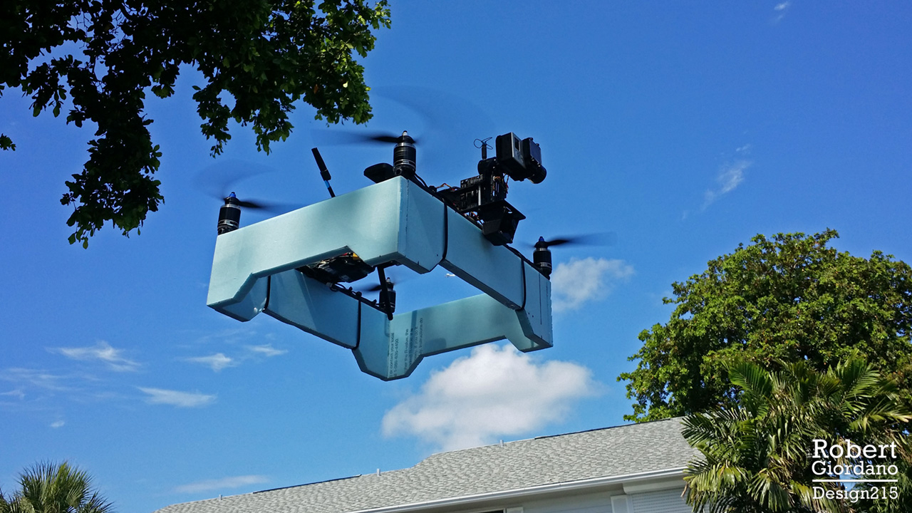
This photo proves that you can put motors and props on almost ANYTHING and Ardupilot will fly it!! This was an experiment I tried several years ago with APM 2.5 and it floats in a swimming pool! But, just because it can fly, doesn’t mean its going to fly well… or fly more than twice, lol.

I’m not a vendor. I don’t have a new drone on Kickstarter (there’s a new one every week right?) I’m here to cut through the BS and share what I’ve learned so we can all start building better frames. Yes, you can build lighter, stronger, and cheaper frames, with easy to find materials and just a few basic tools. My next post will prove all of this with an example. :sunglasses:

2 Likes

@LuisVale I think the S900 is a horrible frame! It is floppy and not very rigid. Convenient though. A workhorse to be sure.

@Marc_Dornan I have several with hundreds of hours each, with the extended power kit, without issues.

Oh I know they work fine. I have used them quite a bit as well. But as an
engineering piece — me no likey!

Totally agree Rob !
3 years ago, I had a dispute with T-Motor about the performance they claim for one of their motors, the tested performance was from 18,2% to 8,2% less than T-Motor specs even using the same Esc and propeller they did, finally they gave no explanation or apologize for lying.
Another motor vendor won the hoax first place plotting their performance data on a XY graph where the X axis had a “variable” interval for values , so the plotted curve was nicer :open_mouth:

2 Likes

06 - Prototype Frame v2.4.7

Okay, here we go. This is the first in a series of frames that will hopefully improve as this blog continues.

You might notice the picture says v2.4.6 while the title of this post says v2.4.7. That’s because I just made some improvements to the design, based on my tests. I’ll be posting the complete v2.4.7 design below. By the way, the frame is on the scale upside down. You are looking at the bottom :wink:

What is This Thing?

This is NOT a final product! This is a quadcopter frame that is light, stiff, cheap, and easy to build. Its has the following specs:

  • It weighs 150g as pictured (174g with complete motor mount hardware).
  • Its has a 680mm wheelbase optimized for 15" props, with clearance for 16" props.
  • It is torsionally stiffer than many similar sized commercial frames (more on that below).

This is meant to be a very general purpose frame. You could hang a camera or gimbal underneath and put legs on it. You could add extension tubes and have a front mounted gimbal that clears the props. You could do something in-between. It is designed to be easily scaled to other size classes. It can also be modified for different diameter arms by changing one parameter.

Why Did You Use Wood?

I use birch plywood and basswood for all of my prototypes because:

  • Its cheap. For $30, I have enough wood to build 3 frames.
  • Local arts and crafts stores have it in stock.
  • Its easy to cut.
  • Its easy to glue.

Once the wood version passes all of my tests, I can build it again with all carbon fiber and have something even lighter and stiffer.

How Stiff is This Frame?

While the birch plywood I used for this frame isn’t as stiff as carbon fiber, its better than most H Frames I’ve tested. I just made this short video comparing my Drogon v1 “X” frame, an H4 Alien 680mm frame, and my v2.4.6 wood frame:

a few points about the video:

  • A true X frame (where the arms are continuous) has no problems with torsional stiffness. That’s just how an X works. When you separate the arms in the center and join them with top and bottom plates, you don’t have a true X anymore. But, you can’t run wires through continuous arms.
  • My wood frame is almost twice as stiff as the Alien 680 frame. You can grab the front and back of the Alien 680 frame body and twist it with your hands. You can’t do that with my wood frame.
  • Even though v2.4.6 is fairly stiff, its not as stiff as it could be. Yes, if it was built from all carbon fiber, it should be stiffer. But I made some slight design changes in v2.4.7 that I think will make it even better. I’ll list the details below.

Cheap and Easy to Build

Besides weight and stiffness, I consider a few other factors when I’m designing a frame for this blog. How expensive is it going to be? Are the materials easily available? What kinds of tools are necessary. For a DIY community, I think these factors are just as important as any others.

I live in a fairly small apartment. I have no garage. I have no workshop. I have an assigned parking space. I build most things on my living room floor. I have a nice collection of basic tools but I don’t have a 3D printer, or a CNC router, or anything fancy.

I built the whole frame in a day. I went to Michael’s Arts and Crafts and spent $29.55 on two pieces of birch plywood (1/8" and 1/16"). I went to Home Depot and got some Titebond II Premium Wood Glue and some JB Weld Clearweld Epoxy (the epoxy is for attaching the carbon fiber tubes to the wood frame body). I used one electric saw to cut all of my wood and carbon fiber. Its a Rockwell BladeRunner X2 that I got on Amazon for $100. I’ve had it for 3 years now and I love it. I used a sanding block, and some emery nail files from the beauty supply store. The next day it was ready for stress testing. It took me longer to create this post (including shooting and editing the video) than it did to build the frame, lol.

The Design, v2.4.7


(Click the image to download the full size drawing from Dropbox)

I make these drawings to be printed at 100% scale. When printed properly, you can put a centimeter ruler on it and the grid lines will be exactly 1cm squares. I put the JPG file on a thumb drive and I go down the street to FedEx Office. They have a printer that lets me make 24" x 36" monochrome prints for $3. Back at home, I use the drawings as templates to align and glue the pieces together. I use the guides on the drawing to mark where I’m going to cut the pieces.

Changes from 2.4.6 to 2.4.7

The frame is upside down in the first picture and torsion tests. The middle is open at the top and the ends are open underneath. I did this mainly to save weight, although I also wanted access to the wiring from the motors as it comes out of the tube ends. The middle section is open on the top for similar reasons but I’ll get into that in another post. In 2.4.7, the bottom plate now covers the entire frame body. I believe the advantages outweigh the savings of a few grams. I’ll just have to be more precise when I cut holes in the top plates for the motor wires.

Next, I found weak points where S1 and S2 ended at W1 and W3, forming the corners of a box. By extending S1 and S2 so they meet X1/X2 and X3/X4, it will create a stronger frame that should be stiffer as well.

Finally, the frame I tested in the video only has D1 and D2. I may or may not add D3 and D4 as I’m going to test it with the first two modifications before I add the extra diagonal braces. Since the middle section will remain open at the top, I can add D3 and D4 later.

A Note About X1/X2 and X3/X4

I should probably add a note about this in the drawing itself, but X1, X2, X3, X4 are continuous pieces with notches so they interlock. Each one is 118mm long. The notch is NOT is the middle so its best to cut the pieces and then use the drawing to mark where the notches go. This is where I use the emery fingernail files to angle the notches until both pieces fit together nicely and sit at the properly angle without having to hold them.

If I decide to add D3 and D4, they will also be notched so they interlock with D1 and D2.

Copyright?

My intention is to post these drawings and plans for everyone to use freely. At the same time, I want to keep my name on them and I don’t want them used commercially without my permission. I’m thinking its the same as my photography, where I can post my photos on social media and everyone can share them, even though I still retain my copyright. If anyone has suggestions, feel free to DM me.

That’s all for tonight. I have a LOT more coming! :sunglasses:

2 Likes

Going over your design I think your camera is a little forward. Also I like to see the integrating of the gimbals rails into the basic layout of the frame and legs connections. +1 for wooden prototypes and spruce.

1 Like

Very cool I like the odd designs.

1 Like

I will make a future post about camera positioning. The camera is there now mainly for scale and to show field of view relative to the props. I will also make a post about legs. I have some really lightweight designs that work well.

Since this is a general purpose frame, you could mount a camera or gimbal underneath, on top, or out in front. That’s why I don’t have gimbal rails in the design. In a future design I will probably do that.

Nice frame. Do you plan to place in any kind of folding mechanism for rays?

1 Like

Thank you. I really like the H4 Alien 680 frame because it has folding arms. I don’t like it because it is heavy and is not very stiff. I may try to use its folding mechanism in a new frame. If you eliminate the brackets for locking the arms closed and only use the brackets for locking the arms open, the components for all 4 arms weighs 54g.

This will require removing some inner plates for moving rays and lead to decrease of torsion stiffness. That is the place where i’ve stacked with my design of similar frame.

I think JoHannes has done similar work and his super lightweight, efficient designs still do real work. He uses carbon sandwich materials for stiffness and light weight and keeps the design simple. The design is easily reproduced by shops that offer cnc cutting of carbon at very reasonable costs and it folds.

https://translate.googleusercontent.com/translate_c?depth=1&hl=en&ie=UTF8&prev=_t&rurl=translate.google.com&sl=auto&sp=nmt4&tl=en&u=http://der-frickler.net/start&xid=17259,15700022,15700124,15700149,15700168,15700173,15700186,15700201&usg=ALkJrhi4RjgCF5vHCCetYZ1-Va42ss2UmQ

2 Likes

Thanks Mike, this looks like a good example of an efficient design:

  • Hydrid H frame with a shortened body to save weight.
  • The motors seem to be in a square layout (hard to tell from the photo angle).
  • The front arms are >60 degrees while the rear arms are <60 degrees, which shifts the body forward so the camera’s field of view clears the props.
  • There’s no landing gear, which also saves weight and increases flight time.

I like that the arms fold and the layout is very clean and simple. There are two things I cannot tell from the picture. How much does the frame weigh? How stiff is it in torsion?

I’m aware of materials like carbon/balsa sandwich, carbon/birch sandwich, and other hybrid materials. For now, I’ve stayed away from those materials because they tend to be expensive and more difficult to obtain. I’m trying to see what a person can achieve with local or easily available materials, and no special tools.

I’m guessing the square tubing works better for folding arms, and while it isn’t as aerodynamic as round tubing, it probably doesn’t make a noticeable difference in this ship’s overall flight performance.

It looks like the whole AUW is 2050g from his website. I think the square arms really help in stiffness compared to round arms. I think it is great that you are looking for a solution with readily available materials. He uses carbon/foam laminate.

I used the basic ideas on my recent Solo conversion project with junk box parts and I am sold. I am getting some custom plates done by CNC Madness out of carbon/foam to do it right.
https://www.rcgroups.com/forums/showthread.php?2987934-The-cleanest-simplest-Arducopter-build-ever
Best of Luck

1 Like