Building a Better Quad Frame

It looks like the whole AUW is 2050g from his website. I think the square arms really help in stiffness compared to round arms. I think it is great that you are looking for a solution with readily available materials. He uses carbon/foam laminate.

I used the basic ideas on my recent Solo conversion project with junk box parts and I am sold. I am getting some custom plates done by CNC Madness out of carbon/foam to do it right.
https://www.rcgroups.com/forums/showthread.php?2987934-The-cleanest-simplest-Arducopter-build-ever
Best of Luck

1 Like

07 - Square Tubing vs Round Tubing

I wasn’t sure when I was going to talk about this but I might as well do it now. You love math right?

The thing is, he’s not wrong but there’s a lot more to this story. I think it really helps to understand what’s going on so we can all make the best decisions when designing and building our own frames. I heard this debate all the time as a welder. There are times to use square tubing and times to use round tubing. I made the following graphic to simplify this concept:

So, Mike is right if you compare 16mm square tubing to 16mm OD round tubing, both made from the same material and both with 1.0mm wall thickness. The 16mm round tube is only 59% as strong as the square tubing. BUT, the round tube is 22% LIGHTER!

The next thing to notice is the 20mm round tube on the right. It weighs the same as the square tube but its 20% STRONGER!

Now this doesn’t mean you should always use round tubing. There will be times when the strength of the square tube is more important than the weight savings of the round tube. Going to a larger tube diameter may not always be possible. A larger tube will be more expensive and may require heavier motor mounts.

I hope this helps everyone. If you like my graphic, please feel free to share it anywhere!

Math

  • Cross section area, round tube: PI/4 (OD2 - ID2)
    for 16mm tubing its 3.1415/4(162-142) = 47.12mm2

  • Cross section area, square tube: OD2 - ID2
    that’s just the outer square minus the inner square, 256-196 = 60mm2

  • Moment of inertia, round tube: PI/64 (OD4 - ID4)
    for 16mm round tubing its 3.1415/64(164-144) = 1331mm4

  • Moment of inertia, square tube: 1/12 (OD4 - ID4)
    for the 16mm square tube its 0.08333(164-144) = 2260mm4

Sources

The first two links are online calculators:
http://www.amesweb.info/SectionalPropertiesTabs/SectionalPropertiesHollowCircle.aspx
http://www.amesweb.info/SectionalPropertiesTabs/SectionalPropertiesHollowRectangle.aspx

http://mnhpva.org/tech/frame_tubes.html
https://www.engineeringtoolbox.com/pipe-formulas-d_1335.html
https://en.wikipedia.org/wiki/Moment_of_inertia
https://en.wikipedia.org/wiki/Polar_moment_of_inertia

2 Likes

Sure round will always be stronger BUT this is applied math/physics not theory and the mitigating factor is the horrible mounting mechanism for round tubing. The plastic pivot joints and the typical “C” clamps, at least for folding frames, are flexy, heavy and not strong at all.

With square tubing you don’t need any of that. Because it is flat it is like a box frame inside the main plates making it stronger, without anything but a couple of screws to hold it in place. It is a stronger, stiffer attachment and the overall weight is much less.

Now it is a little different at the other end simply because there are few motor mounts made for square tubing.

4 Likes

I agree with all of that. My chart shows that 16mm square is 41% stronger than 16mm round and only 22% heavier. The extra weight is canceled by eliminating those brackets and c-clamps you mentioned. :grinning:

You could also run the numbers the other way and use smaller square tubing…

My next post is about motor mounts. Hopefully it will help you. :grinning:

08 - Motor Mounts… Please Help!

I’ve looked at quite a few motor mounts and I’ve done a number of experiments. We really need more choices in this department. I have some ideas but I don’t have a 3D printer. I know some of you do, and hopefully we can work together. At the end of this post I think I’ve found a good solution, but let’s see how I got there…

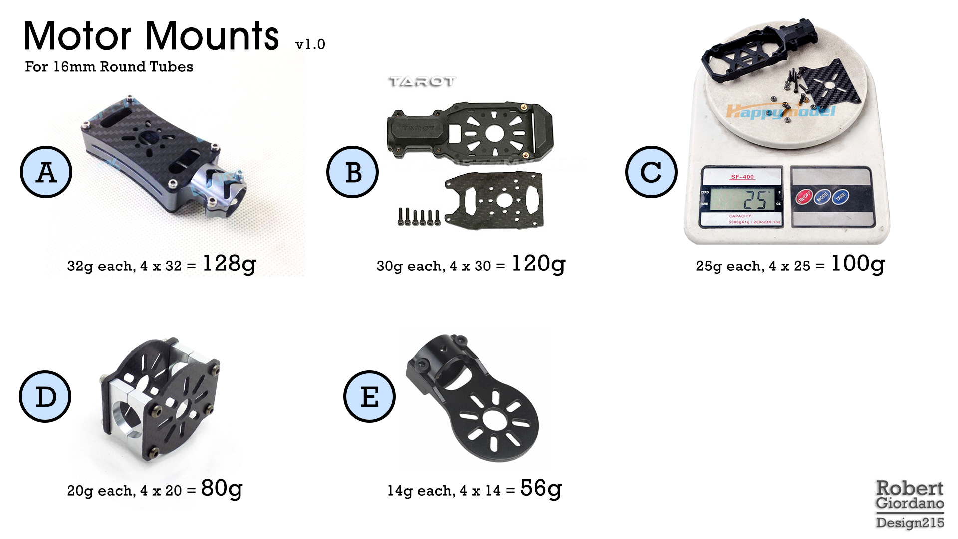
This is what I found on the internet for 16mm round tubing. I selected 16mm because it seems to be the most popular. One of the problems I face is, I don’t see many choices if I want to use 18mm or 20mm tubing. Most of the mounts I saw were variations on one of these five. They’re sorted by weight.

OMG, Those mounts are HEAVY!

I designed and built a 680mm frame that only weighs 140g and now I need to add another 100g just for motor mounts? No thanks.

Mount D

I like this style mount because you can use it for an X8 and if you’re only building a quad, you can leave off one of the motor plates. One plate and 4 screws is usually 3-4 grams so 16x4 = 64g isn’t so bad. But it’s not light enough for me.

Mount E

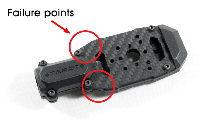
Even though this mount is lighter, I don’t like it. You can’t use it for an X8 and in a crash, it will be weaker than Mount D. Mounts B, C, and E all have a weak point where the tube connector meets the motor plate. Even the Tarot mount has a similar weak point. Look at how little material there is between the tube connector and the motor plate. A heavy motor attached to that plate will act as a lever and guess where its gonna break?

EDIT 2018/04/26: This paragraph is about Mount E and I should have used the picture of Mount E instead of the following picture of the Tarot mount because; a) I haven’t used the Tarot mount myself, and b) According to the community, the Tarot mount is pretty strong. That being said, everyone agrees the Tarot mount is heavy and I do have lighter solutions that are just as strong if not stronger.

failure-points

3D Printed Mounts

My previous ship used 3D printed motor mounts. They were designed and printed by a friend in another group. He made several sets of them and they are quite excellent:

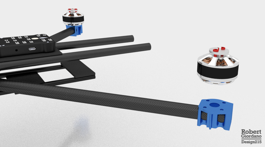
Each mount is glued to the tube with epoxy. Because they are glued together over the surface of the tube, they strengthen each other as one solid piece. Each mount AND the epoxy weighs 8g, for a total of 32g!

So, what’s the downside?

  • They were designed for a very specific, 15.26mm OD tubing. Yes, I might be able to modify the 3D file and have them printed for 16mm tubing, but then I wouldn’t have clearance for the bolts that go into the motor.
  • They won’t work for motors with a different bolt pattern.
  • They won’t work for an X8.

So, I want to make something different. But these 3D printed mounts have certainly set the bar on weight and strength!

Recent Experiments

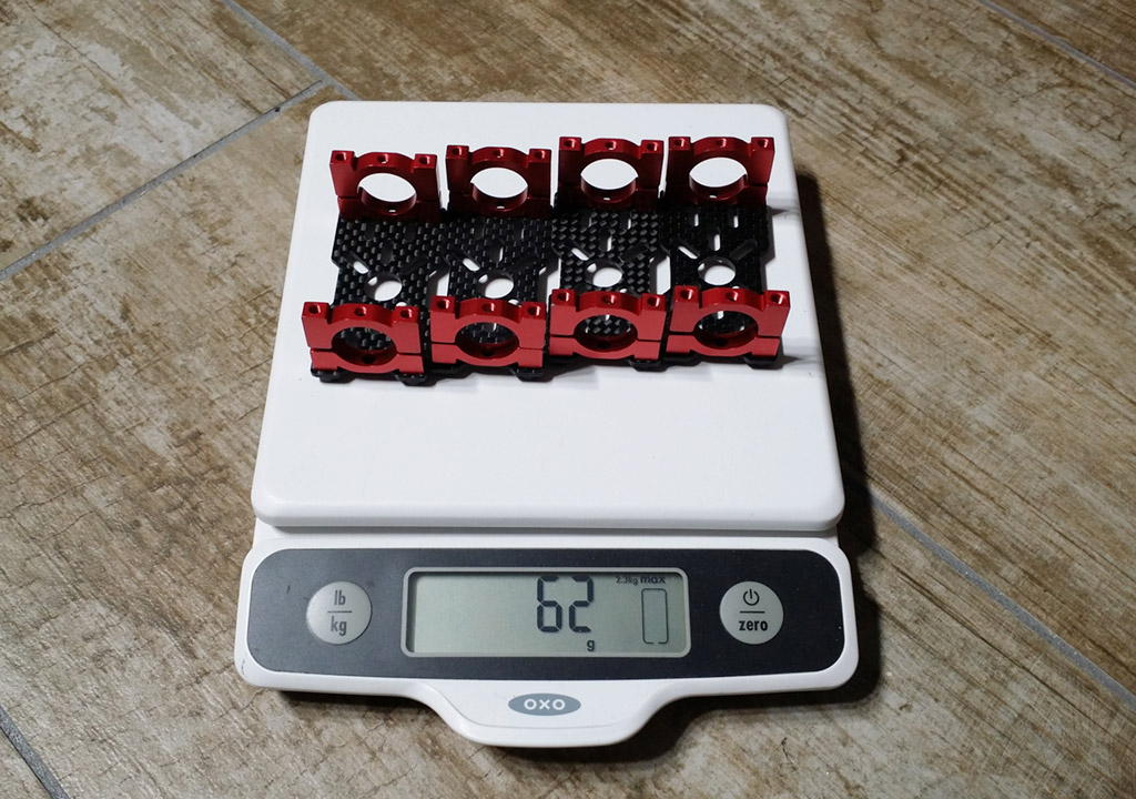
I’ve been playing with the motor mounts that came with my H4 Alien 680mm frame. They are very similar to mount D above. They can be used for a quad or an X8. I like the separate carbon fiber motor plates because they allow for a variety of motor sizes and bolt patterns, and they can be changed if they break.

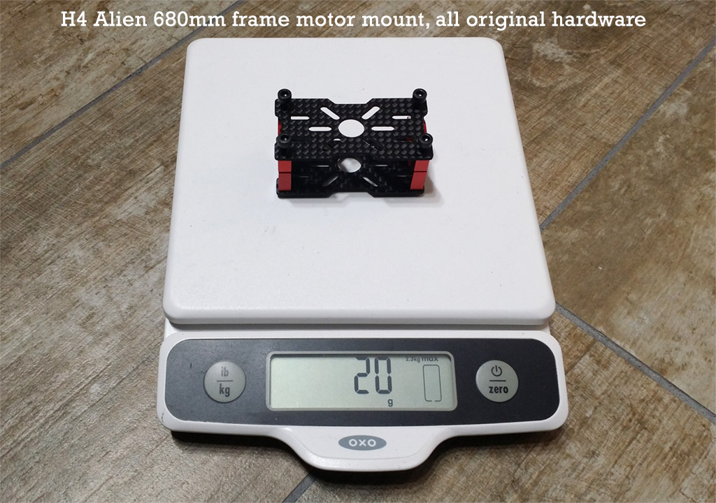
At 20g each, that’s 80g added to my frame instead of 32g for the 3D printed mounts. Let’s see what we can do with these Alien680 mounts…

Here’s all four mounts with one motor plate removed and the four screws for each plate. Now each mount weighs 15.5g. But I’m not done…

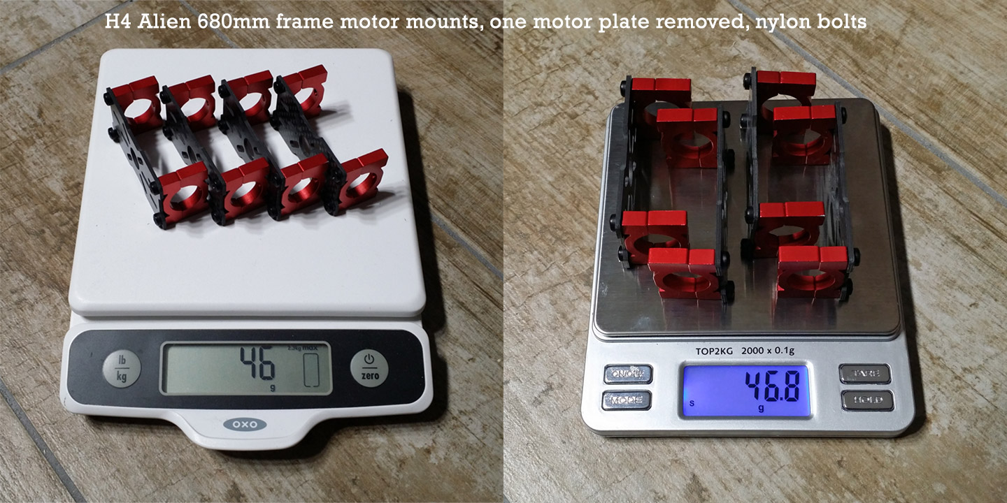
Now each mount weighs 11.7g! All I did here was switch to nylon bolts. I’ve been using nylon bolts for years and I’ve never had a problem. But I know what you’re thinking-- I won’t be able to tighten the nylon bolts enough to clamp the mount to the tube. You’re right! And, I’m not going to use the bolts to clamp the mounts to the tube. I’ll use a little epoxy between the red halves and the tube. I will never have to worry about my motor mounts rotating out of square. The nylon bolts will simply hold the motor plates. I can take the motor plates on and off without having to level the mounts each time.

Can I go further? Hmmm…

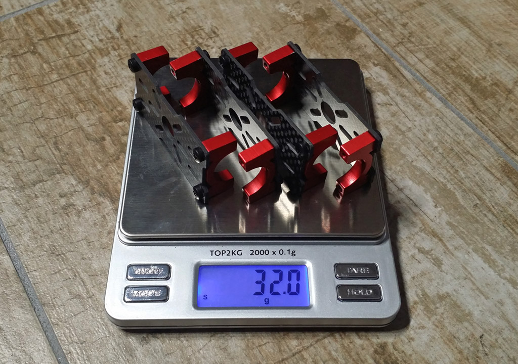
Here I am at 32g, the same as my 3D printed mounts! But wait, I don’t like it. Now I only have half the surface area to epoxy to the tubing and I don’t have the safety of the nylon bolts. Even though the bolts aren’t clamping the mount to the tube, they still go through both halves, making a solid ring around the tube. The bolts pass through one half with no threads, into the other half that’s threaded all the way through. So far, the 46g solution looks the best.

But what if…

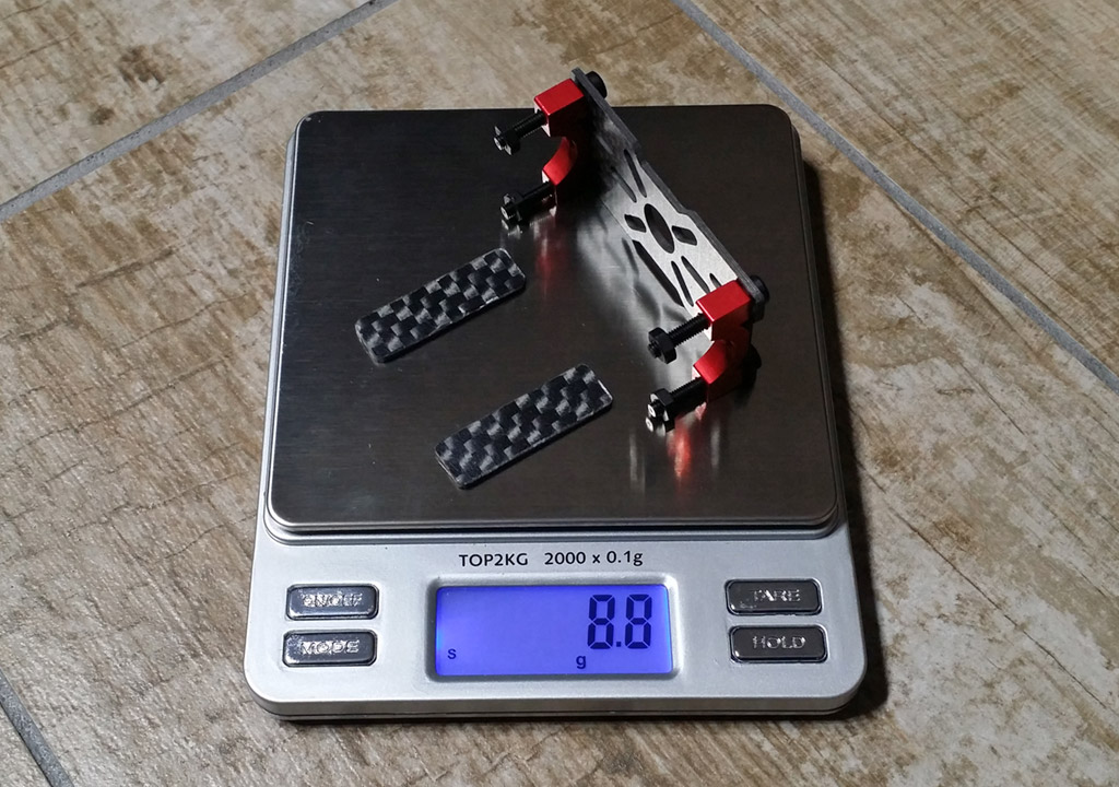
What if I used the lighter halves of the red tube clamp (the ones with no threads) and cut some pieces of carbon fiber plate (10mm x 32mm x 2mm) for the bottom side of the tube? The answer is 8.8g each, or 35.2g total! And, now I have some safety once again because the mounts are held on by epoxy and by the nylon bolts running through my carbon fiber plates on the other side of the tube. If I want to change it to X8, I can just use the other halves of the tube clamps and I’ll be back to the 46g configuration.

If you’re worried about the nylon nuts coming loose, use a little CA glue. If you need to remove them, you can cut the nylon bolts like you would a zip tie. Personally, I don’t worry about nylon bolts coming loose. They are naturally self-locking. I’ll probably do a separate post just on nylon bolts.

What about square tubing?

Well, I’ve been thinking more and more about square tubing. As it turns out, the previous solution works even better for square tubing…

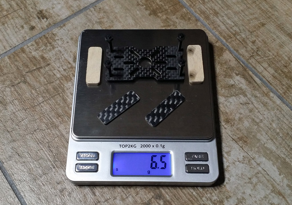
There you go! 6.5g each and only 26g total! All I did here was replace the aluminum tube brackets with 10mm x 32mm pieces of 1/8" birch plywood. Sorry I didn’t drill holes for the picture but you would run the bolts through the wood, which just acts as a spacer for the motor shaft and its bolts. The mount bolts continue though the carbon fiber plates on the underside of the square tubing. The wood spacers are easily epoxied to the tube because both surfaces are flat. If you’re only building a quad, I would epoxy the carbon fiber plates as well.

Here’s where I need your help…

Looking at all of this, I think a great solution would be 3D printed “rings” that are similar in size as the red aluminum tube clamps. But instead of each side being two halves, each side would be single “ring” that slides over the tube and is epoxied in place. The rings don’t need threads, just a hole on each side. Bolts would run through the rings, then through the motor mount plate, and secured with nuts. The carbon fiber plates on the bottom are no longer needed.

Rings could be printed for different sizes of tubing, including square. If you’re building an X8, you would just add a second motor plate.

If any of you would like to help me make some of these, please let me know. I don’t have a 3D printer and I don’t have any of the software people use to print things. I can create nice looking 3D models in Blender if that helps. I think this system could work really well. It would be stronger and SO much lighter than anything else I’ve seen!

Where do I get nylon bolts?

Local hardware stores have them but you’ll pay a lot. The best place I’ve found is McMaster-Carr. Here’s an example: Nylon M3 x 0.5mm thread, 20mm long, black, $7.87 for a pack of 100.

There is my version of carbon fiber motor plates with 3D printed ABS mounts (motors sits on rays with inclination): http://a-photo.in.ua/albums/misc/3d/motormount-3.png

If you want, i can model your version of mounts and provide file for 3D printing.

1 Like

Very nice, I hope you don’t mind if I have many questions…

How much does your complete mount weigh (including bolts)?
Do you glue the ABS parts to the frame, or does it clamp?
How many degrees is the motor tilted?

I been researching about tilting the motors slightly to improve stability but I haven’t found any actual science yet, just many people guessing, lol.

Don’t remember weight, and hard to tell now - it’s mounted on quad. However, i can estimate weight in CAD if needed.
Mounted on thin doubleside adhesive tape, mostly to prevent rotation when tightening screws. Possibly gluing on epoxy is better solution (except possibility to unmount them back).
Tilt is 5 degrees.

1 Like

Certainly not where you’ve marked it, I’m guessing you’ve never actually held one of these. The only way it would break is if you crashed at speed from a height onto concrete - they’re very, very strong. They have a design flaw but it’s not there. They are very heavy and really overkill for most motors but they have the advantage that they fit over the end of the tube and extend the arm length, and they’re also good for mounting ESCs underneath the motor - ie. they’re a good integration unit. Tarot also do 16mm vibration dampening mounts made from aluminium which are nice if you have clunky motors/props.

I don’t know many people who would trust safety and potentially expensive payloads to nylon bolts, and gluing things in place is tricky and permanent. ‘Building a better quad frame’ shouldn’t mean sacrificing practicality and pragmatism for numbers on a scale. Lighter != Better.

The alien mounts look to be copies of the original tarot 650 mounts, which worked well, and I like the ideas you’ve come up with. @Tobinejumi’s mounts look really nice. Double sided tape (or even single sided) is an excellent way to stop the mounts rotating on the tubes and much easier to undo than epoxy.

2 Likes

The double sided tape is a good idea! I will do an experiment to see how strong it is with my nylon bolts, thanks! The thing about using epoxy is it makes the tubing stronger too because everything becomes one piece. You can still remove the carbon fiber motor plates.

If I model my mount idea in Blender, what file formats can you import?

I’m using (and recommend to others) Autodesk Fusion 360, it’s free for hobbyist using and powerful. It’s can import STEP, IGS and variety of mesh formats, but meshes needs some more efforts to editing.
You can send me just hand drawn sketches with dimensions, thats enough.

1 Like

Thanks for your feedback. All good points.

That is correct. I have seen some cheaper copies, like mount “C” and that’s where they break. I just don’t want to add 120g in motor mounts to a frame that only weighs 140g.

And that’s fine. We can make lighter motor mounts and still use metal bolts. With my 8.8g configuration, changing the bolts back to the metal ones, makes it 12.4g each.

Yeah I totally agree with you there! I love my tarot 650sport frame but it’s sitting in the cupboard because it’s too heavy. I only use it when I’m going to do an important job that I need maximum reliability for, or retracts.

1 Like

I would agree with fnoop that those Tarot plastic motor mounts are bullet proof. They are heavy tho so I don’t use them.

The problem with the square tube is that I think you will find that none of the typical plate mounts you showed with your wood backing plate are actually wide enough to straddle a 20mm tube. I also would never use nylon bolts they just can’t handle the load. Also I would be concerned about slippage if trying to straddle the tube.

I use the Tarot anti-vibration mounts which are surprisingly light, except the X8 anti-vibration mount which are surprisingly heavy, and I just bolt them to the tube. But the square tube will deflect when compressed in the middle making that attachment a problem.

and Sir, epoxy- ing or bolting the motor mount, before checking the motor balance: ? your comments.

OMG how did I completely missed this blog until now ? Excellent. Keep up dispensing the right knowledge.

2 Likes

Actually, quite a few of us that are in the know do use non-steel bolts in most all applications. It’s a matter of understanding the properties of Nylon. We use two types of materials to mount motors and props and structural components: Nylon or Aluminum. Never use steel unless you need ferrous properties. It weighs too much … and the red and blue Aluminum parts are rather pretty.

When to use Aluminum.

  • high motor torque exceeds nylon shear/vibration capability given available bolt holes
  • high motor temperatures would degrade the shear capability of nylon

When to use Nylon

  • when not using Aluminum (typical four-hole moderate size motors)
  • when shearing away the motors (heavy part of ship) can save the ship structure in a crash
  • when on a ship where duration is important
  • for most all spacers
  • for most all washers
  • for most all nuts
  • for most all connections when joining structural elements
  • on lock nuts

With nylon, check tightness prior to flight. You can also use nylon like a locking nut by using Imperial sizes on metric. But use care.

Off the top of my head, I can think of only one reason to use steel … in the motor housing to contain the magnetic fields. But I’m sure there are others as well (but many of those can be fulfilled by Ti).

2 Likes

Great information! Perfect timing since I know a guy that is just getting into this!

1 Like

Cost, availability and overall ease. For some the extra weight is not as much of an issue as being able to easily source the parts and/or worry about integrity of build after hard “landings”. Again, we get back to defining the use case and context. If you are worried about weight to the point of using Al or Ti then you are likely spending some cash, and building a wood frame may not be a match to Al and Ti fasteners.

Also setting and checking torque on a nylon fastener if you are into such things. Most DIY builders probably not using a torque wrench and/or production quality assurance practices. Probably overkill anyway. Unless you are concerned about your nylon fastener being over torqued and stretched too far. Or if it’s been in a crash and taken beyond yield but not ultimate, so now it’s deformed and you do not know it. I guess you could institute an NDI program.