Just wonder why does FPV or DJI minis have the GPS antenna so close to the FC and power wires but isn’t affected by it but GNSS modules from pixhawk, orange cube etc have problems operating near the FC?
Is it using a ceramic antenna?
Just wonder why does FPV or DJI minis have the GPS antenna so close to the FC and power wires but isn’t affected by it but GNSS modules from pixhawk, orange cube etc have problems operating near the FC?
Is it using a ceramic antenna?
The gps is fine with magnetic fields, it’s the magnetic compass that’s integrated into it that has problems with power cables. DJI phantoms used to have the compass mounted down in the landing gear as far from wires as possible.
The problem is not only the interference on the compass, indeed there are more problems on the gps due to EMI. I have a 4" copter that works perfectly and has never had problems with the compass, instead I’m going crazy with the GPS which has fix problems because the TF luna lidar emits a lot of EMI despite having shielded it with a special EMI tape
Yes that’s a whole other issue, lidar lite is badfor it too.
Yea I tried to shield with EMI tape but still if its too near it send my compass hay wire. Now I am just got to make do with having a long protruding ugly gps antenna sticking out. Just wonder why FPV drone doesn’t have the same problems…? I know they fly in acro there is no need for gps but alot are outfitted with one for emergency.
so it works, but if I turn on the lidar which is on the front I have many GPS glitches and the flight is not safe. without LiDAR flies well in loiter
FPV drones fly in acro mode and do not need nor use magnetometer nor GPS receiver.
You are comparing apples with potatoes. Those are all very different.
In case of DJI their products are fully integrated and tested by experienced engineers. With ArduCopter, inexperienced users place unschielded, untested, electronics near each other and wonder themselves why they interfere with each other.
Someone that knows about EMI and EMC simply will not compare apples with potatoes. He just knows that to get DJI like EMC he needs to spend a couple of dozen hours in a EMC chamber with measument equipment adding filter after filter. After spending the effort, you get the results.
There is no way around that.
Or … You just keep the magnetometer and GPS receiver away from the other electronics like everybody else ![]()
You’re right, an EMC chamber would be needed! Without that you have to proceed by trial and error!
Of course we all know it takes alot of trial and errors to get the best outcome for us DIY drones. EMC is not cheap to do. But I’m sure there are basic principle advice people who knows well could give. After all we are here to try to make our drones better or at least learning to.
I actually tried ardusimple. The antenna seems not very affected by the interference. I assume it has to do with the type of antenna as well. In additioa, ardusimple doesn’t have compass which is another added point.
I am suspecting internal antenna design might do just as well but I need to do more test. As the ceramic bottom helps protects it from interference.
I wonder if your antenna is place on top might work better than the side. The ceramic bottom suppose to absorb the interference. Just my guess.
If you do try, please let me know the results. I am quite interested.
For anyone find this useful.
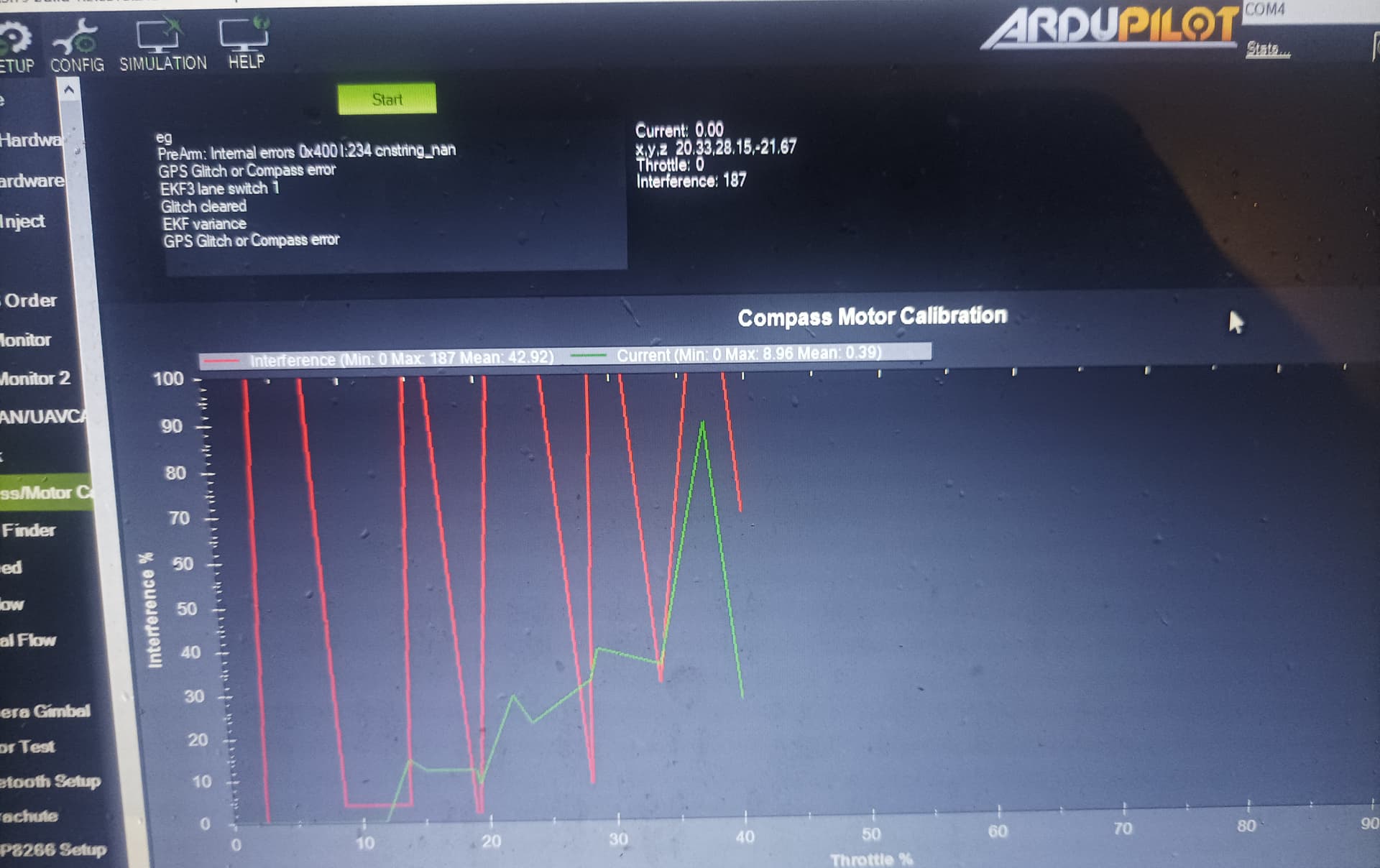
I found ardupilot can actually test for interference.
The normal solution Is to just disable the internal compass, it’s too close to power wires to be useful so trying to use it for redundancy is pointless
As @geofrancis stated this has been known since compass’s have been included on flight controllers/IMU’s. The original APM even had a GPS module on it which was soon recognized as a terrible idea. The only reason FC’s have them now is if they use a 9-axis IMU.
Yes, internal compass perhaps works on bigger drone where there are spaces between fc and the wires…
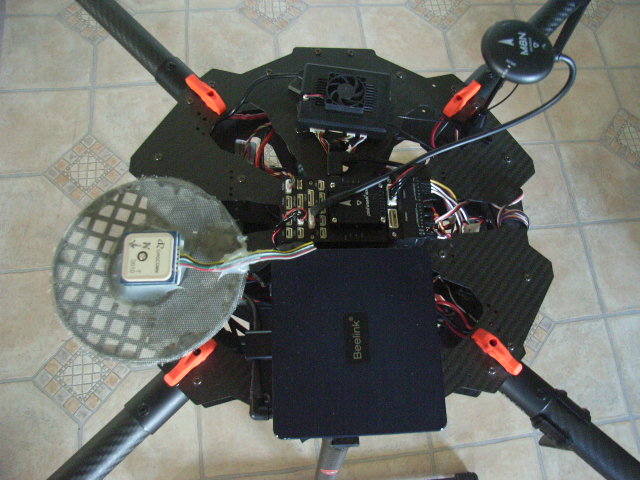
This may help or at least provide some ideas in regards to GPS reception:
My GPS Setup - Not pretty but works well.
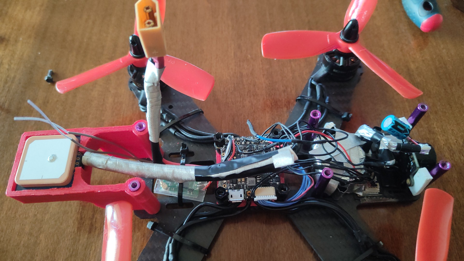
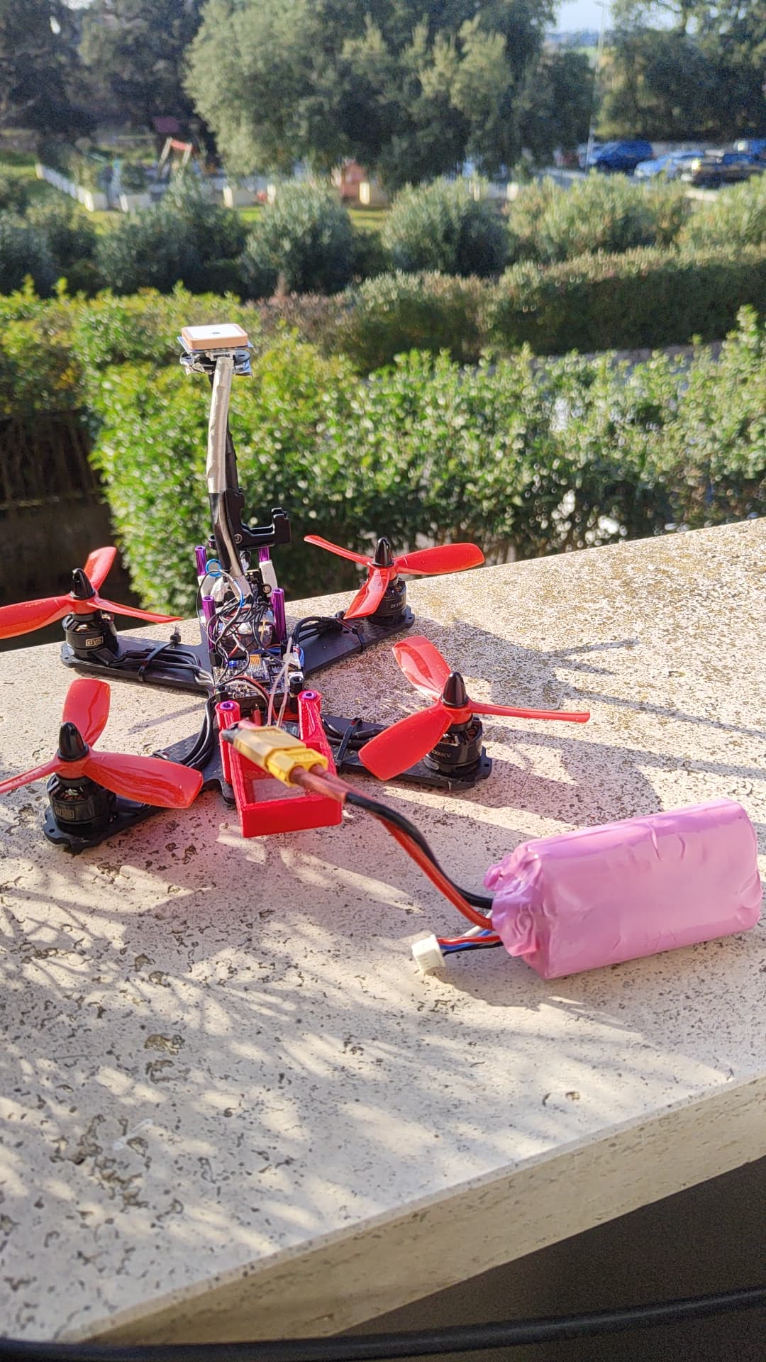
i did a lot of tests. also to augment the ground plane with a fine copper mesh. i also shielded the 3d printed holder with EMI tape. nothing works right, just the stylus that raises the GPS. however I’m working with a small 4" copter with LiDAR and sonar. very difficult environment! on a 10" it would be easier. my aim would be to eliminate the delicate GPS stylus
I can see your challenges on such a small platform.
The grounding plate / mesh needs to be overhanging the sides of the GPS receiver or be raised at the sides to be fully effective.
But have to admit I haven’t done any tests as to how much overhang is required.
Just had an idea:
There used to be this special, somewhat conductive 3D printing filament available. - Used to be applied to build cases for electronic equipment /boards.
This may fix the issue with creating a RF shielded platform whilst allowing you to create a small platform compared to other solutions.
One example:
Another thing that can help with your problem:
Twist all wires if possible. Especially the battery and ESC wires. This will reduce RF interference.
I used one of these
https://www.3m.com/3M/en_US/p/d/b00050680/
The wire mesh usually I used in any ventilation opening.
Carbon fibers are electrical conductive, technically the emi shield ideally should be grounded with the structure. A small piece can only take insufficient charge. These are just theory, I guess a lot of trial and error is required.
My gps antenna is about 5cm to 8cm from my fc, thats the lowest it can go. I can see your drone is much smaller than mine which makes the gps look exceptionally long.
I have little space because the copter is small, but the gps could still work well even with the printed support. The problem is the EMI lidar for GPS and partly the sonar for the compass.
I shielded the ildar with this conductive tape and with other EMI tape, on the bare part of the lidar PCB I also put a copper mesh connected to the GND of the FC. I shortened and shielded the signal cables as much as possible.
Here you see something:
The conductive PLA might create some problems for the compass I guess… hard to tell without experimenting