New LiDAR sensor Benewake TF02-Pro TFmini-S TF-Luna for drones UAV

You are right but it is hard to find. I have a very dense copper network, in the meantime I’ll try that

Easy enough to find (depending on where you are I suppose) but very expensive for a trial.

@ibrahimqazi @dkemxr @amilcarlucas

Hello everybody. i tried a double layer of copper mesh and lengthened the gps stand holder. Does not work. I interposed a further copper mesh layer but nothing. I laid the TF luna FC connection cables under the copter frame and finally the situation seems to have improved. I think I’ll have to try a very short shielded cable.


I have to replace these cables with shielded and short cables


Yes its better to keep the wires shorter as shorter as possible. Plus, twist the IIC wires. You could also try wrapping GPS in anti EMI sheet and see which one gives you greater number of satellites.
image

1 Like

As mentioned by @ibrahimqazi,
Shorten the wires and twist them. The Luna TF wires too.

General advice: Avoid a rats nest of wires. They work very well as antennae for RF noise.

One more: Check the supply voltage of the Luna. These devices are a pulsating load on the supply line. Not every DC-DC converter (voltage regulator) can handle this.

2 Likes

@ibrahimqazi thanks!

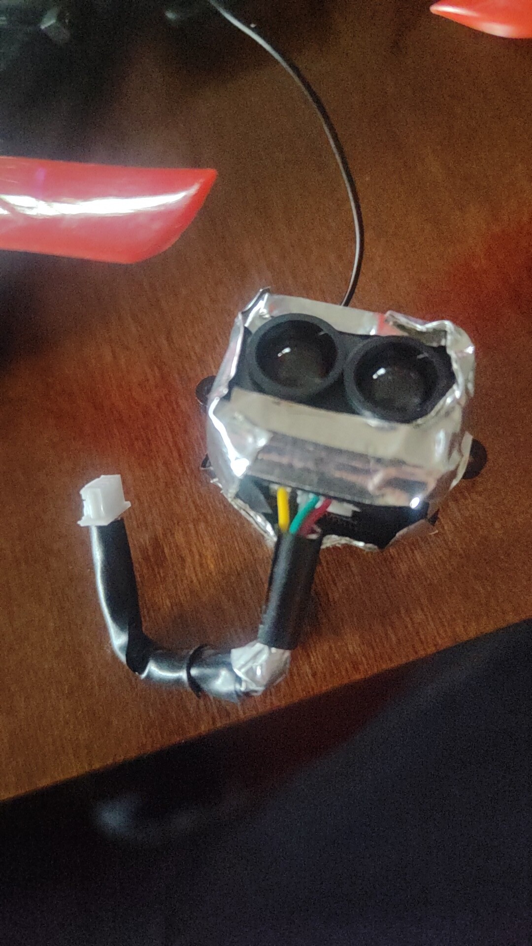
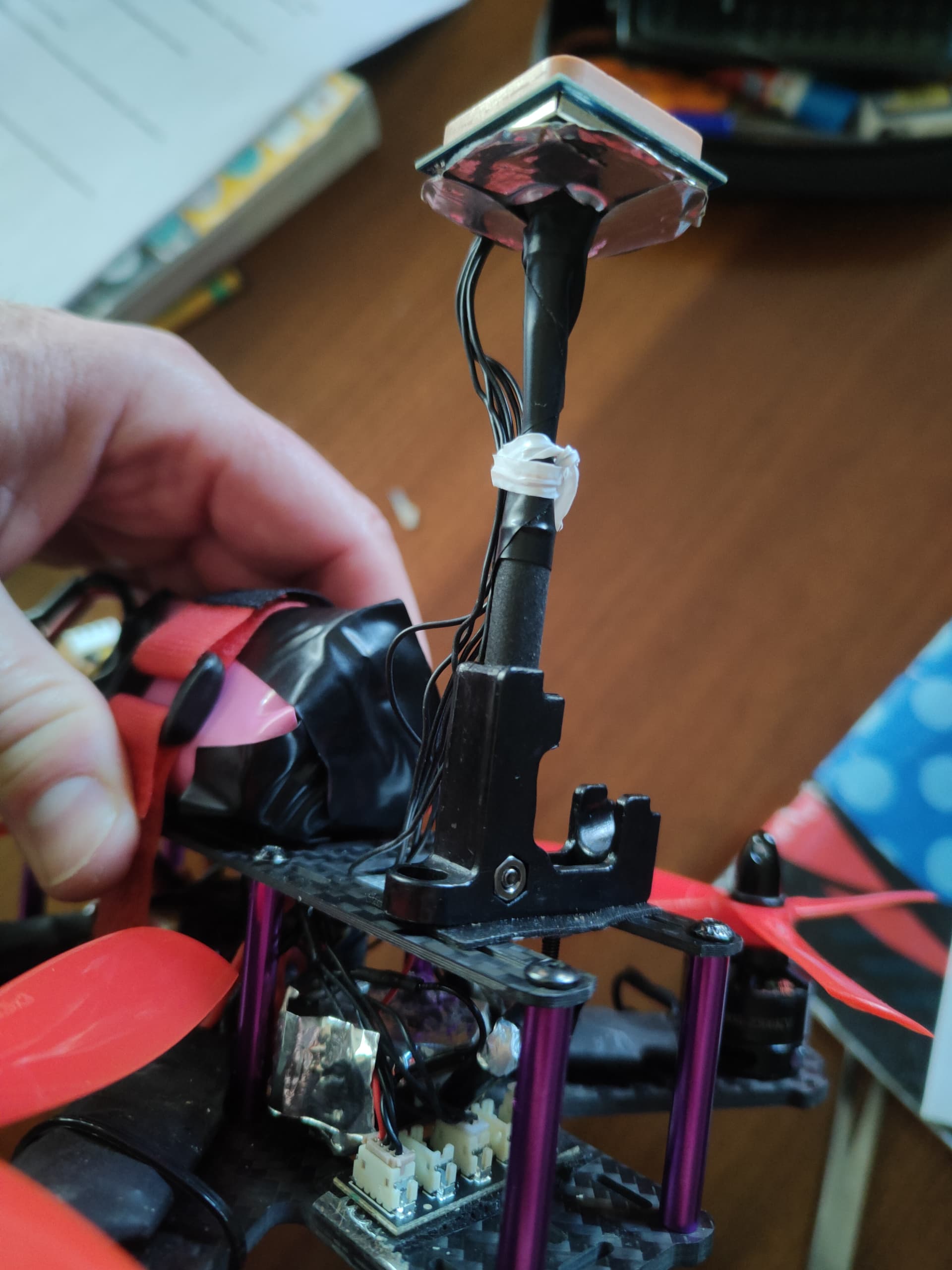
I shielded and shortened the cable. I enclosed all the TF luna in aluminum that I connected to gnd (tested with a multimeter). I moved the GPS even further away. unfortunately the GPS fix is ​​very slow and I still have GPS glitches. do you have any proposal to block EMI, possibly from AliExpress? i don’t understand why make a lidar so small, that it should go on small copters (mine is 4") and not design them already adequately shielded.

Without this problem, works well

A few years ago I made a “poor’s man ground plane” for the GPS using a single sided PC Board, it really helped

1 Like

@ibrahimqazi @ppoirier

i will also try the pcb as a screen. Thanks.

today, with all the shielding, the GPS caught 14 sats out of 20 sats in view (after 5 minutes in flight). the TF luna still works.

1 Like

TF-Luna is the cheapest LiDAR in Benewake product list. It has no shielding.
You could also consider buying TFmini-S, the PCB has been modified which does not need that intensive shielding. A little expensive than Luna but less headache of EMI.
NOTE: Remember to buy hardware version 1.8.1 written on back side. Some resellers still have PCB 1.8 version which will cause problem similar to Luna.
image

2 Likes

Hi guys!
Is it possible to use lidar in Loiter/Poshold to reduce speed down at low altitude to prevent copter damage in manual landing?
In autoland (RTL/ Land) lidar works well
But in Loiter I can use it as avoidance only.
Thks

Practically speaking, it’s possible because there are already applications in which LiDAR is used for this purpose but I think this feature is not available off the shelf in Ardupilot. You will need to develop it.

1 Like

try to add ferrite bead over all wires coming to Luna (maybe another at GPS) closest possible to the module. Maybe your EMC travel over wires.

This is true. i2C- TFMINI+ lidar doesn’t work in current ardupilot firmware (my copter is v4.4) So many hours spent to figure out why doesn’t work even though says in the docs by setting param RNGFND1_TYPE=25 (for i2c-benewake tfmini+) and RNGFND1_ADDR =16 (0X10 default i2c addr of tfmp). Looks like its really I2C driver issue within the ardupilot firmware. The UART mode of the tfminiplus works just fine.

For me it works with the same settings in I2C mode in plane 4.4!
Did you connect Luna pin no. 5 to ground to activate i2c mode?
Luna must have also some newer firmware, but piece I bought this summer had it already in.
I don’t speak about not confusing SDA with SCL :slight_smile: .
Just extra note, that I put a ferrite bead over all four wires from luna to the FC (close to luna) and don’t have any problem with RF interference. It’s in the plane with more space so it’s ~25 cm from GPS, but has no influence to it.

Please can you clarify in the Benewake tfmini+ docs, if you switch to I2C, you send the command

5A 05 0A MODE SU

Im confuse how is that change to “5A 05 0A 01 00”.

Hello,
MODE value can be 00 (for changing to UART) or 01 (for changing to IIC). SU is checksum which is the sum of 4 bytes, you can also put 00 in SU byte, it is acceptable. So, based on this explanation, the two commands will be:
Change to IIC: 5A 05 0A 01 00
Change to UART: 5A 05 0A 00 00

Just for my understanding: Changing mode by the command is equivalent to changing it by grounding pin 5? You can’t use this method?
In EN manual I have in hand isn’t described changing mode by pin 5, but I google translated description of pin 5 in the chinese manual and there it’s written.

Here you mentioned about TFmini-Plus, right? TFmini-Plus has no 5th pin. It has total 4 pins. 5th pin exists for TF-Luna. That’s the case for TF-Luna not TFmini-Plus.

I dont have the TF-Luna. This shoudn’t be address to me.

Now I see! Sorry for the confusion. All the time I ment TF-luna.