I keep looking at the hall sensor example code to see if i can get the encoders working on the wheels, my understanding is that using the example code from Digikey to read the hall sensors we just need to then use some more code to output an emulated quadrature encoded signal.
What are you guys looking for when you purchase them to make sure you get boards that will work with the code or is it just a guess? Are you purchasing these from ebay or off local sources?
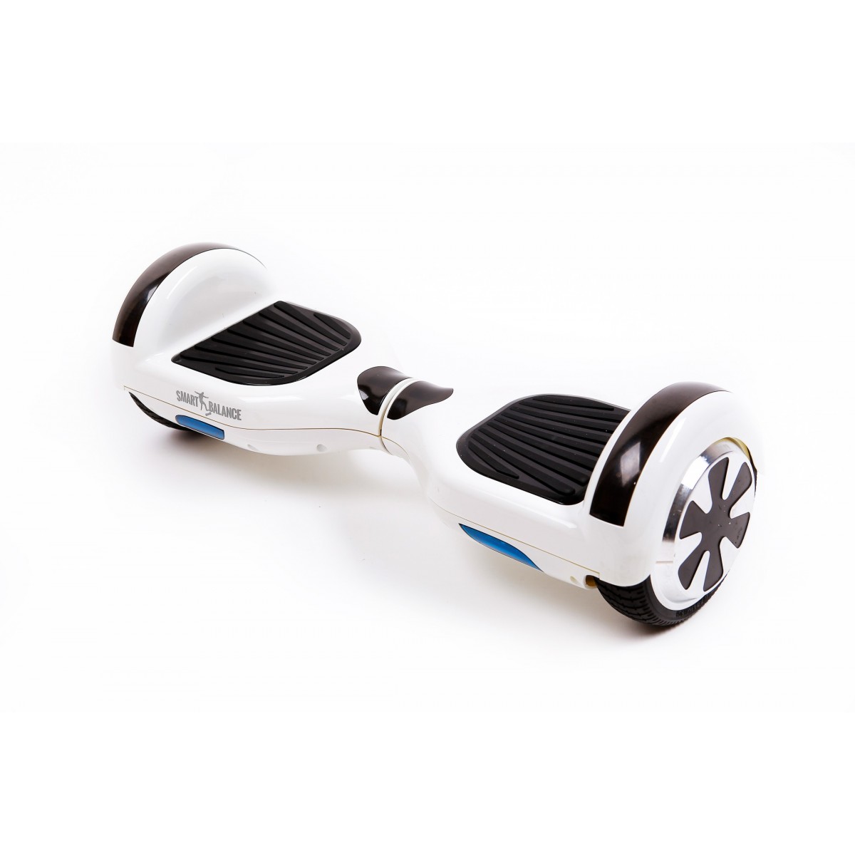
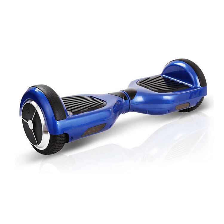
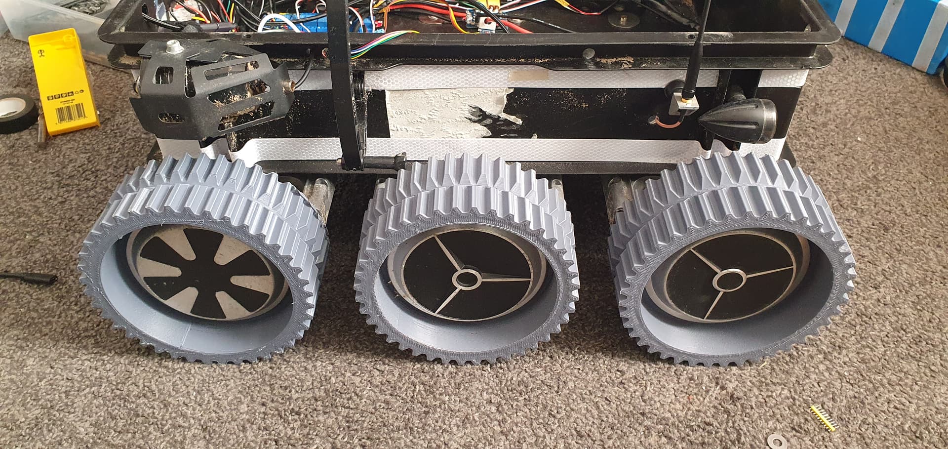
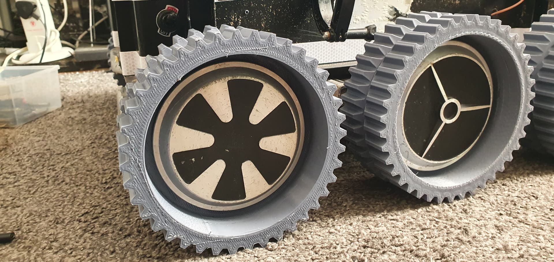
you need a classic hoverboard that looks like this, avoid anything with flashing lights. generally any with the flower or star wheels are ok. best place to get them is local, they are really heavy so shipping is generally expensive.
Avoid it if there are any screws missing, it usually means someone has already been inside it.
I can move the front and rear boards out a little of i need to but it means drilling it all again. Il probably have to anyway since i suspect its going to make a nasty noise the first time a stone gets stuck in it.
I would like to try and get a rubber belt for down the center of the wheels for when i need to move it over pavement.
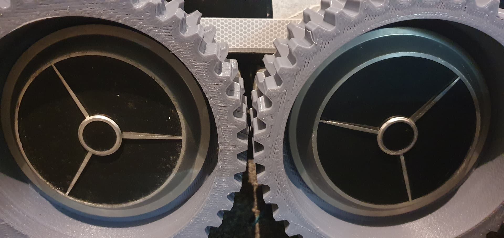
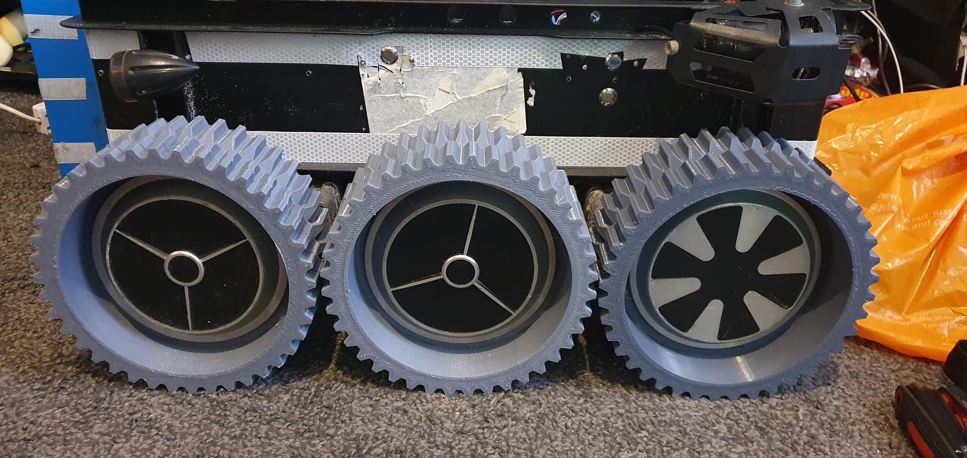
Got all the wheels fitted, turns out one of the boards is slightly off so one pair of wheels are touching so im going to have to redrill, if im doing that then I might as well space both boards out more.
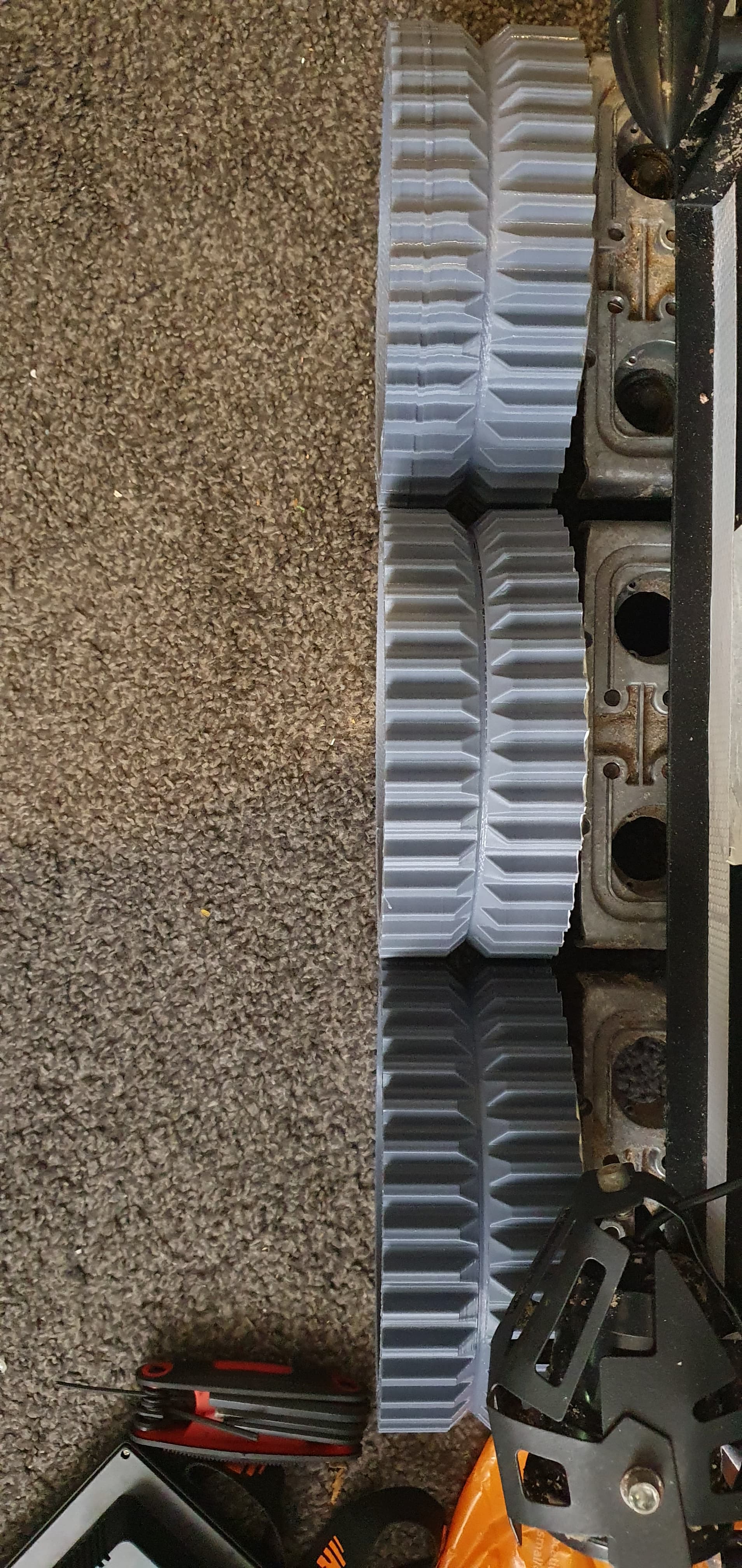
I pushed both front and rear subframes out as far as i could so there is plenfy of clearance now and as an added bonus because of the larger wheels and getting pushed out they are now pushed out futher than the chassis
I have added a bank of relays for switching off the motor controllers, I tried connecting the buttons together but it didn’t work, so each controller has to get it’s own relay since the controller button had battery voltage running through it. Pressing the toggle relay button toggles the motors off of on, I can also switch if from my transmitter. I just set it to to have a 1 Second down delay to make sure to hold it long enough that there is no way one controller can get out of sync of the others.
im working on some kind of feed back so it can tell of they are off or on. I will probably just connect one of the voltage rails of one of the controllers to the button input so it’s activated when the motor controller is powered on.
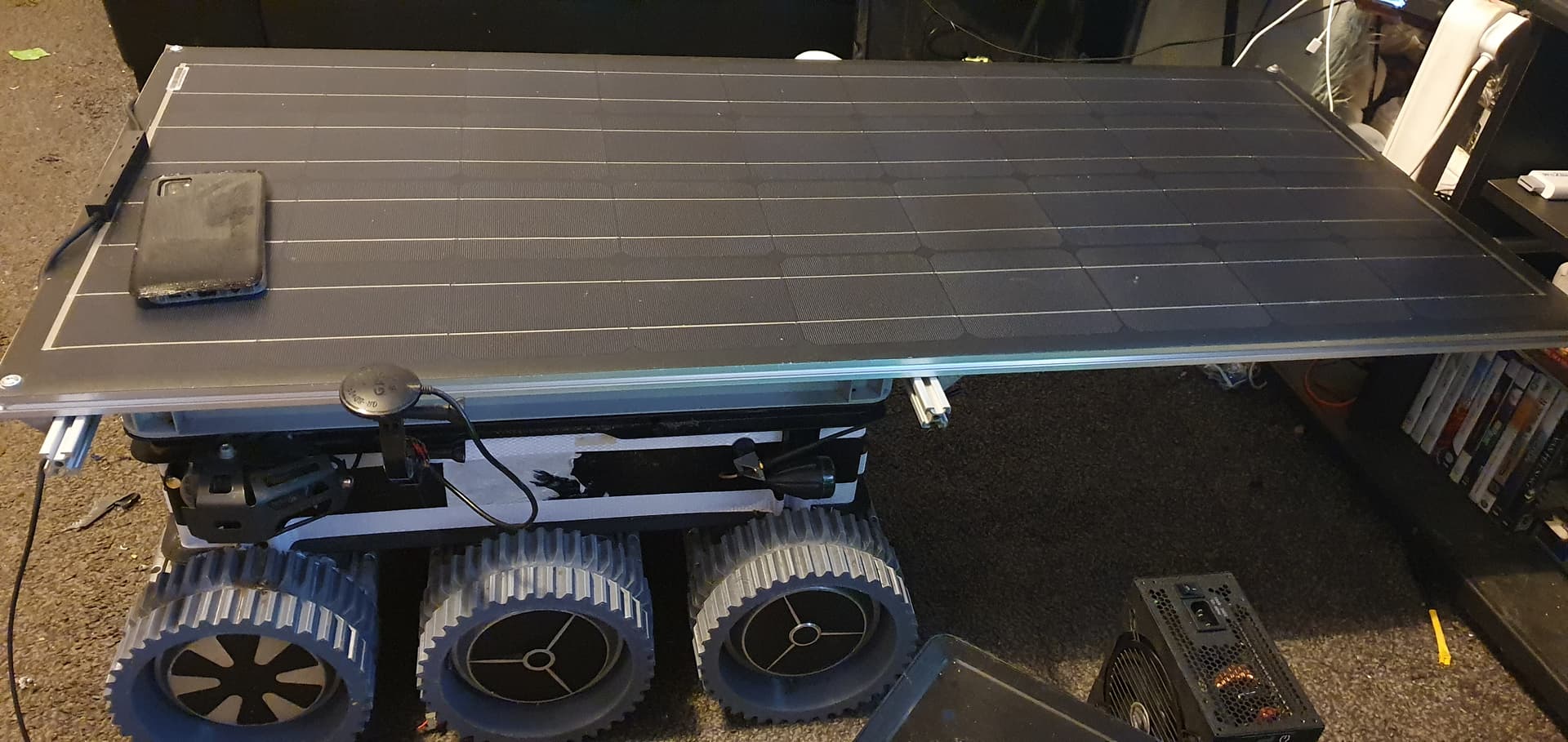
I want to solar power it and turning off the controllers halved it’s idle power consumption.
With most of the work done by @Yuri_Rage as im crap with lua, I have a working motor control script for controlling the power to the controllers. By looking for voltage on the boards 3.3v rail using the ardupilot button input and using that to determine if the motor controller is in the state required, if not the power button to the board is switched for 2 seconds using ardupilots relay output.
im only connected to the first board for feedback but in all my testing the boards have never gotten out of sync. In theory you could run one script per controller to get feedback on all of them separately.
Currently, the script powers off the motors when in hold mode and back on when in any other mode.
local RUN_INTERVAL_MS     = 200
local TOGGLE_MS           = 2000
local RELAY_NUM           = 0
local BUTTON_ACTIVE_STATE = true -- the 'pressed' state of the button
local BUTTON_NUMBER       = 1 -- the button number we want to read, as defined in AP_Button
local ROVER_MODE_HOLD     = 4
local MAV_SEVERITY_INFO   = 6

local messages = { [true] = 'ON', [false] = 'OFF' }
local desired_motor_state = false

function wait_for_state_change()
    local motor_state = button:get_button_state(BUTTON_NUMBER) == BUTTON_ACTIVE_STATE
    if motor_state ~= desired_motor_state then return wait_for_state_change, RUN_INTERVAL_MS end
    return update, RUN_INTERVAL_MS
end

function turn_off()
    relay:off(RELAY_NUM)
    return wait_for_state_change, RUN_INTERVAL_MS
end

function update()
    local mode = vehicle:get_mode()
    local motor_state = button:get_button_state(BUTTON_NUMBER) == BUTTON_ACTIVE_STATE

    if motor_state == (mode == ROVER_MODE_HOLD) then
        desired_motor_state = not motor_state
        gcs:send_text(MAV_SEVERITY_INFO, ('Toggling motor %s'):format(messages[desired_motor_state]))
        relay:on(RELAY_NUM)
        return turn_off, TOGGLE_MS
    end

    return update, RUN_INTERVAL_MS
end

gcs:send_text(MAV_SEVERITY_INFO, 'Motor toggle script active')

return update()
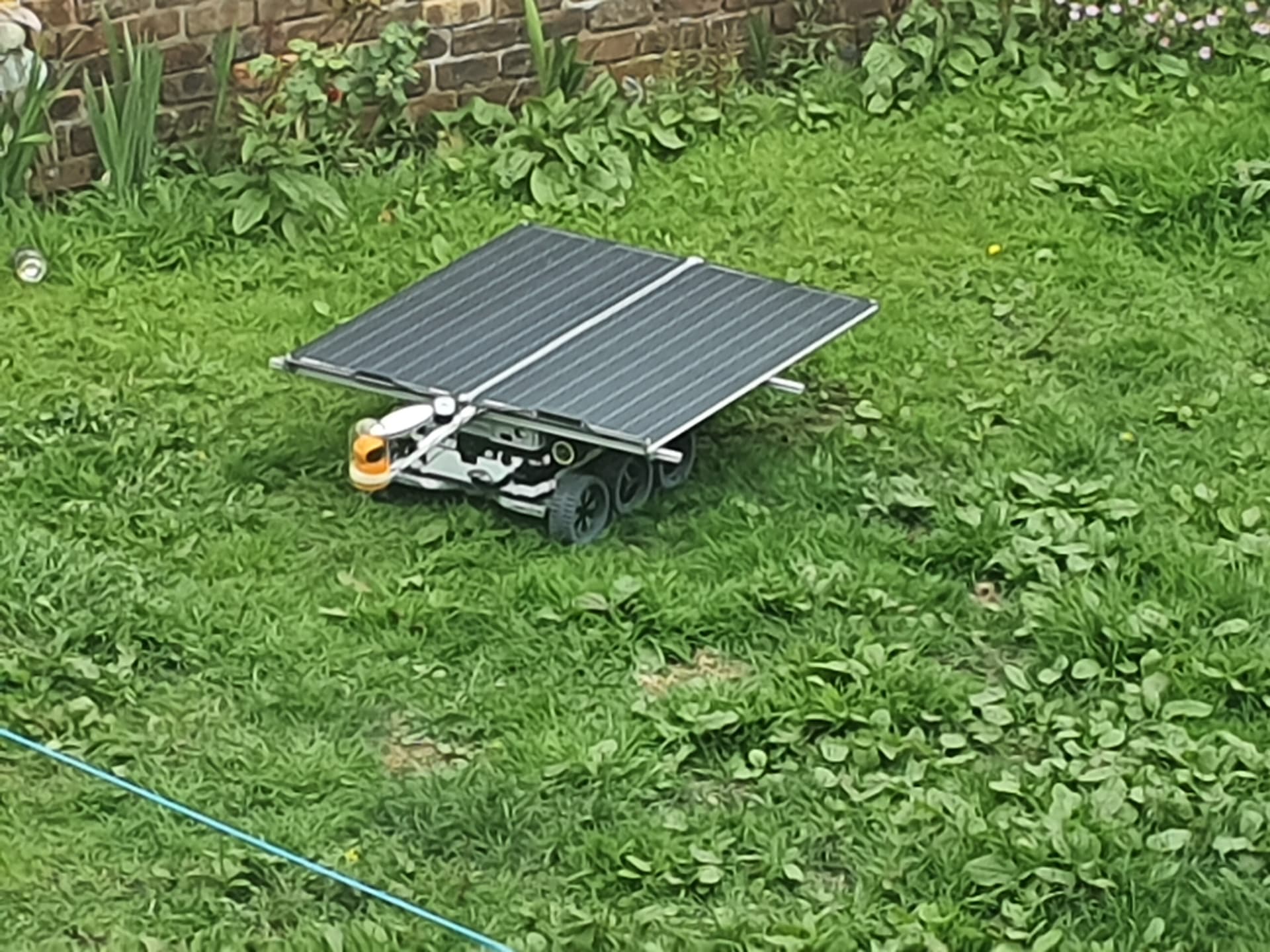
My rover just spend its first night outside. Its got 2x 100w solar panels on top of it and a mppt charge controller. The plan os to leave it in the garden for a few days to make sure the controls stay alive then its getting take to the beach to do laps if all goes well.
I have added one of the espeasy home automation controllers so i can get alerts to my phone of it detects someone messing with it. As its got an omni dorectional radar and pir.
its been out for 9 days now in the sun and rain, so far the little gps compass module has failed and the VL53l1x range finder has failed both due to rain ingress. other than those 2 failures and some video issues using Andruav, (thanks to @MHefny we narrowed it down to a problem with the video encoder in Samsung phones). all has been working well.
It’s setup so its all running over the onboard phones LTE connection, RC is sent by using mission planner joystick interface. To connect my taranis radio to mission planner i have been using one of these wireless trainer dongles. it gives channel 1-8 as analogue inputs and 9-16 as switches and supports failsafe so your not tethered to the computer. I have it programmed so i can switch between the frsky module or just change profile on opentx and connect over the backup UHF link.
Took it for its first drive, I had to drive it about 1/4 of a mile down a quiet road to the park do a lap of the park and come back. video was flawless the whole way there, It got some strange looks, A few people stopped and were taking photos and I had to pull over to the side of the road to let some cars pass. Unfortunately, the USB port I was using for charging just couldn’t supply enough power and the phone ran out just as I was leaving the park. so i had to walk to get it and drive it back LOS. but thats a minor fix.
I have replaced the compass and recalibrated everything so it should be ready for running in auto mode. Once I’m confident it can navigate im going to set it to do some laps of the park. The rover only uses around 40w when running on flat terrain according to the power sensor. so with 200w of solar onboard it should be able to run non stop as long as its daylight. The only thing i have to finish is a lua script that will check the battery voltage before restarting the mission. That way it will do a complete lap before stopping to charge rather than just stopping randomly.
I was given some information from someone but I cant find their post, They confirmed that you can just connect any 2 of the 3 hall sensor wires to ardupilot as a wheel encoder and it just works. The line is a little jaggy when you look at it on mission planner but the total count still works so it should work for navigation.
I have been doing some more testing with the motor controller modes and for ardupilot SPD_MODE is the way to go. I had been using the default VLT_MODE mode up till now and it was ok but on a tank steering vehicle it made it really hard to drive at low speeds as you would have to apply a lot of power to get it to break traction to turn, so it would be very difficult to control at low speeds as it would jerk when it broke traction.
Using SPD_MODE is very different, it behaves more like hydraulics where your controlling the speed and it doesnt change with load so when driving at very low speeds its movements are very smooth and predictable. this mode is also compatible with a function on the controller called “stand still” where it will use power to hold the motor exactly where it is . This is the main reason I changed the control mode as I was really worried about driving over a hill and loosing signal and the rover rolling down the other side of the hill uncontrolled. this way it will not move unless commanded to.
the only other change i made to get this mode working was increasing the dead zone, the 3 controllers I have the mid point doesnt line up exactly so I had to increase the dead zone a little. I would prefer to make some kind of digital adapter then I dont have to deal with tolerances
I have wrote a SBUS to IBUS adapter so the boards can be controlled totally digitally this is the best way to keep them exactly in sync.
I have flashed my 3 boards to IBUS firmware and they are now all working beautifully together, you would think they were mechanically coupled.
I have enough spare parts to build another 4wd rover,
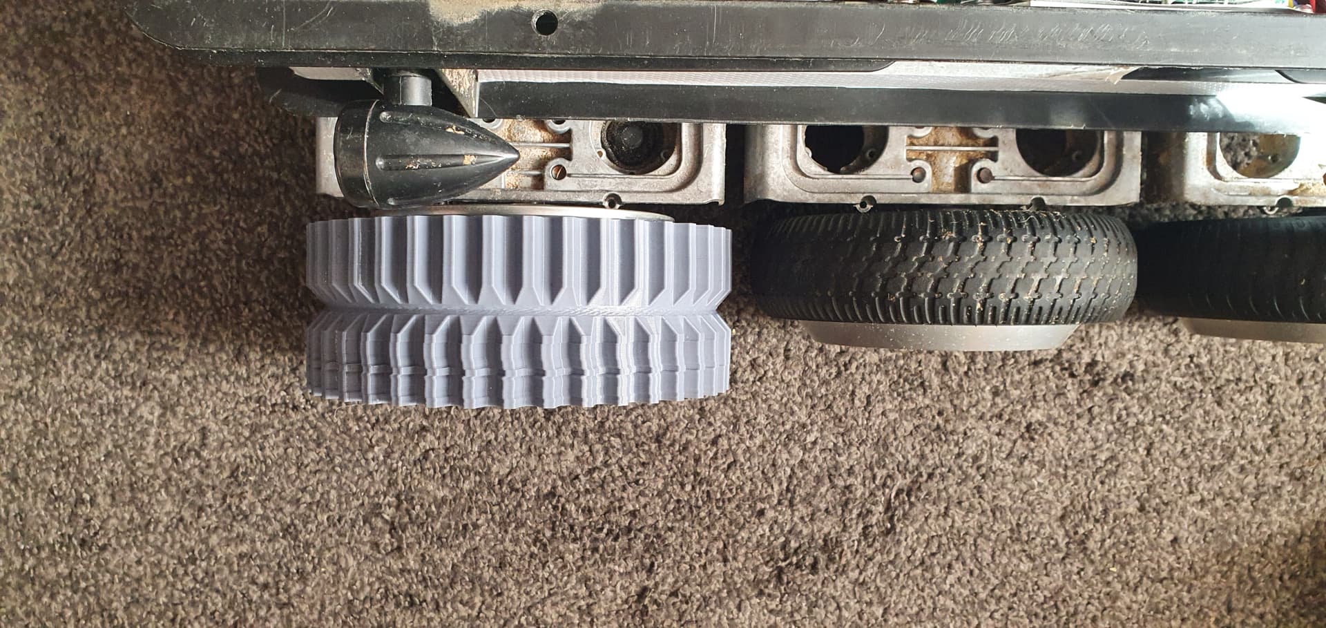
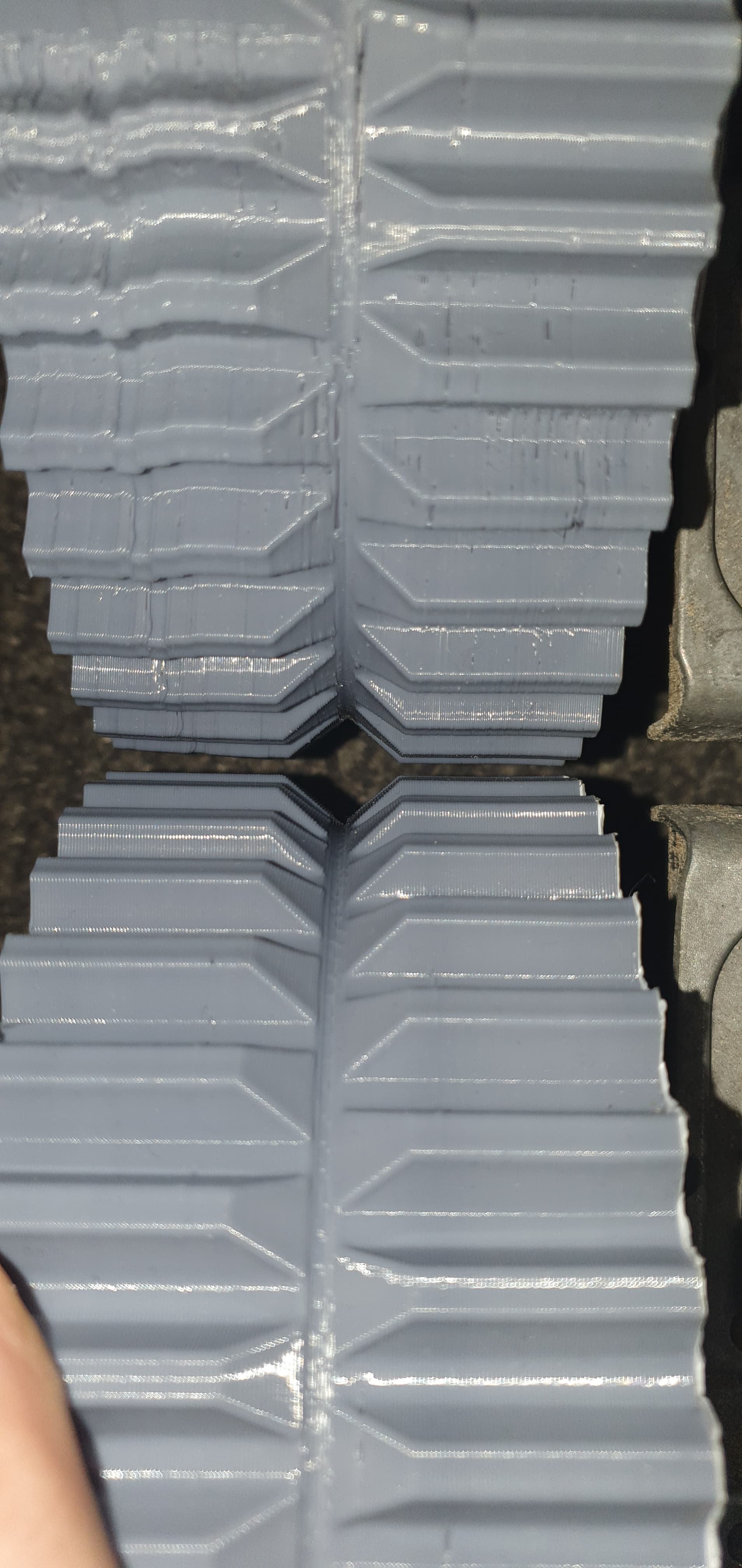
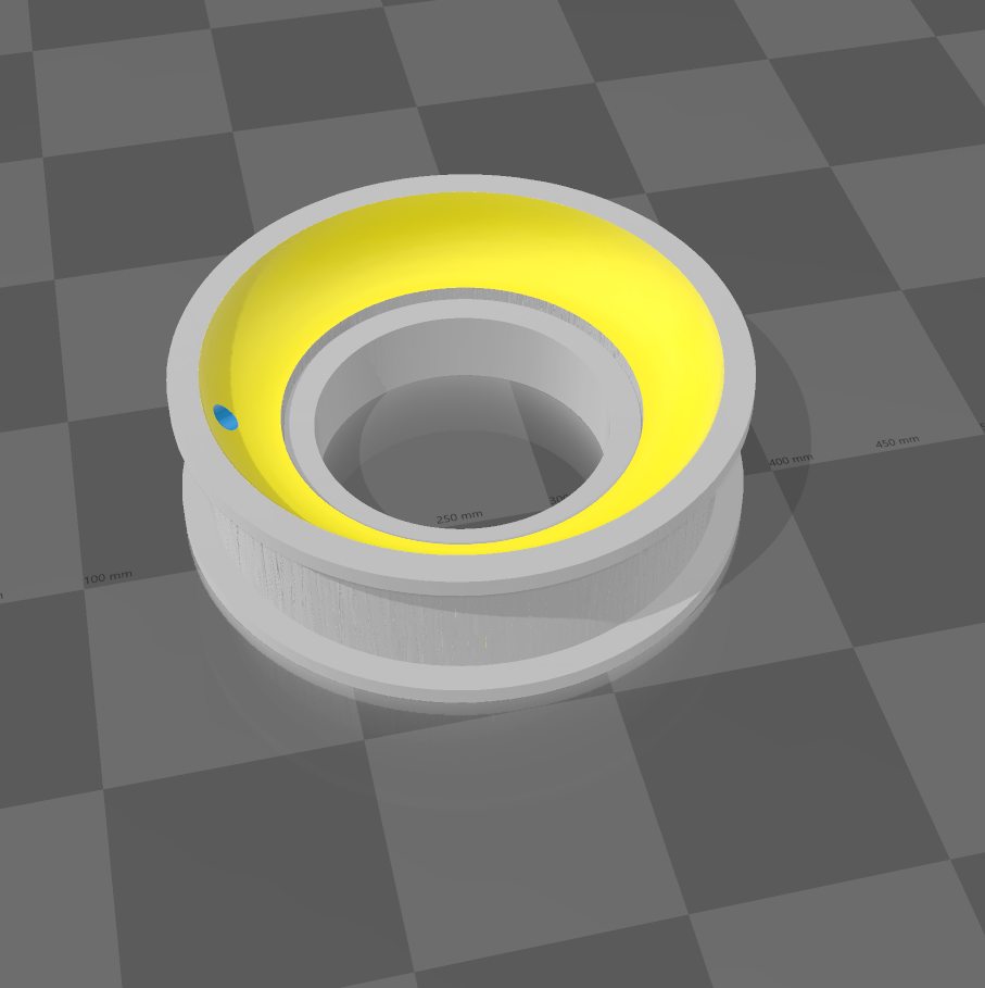
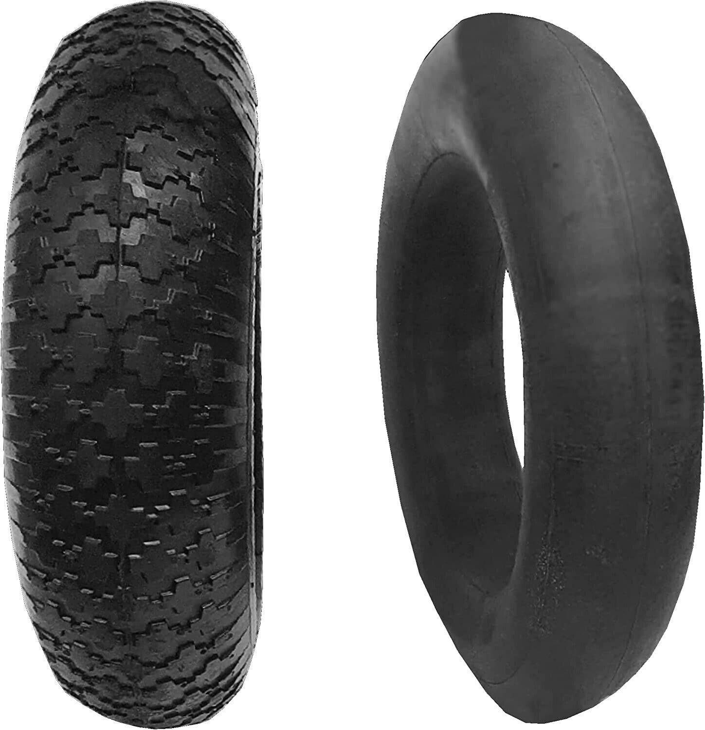
My plan is to build something better suited for urban driving so rather than the stock rubber wheels I want large pneumatic tyres that could go over large kerbs. the problem is that 5 inch tyres are very expensive as that’s the size that mobility scooters use so to get e 4.10 / 3.50 - 5 tyres I would be looking at almost £35 per corner, that’s far too expensive. but while browsing i noticed that I could get 3.50-8 inch tyres with a tube for £8.50 per corner as they are made for wheelbarrows so are much less durable but fine for my use.its a much better price so that means i just need a way of making it fit, Since I already had the files for the previous 3d printed tyres I could use that to mount it to the hoverboard motor and simply add a rim to it for the tyre to fit.
I have the first one currently printing, its about 450g of filament and will take about 2 days.
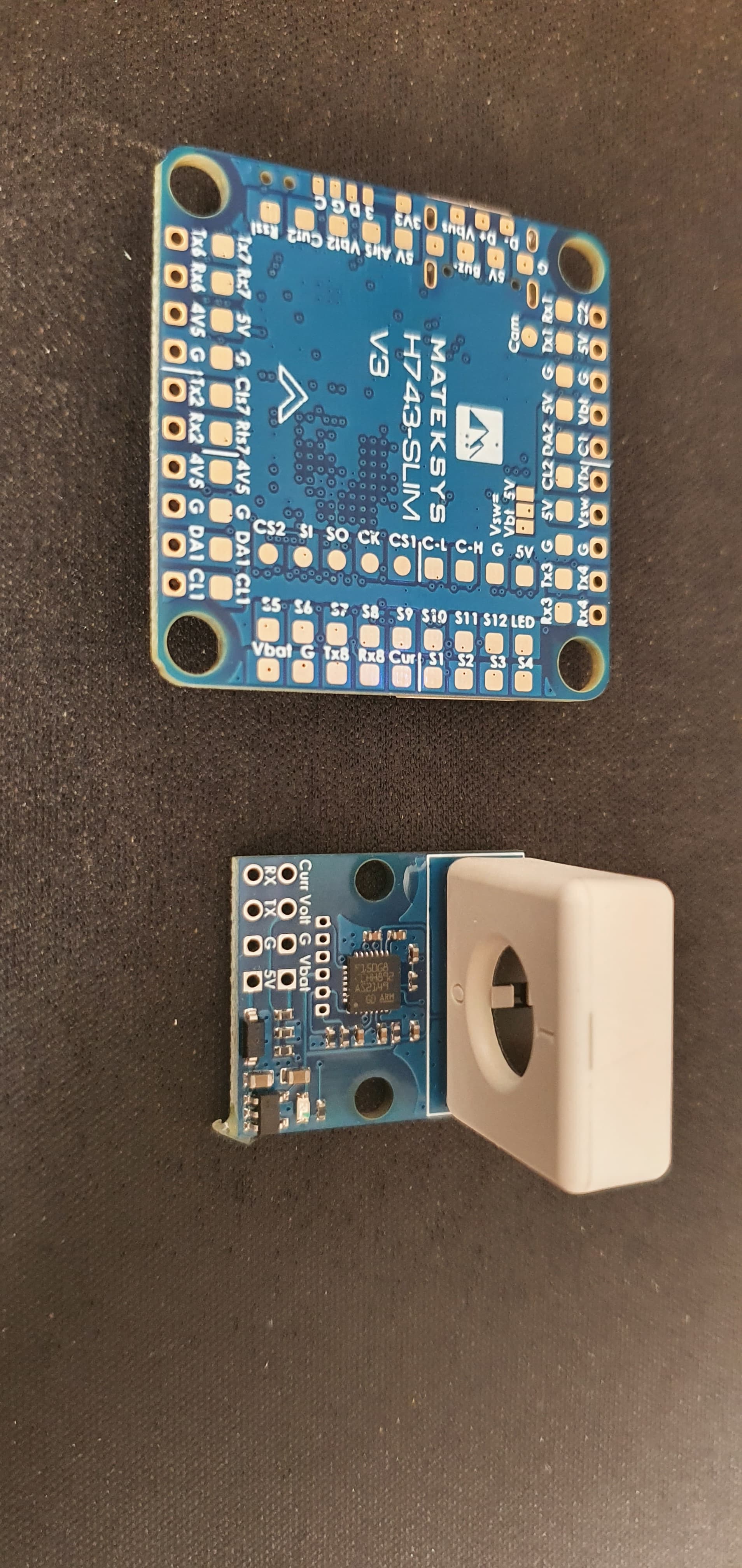
I have been testing these 400W sensored brushless controllers, I have only bench tested them but they are surprisingly smooth. they should be supported directly with ardupilot using the “brushed with relay” motor type. and for £12 each they are very reasonably priced. I have made an adapter to be able to drive them from SBUS.
Hello @geofrancis . I’m curious, did you ever get this to work? Were you able to use the hall effect sensors, input to an arduino, to output AB encoder signals, which were then input to your autopilot + ardurover? I am looking at doing the same thing.
The wheel encoder input worked by just connecting any 2 out of 3 hall sensors directly to the flight controller. since its just counting pulses rather than measuring the time between them, having the sensors offset doesnt matter.
Hello, I built a Rover with an Ibus connection using the SBUS_to_IBUS @geofrancis convector. Everything works and controls on one board, but I can’t figure out how to connect two more boards to make six wheels. Please tell me the commutation