1. SIFT-Based Prototype
In my original GSOC post, I described a proof-of-concept NGPS pipeline that relied on SIFT feature matching against a stitched map. While functional, it generally fails under varying lighting and texture conditions, requires existing database, and its update rate oscillated between 0.5 Hz and 3 Hz.
2. Transformer-Based VPS & VIO
To improve, I replaced SIFT with a learned matching approach. I extract sparse features using SuperPoint, then feed them into a lightweight transformer model that dynamically matches descriptors at inference, achieving high rate output. I paired it with a VIO back-end. This provided local poses at 10 Hz and higher as configured and data inputs.
3. EKF Extension Attempt
Before moving to global optimization, I tried to extend the ArduPilot’s AP_NavEKF3 to fuse both VIO poses and coarse VPS estimates. I modified the EKF update step and made a drop-state measurement model, but the added covariance propagation and measurement updates increased processing and memory usage and triggered watchdog errors. I’m sure @rmackay9 sir might have an explanation for this. I suspect my own code changes introduced some inefficiencies.
In any case, I didn’t work on it further as I was eager to implement offboard estimation.
4. IMU + Optical-Flow + VPS: Optimization-Based Fusion
So finally I resorted to fusing all constraints in a two-stage optimization pipeline using the modified VINS algorithm: one for a local VIO step using High-Res IMU at 100hz + Kanade-Lucas-Tomasi sparse optical flow with output rate of around 20hz and another global optimization step using VPS. The target 4DOF state vector (position, orientation(yaw), and velocity) is optimized over IMU preintegration residuals, optical-flow reprojection errors, and a global optimization problem in the second stage. The optimizer in a fixed-size sliding window provided estimates rates of ≥ 20 Hz on an i7 CPU and RTX 3060 GPU, and tested >10 Hz on Jetson Orin NX 8 GB (inference only).
Altitude and yaw are handled by barometer and compass estimates from the onboard EKF, respectively.
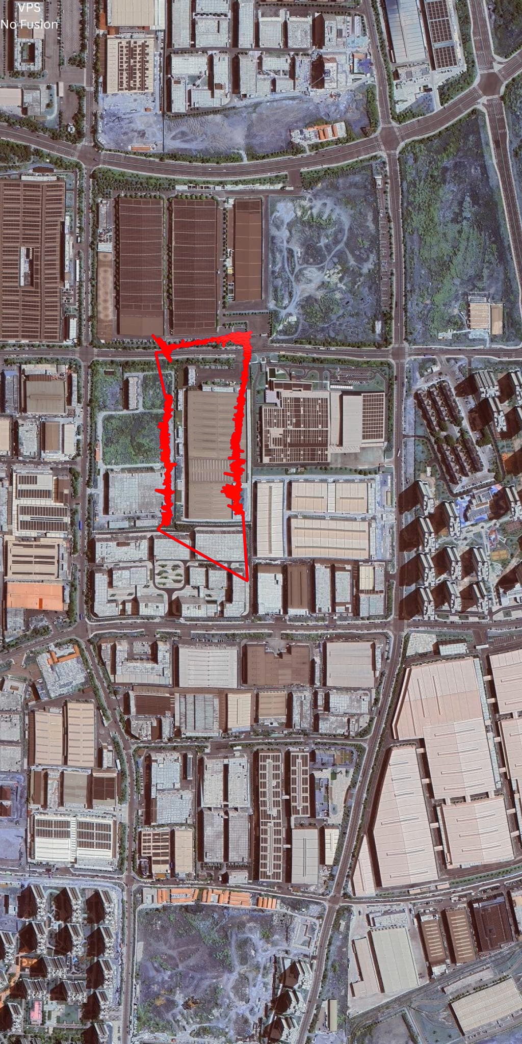


Estimated UAV trajectory at 150 m altitude overlaid on satellite imagery. Left: raw VPS. Middle: VPS + moving average. Right: VPS + Gaussian averaging.
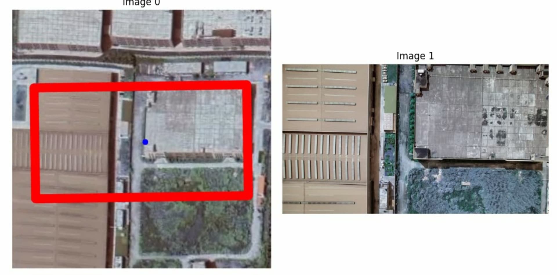
Downward-looking camera footage (×4 speed) used for VPS map matching at 150 m altitude flight.
Click on this to redirect to the Raw VPS estimation inferencing visualization video
5. UKF Prototype vs. Direct Optimization
I also prototyped an Unscented Kalman Filter to fuse VIO and VPS. Although, as expected, the UKF provided pretty good estimates but I resorted to optimization based fusion as … I just wanted to do so : ) The measurement model I designed for UKF is a simple drop state model, considering the input is already compatible with states.
6. Testings and Development
All components run as ROS 2 nodes: fusion_node for VIO, vit_matcher_node for VPS, and ngps_fusion_node for the global optimizer. I resorted to use MAVROS initially as messaging protocol but in final version will shift to native AP DDS. I simulated everything on Gazebo Harmonic and ROS Humble.
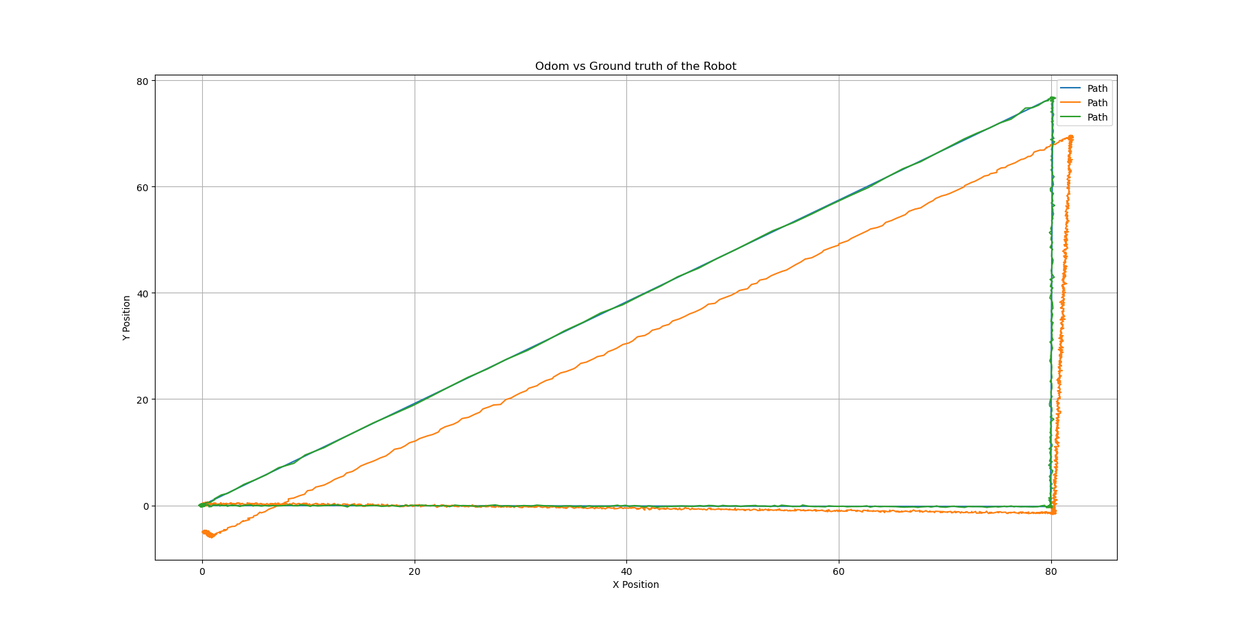


Simulation results: ground truth vs. raw VPS vs. VPS fused with VIO.
A 3-point triangle trajectory simulated in gazebo
The ROS2 bag file for this tests is around 14GBs. I am still figuring out a way to share that;
7. Calibrations
Mainly for hardware, I measured IMU noise and bias and used Kalibr to find the camera-IMU time offset and extrinsics.
8. Hardware Trials
For hardware trials, thanks to @kkouer for helping me with actual flight tests to test the algorithm and providing the dataset for training and optimizations. We are still in process of conducting a safe online HITL tests.
Also @ppoirier has been a huge help all along : )
9. Code & Release Plan
I’m still refactoring code into clean, modular ROS 2 packages and solving some bugs along as I conduct tests. It’s a mess now because of experimentation and development. I’ll push the standalone UKF module along with it. All repositories will be open-sourced in the coming weeks after hardware tests are verified.
I have already open sourced my colab notebooks that contains crude implementation of the VPS algorithm. You can find it on my existing ap_ngps repo.
10. Future Plan
This project exceeded than originally planned timeline because I underestimated the work involved : )
I am planning to use a loop closure algorithm based on traditional descriptors and BoW in future with improved frame alignment and interpolated correction. The main reason for not using loop closure in current implementation is that at high altitudes, the accumulated drift can reach tens of meters compared to in centimeters in case of indoor positioning and estimation. The loop closure could cause large discontinuities in the AP’s EKF if fed directly and sure it won’t be good for the drone. To avoid those jumps, a simple transformation + interpolation, followed by a simple low pass filter might help in blending overtime.
Apart from this, I am confident that using SFM, we can build a full fledged SLAM with a larger baseline stereo for mapping purposes with higher precision.
Most of the existing solutions out there have some drift involved in their non-GPS positioning but I aim to nullify that and make it really robust. It still have a lot of work required to make it as I want but it’s really a learning roller coaster.
Thanks : )