I’ve been trying to configure a Throttle Based Dynamic Notch filter recently, and wondered if anyone would be able to review these logs for me and tell me if I’m moving in the right direction/doing things correctly. I work in education, so unfortunately the hardware I’m flying this on is quite dated, but I believe the notch is working so far. I’m flying a Flamewheel 450 type frame, and using a Pixhawk 1 “clone”. 5000mAh 3S battery. I’ve been following the instructions on this page Throttle Based Dynamic Notch Setup — Copter documentation
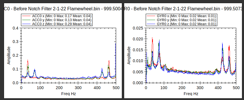
If I’m doing this correctly - one of my questions is why I see two peaks in the FFT analysis - is this a “harmonic” of the motors?
You will see I first tried to use the notch filter at one peak, but then thought perhaps that was incorrect because of the results. I then tried it on the other peak, which seemed to follow better what was on the wiki page. The last log was in preparation for the last section of the wiki page - dynamic flight, though I have not yet gone beyond that point.
Here are my logs, progressively moving through the wiki instructions. Sign in to your account
To me it looks like that first peak is around 39hz.
I also suggest you look at the vibrations on that frame. If everything looks good, consider soft mounting the FC. You’re not getting any clipping, but the levels are higher than desired.
Hi Allister,
Thanks for your reply - I guess I’m a bit confused. You say it looks like the peak is about 39Hz, but when I look at the FFT for the “Before Notch filter…” log, it looks like the first peak to me is centered around 70Hz? I’m also not clear on if I should be focused on the ACC data graph or the GYR graph, though they look pretty similar.
Am I missing something on the graphs to get the INS_HNTCH_FREQ of 39 that you mention? Thanks.
I appreciate the note about vibration as well - the FC is soft mounted right now, but could probably do with a better mount. I have a similar aircraft to try this process with soon which has a better mount - so I’d imagine that will improve things all around.
Oh, I also was going to ask how one can tell which “peak” to focus on when two are present like on my aircraft. The goal would be to get rid of both of them?
The screen shot doesn’t show it but when I mouse over the first red peek on the Gyro graph it’s giving me a value of 39hz. However looking at your screen shot I can see why you picked the values you did. Based on your graph I would have selected the same as you. Yes, you look at the first noticeable peak on the gyro graph. It won’t necessarily be the highest.
I notice the amplitude values on your graphs are also different from mine. Have you updated mission planner recently? I do recall those changed at some point.
Those old DJI frames are floppy. Especially the clones. I had to go overboard on the mounting of the FC on my F450 to get the levels in check. I ended up using an open cell foam. It’s ugly, and the levels are still high, but it flies well. Make sure all the mounting hardware is secure. Double check you don’t have any wires hitting or restricting the FC damping.
I’m going to try graphing this on another computer to see if the installation I’m using here (ubuntu) is causing the problem.
Okay, seems the ubuntu install of MP is having an issue with FFT plots. So don’t make the changes I suggested earlier. Those numbers are wrong.
I looked at your before, and 60hz post notch logs. Those look good to me. In that graph you have INS_HNTCH_FREQ set to 70. You could maybe move that to 65, but honestly it probably won’t make any significant difference. When you compare the amplitude of the before and post graphs you’ll see there’s significant drop.
When you graph the post notch, you’ll see a peak on the gyro graph around 21hz. Don’t worry about that one. I can’t remember the exact reason, but don’t worry about the ones below ~25hz.
I just looked at the post 136 hz. The post 60hz settings are better, go with them.
As for my earlier posts with the wrong graphs, I’ll leave that up. Hopefully one of the smart people can tell me why my graphs came out so far off. Sorry for the confusion.
Thanks for the log review, Allister. I’m glad you were able to get some confirmation on the FFT plot values. That is strange that your ubuntu install is having those issues.
But I’m a bit confused on why you mention the 60Hz settings are better. When I look at those FFT plots, compared to the pre-harmonic notch plots, the 60Hz dynamic notch seems to have quelled the peak at about 136Hz, but a peak remains at 60Hz and I get couple other small peaks, so I end up with more peaks overall. However, when I look at the 136hz plots, it appears to have nearly eliminated an entire peak, resulting in less peaks overall in the plots. Wouldn’t this be more of an improvement? I’m wondering if the 60Hz is a frame resonance issue or something similar that would be better suited to a static notch.
I’m totally new to this process, so please forgive any misunderstandings.
Thanks for the tips on trying to improve vibration levels on the frame. My FC is also mounted on some of the DuBro vibration dampening foam to get the even close to acceptable levels of vibration right now. A new frame is on order - fingers crossed it arrives soon!
It was because of the amplitude. The 136hz plot had a smoother line, but when look at the amplitude of the values the 60hz plot was overall significantly lower. If memory serves, by a factor of about 10. Also the 60hz settings took out that first major peak.
Agree with @Allister that your filter setting are good. A static notch can work well if there is a lower peak that is not a harmonic of a higher one. Let’s say at 45Hz and you had your 65Hz and the Harmonics of that. You could use a static notch to attenuate the 45Hz mode.
Regarding filters will too low of a notch frequency, in the early days of the Dynamic Notch filter I tried one at 25Hz and it effected control of the craft adversely. That’s what I was getting at in the linked post.
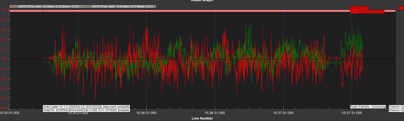
You do have quite a bit of noise on the Rate controller and motor output oscillation.
@dkemxr Thanks for your reply. I have a lot of other questions, and really appreciate the help - especially spending your time helping me troubleshoot not-very-good hardware, haha! Just to make sure I’m clear on what you mentioned about the notch and static notch, the following settings are appropriate?
INS_HNTCH_ENABLE = 1 to enable the harmonic notch
INS_HNTCH_REF = MOT_THST_HOVER value
INS_HNTCH_FREQ = 68HZ (basing on the GYRO Graph - am I supposed to look at both GYRO and ACC?) - Is there any “rule of thumb” for determining which peak is most likely to be motors besides the 100Hz/200Hz for small/large copters mentioned in the wiki?
INS_HNTCH_BW = 34HZ (68/2)
Since in the pre-harmonic notch log, I have peaks at about 68 and then again at 135ish, could I assume that this is a “harmonic” (68x2=~135), and could be filtered using the
INS_HNTCH_HMNCS = 1
?
In my post 60Hz Notch log, I still have a bit of a peak around 65Hz after setting that notch - would I then want to set the INS_HNTCH_ATT to be a greater value than default, or are the levels I see post 60Hz notch normal/acceptable?
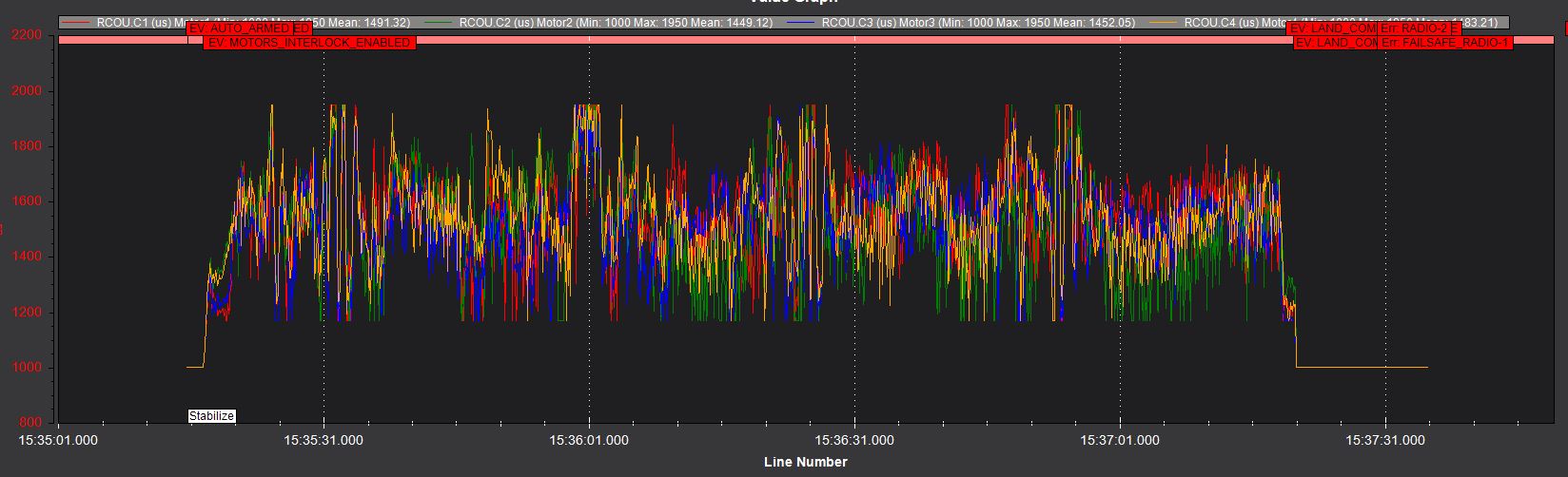
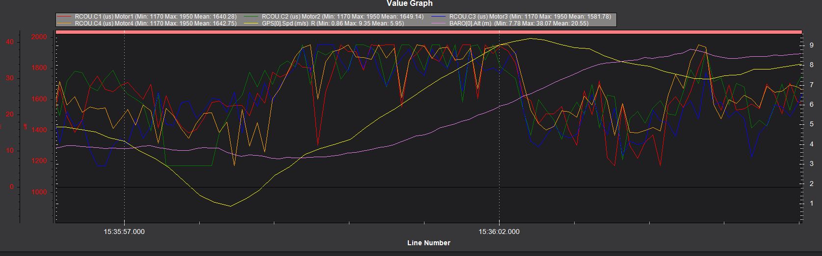
Thanks for pointing out the motors maxing out and the noise on the rate controller as well. The goal is to get this notch set up to allow for a better tune, which won’t fix the motor maxing issue, but hopefully will help the noise on the rate controller.
This is all correct. Gyro graph only as the filter is not active on the Accels. The peak for motors can be roughly determined by the RPM shown when you mouse over a peak and then figure it from your motor kV and voltage. But the range you suggest is in the ballpark for small and mid size craft.
From ~65Hz you have harmonics at ~130Hz and ~200Hz so I would leave this at default (3) which is the bitmask for 1st and 2nd.
You could try that but attenuation beyond 40dB may not make much difference.
Thanks for the tips, @dkemxr. I’m now trying this on (hopefully) slightly better frame. It is the HolyBro S500, one of the Arducopter reference frames. I have had horrible luck with the Arducopter S500 reference frame “presets”, which may be a separate issue, (I just went back to the firmware default PIDs and got it flyable from there), but I have flown with the logging enabled, with the following result. “Pre-Notch Filter S500”. I’m planning on targeting the notch at 84Hz, based on your suggestion of peak identification based on motor RPM. These are 880kV motors, on a 3 cell battery (12v) would spin at approx 10,000 rpm, so in hover flight, about mid throttle, I’m at 5000 rpm. https://usu-my.sharepoint.com/:f:/g/personal/a01416515_aggies_usu_edu/EoZjC0_LEFRJu0Wb2KFv0mYB-VRIoSr6h7eGipBN8vuO3Q?e=4ssY3U
Does that peak target sound reasonable?
How do you figure out the harmonics to be 130 and 200? I simply have no idea how this is calculated and would like to learn.
I have flight logs of both with and without the S500 presets in the same folder linked above as well, simply trying to hover it in those logs.
You need to enable INS_LOG_BAT_MASK (1) to get a good look with FFT. And for now I think you want to be on the Preset Parameters.
Harmonics are just a multiple of a fundamental frequency. So if the Fundamental Frequency is 66Hz the 1st harmonic would be 2X65 or 130Hz, 3rd harmonic is 3X65 or 196Hz.
Sorry @dkemxr , I didn’t explain well. The log titled “Pre-Notch Filter S500” does have the INS_LOG_BAT_MASK parameter enabled. The other two logs do not, so I was referring to that one when talking about the peaks, etc.
Actually I think it was my mistake and looked at the wrong parameter file. I can see that you do indeed have batch logging enabled.
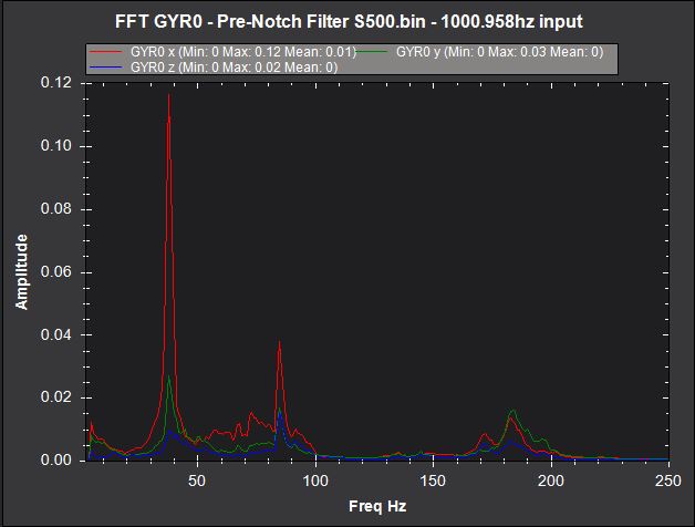
So this is an interesting graph:
There is a peak at 38Hz another at 85Hz and a 2 closely coupled ~170-185Hz. 2 approaches could be taken here. The 1st with a Static Notch at 38Hz and a Dynamic Notch with center frequency of 85Hz. Or a Dynamic Notch with a center frequency of 38Hz and hope the higher modes are attenuated. I would try both approaches and see which one works best.
It does indeed. I wonder if there is something going on with the MP versions and this isn’t right. It won’t update for the reason Mr. Oborne gave in the MP thread.
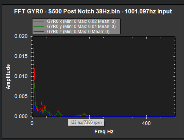
Took me a while to get back to this, but I ended up centering the notch at 38Hz, as you recommended, @dkemxr . It looks like it worked very well. I have not yet tried the other approach you mentioned. Thank you again for the help.