TF Mini Plus for object avoidance

Good day all

Got myself a TFmini Plus and have been working to get this going on a Hexcopter, Pixhack V3x.
Copter 4.03 FW.

Followed this doc:

But I found this discussion on the this forum
TFmini plus ,avoidance and arduino
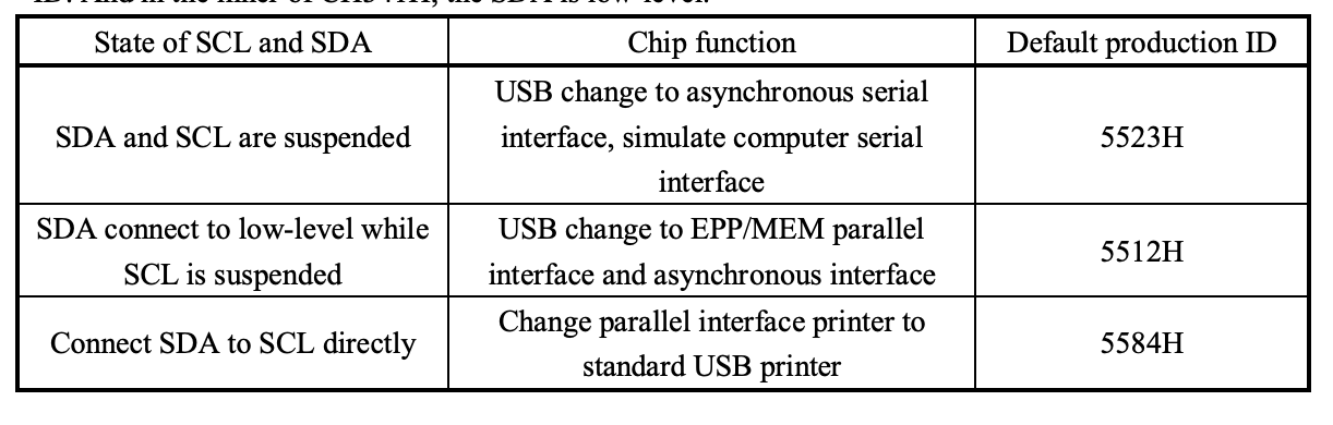
which seem to suggest that TFminiPlus will only work with I2C comms.
The date on this discussion was Oct 2019 and the release notes had an entry also around
Oct 2019 about TFminiplus support

Copter 3.6.11 01-Oct-2019 / 3.6.11-rc1 16-Sep-2019
Changes from 3.6.10

  1. EKF and IMU improvements:
    a) IMU3 enabled by default if present
    b) IMU3 fast sampling enabled by default on Cube autopilots
    c) EKF protection against large baro spikes causing attitude error
    d) EKF origin fixes (consistent across cores, set externally only when not using GPS)
    e) EKF logging of 3rd core
  2. Minor enhancements:
    a) Land mode supports heading requests (ie. ROI)
    b) Support Hexa-H frame
    c) MatekF405-STD binaries created
    d) Benewake TFminiPlus lidar support

Can I assume that this does not mean that from 3.6.11 upwards there has been additional
support ? i.e. it will still only work with I2C?

I would just like to confirm that my interpretation is correct which means I will have to get the I2C
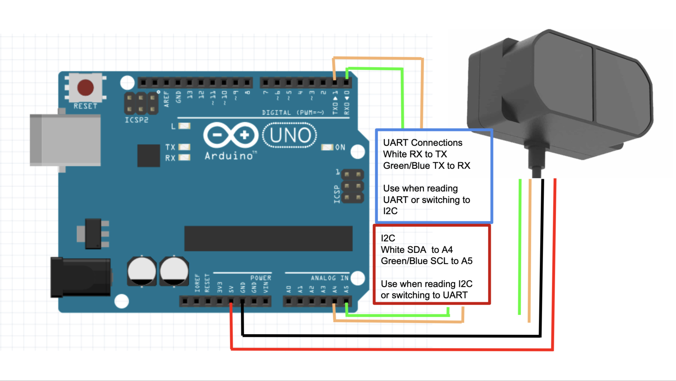
and not waste any more time trying to get the UART version to work ? Unless ofcourse I use
an arduino, which is eventually the idea, but for a start I thought I would just use a single
LIDAR directly onto my FC.

Many thanks
John

Good day all

I am not going to answer my own question , simply because I do not have the answer.

What I am going to put in here , is some assistance , if you will. Just incase some-one else
is having similar problems.

OK, so here goes …
SO you buy your TFMiniPlus to put object avoidance on your drone and you want to use the FC
to interface directly with the sensor instead of going via a companion computer. So you read up
and many docs seem to suggest that you can use the TFMiniPLus via the UART port on your FC.

IT would seem ( and this is what I was trying to confirm ) that the software only supports I2C comms
to the TFMiniPlus.

But thats cool, you say to yourself. I shall just re-configure the TFMiniPLus to talk I2C. Then you look
in the manual and find nothing to this effect. You are about to contact your best supplier to buy an I2C
version of the TFMiniPLus but before you actually do that, you contact Benewake support. Turns out,
the manual that you were working from , was incomplete. YOU CAN actually re-configure the TFMiniPlus to communicate on I2C. There is a catch.

To configure the TFM , you use software that connects to the TFM via USB/RS232 adaptor. (UART) and after you issue the command to put it in I2C “mode” , the software no longer plots the data that the
TFM is outputting. SHould you simply cycle the power ( reset ) it goes back to UART mode and the software can plot the data. If you SAVE the change, it can no longe rplot the data.

I see there are suppliers that sell USB/I2C adaptors. Maybe thats part of the answer ?

Anyway, long-and-the-short … you re-configure the TFM to I2C mode … and off you go.

Best

1 Like

The easiest is to put the TFMINI in Pixhawk mode , so it is sending clear text altitude and use it as the standard lightware serial sensor within mission planner

1 Like

Many thanks for this suggestion.

What I shall do is follow your advise and get it going as a fisrt step. I can get familiar with the TFM+.
As a second step, I would also like to get my hands dirty with Mavlink. The way I would like to do it
is to then interface more than one TFM via companion computer ( Teensy 4.0 ) to my FC.

You do stuff like this everyday !! But to me it feels like Neo sitting infront of Morpheus holding the BLue and the Red capsule !!!

Appreciate you taking the time to help.
Regards

1 Like

I changed the TFM Plus to I2c mode and save it. The USB - I2C adaptors(CH341A chipset) ready, the default address 0x10, there is no response when i enter the version command 5A 04 01 5F or distance acquire 05 00 01 60. What software recommend to use and how to do a simple query distance thru i2c mode?

Thank you

Good day

I did not use a USB-I2C addaptor but I wrote some code on an Arduino Mega to access data on the TFM+ and also to do setting-changes.

Yes, you have to issue the “Obtain data frame” command 5A 05 00 01 60 but look at the spec again. It instructs the user to wait 100msek before reading data from the device.

Best

Actually I never worked with that chip but it really looks interesting
@patrickelectric I see you blogged about it, https://patrickelectric.work/blog/2018/ch341a-dongle/

Could you comment on correct usage?

Hi!

I can give my 2 cents about this matter, but please take everything I will say with a pinch of salt.
First, my blog is something that I quickly write it down to help a future version of myself, so sorry for how poor everything is presented there.

From what I know, you can configure the CH341A using SCL and SDA pins, the PID will change after the configuration is done:


5512: I2C and SPI
5523: UART
5584: The old parallel interface

I’m not sure if the newest kernel supports it, but the last time that I tried it it was necessary to compile and run some modules to make it work, you can check the links in my post and a simple list of commands to help you.

1 Like

For what it’s worth I have a similar setup Pixhack V3, Copter 4.03 and two TFMiniPlus. I have switched the TFMini plus to i2c using this lib TFMini-Plus and an arduino. I am using the i2c splitter that came with the Pixhack. One thing to note on that splitter: the SDA and SCL lines are twisted compared to the way the TFMiniPlus is wired from the factory.

The setup is working fine, the address in arducopter is written in decimal ie. the default address is 16.

However, I have encountered another issue. I am using FrSky telemetry passthrough and when the Lidar is working the telemetry is sporadic and eventually stops. This does not affect telemetry via the 3DR radio.
Has anyone encountered a similar issue ?

Good day Emmanuel

From what I understand from you is that the SDA and SCL lines on the splitter is swopped around?

Could I ask you to send me some pictures in this regard to show clearly what you have found because I would like to take this up with CUAV.

You can use my email
jlongland at webafrica.org.za

Best

So far so good…

3 TFMiniPLus LIDAR sensors reporting their data to the flight controller at 20Hz.
Teensy 4.0 seem to be coping quite well.

Ultimately I want another 2 sensors : one for “UP” and another for “DOWN” but with the lockdown
I am no sure when I will be able to buy them.

I did not write all the code myself and because it is my first Mavlink project, I had to rely on the project
by @ppoirier for the mavlink-part of my code. Thanks ! Maybe oneday someone can benefit from one of my projects in the same way. Just for the record - I elected not to use the TFminiPlus library but instead wrote my own code.

Now I need to make a nice case on the 3D-printer for this lot and mount it on the drone and wait for locldown to end so I can take it out for a test-flight !!!

Best !

1 Like

Hi all, I have been messing with this al my self and I have made a mode switching sketch for the Arduino based on budryerson original work for the TFMini Plus, I have also tweaked his I2c reader as well slightly to allow address changes art the start.

The code is https://github.com/MadRC/TFMini-Plus-I2C

Here are zipped files for it as well, the git will be updated to make it a little easier https://www.dropbox.com/s/ko57wpftgdn2b9d/TFMini%20Serial%20to%20I2C.rar?dl=0

These have all been very quick and messy but do work, basically you need just an Arduino UNO.

The main purpose of this was to easily allow changing mode for use in Ardupilot and PX4 with out having to understand the code.

These files have been tested on Arduino UNO and do as follows.

Serial Read

Simply reads the TFMini Plus when in serial mode, no changes made. this uses pins 0 and 1 as per the Uno serial ports.

SET I2C

This will change the communicationd mode from UART to I2C on the default address of 16

I2C Read

This is allow you to change the I2C address then read the I2c output, this is configured for Pins A4 (SDA), A5 (SCL) as per wire.h.

SET Serial

This sets the port mode back from I2C to serial.

How To Use

You Will need to install the TFMPLUS and TFMPI2C Librarys for use these files, these can be found in the libary manager or they are also included here too.

To change from UART to I2C

Verify and upload serial read sketch to arduino, reboot.
Connect via correct ports for communication type (for serial to I2C connect on pins 0 & 1) Power on and open serial console from tools menu and verify connection by seeing data from sensor.
Verify and upload SET I2C sketch to Arduino, reboot.
Power on and open serial console from tools menue and you should see it complet to switch

These codes where quickly made and tbh are not a tidy modifications but work, I will tidy in time.

3 Likes