The new version of my rotating lidar uses a Benewake TF02-pro lidar.
It does not rotate anymore, but rather oscillate using a stepper motor and a poti.
I could not use a 360° rotating lidar on my rover anyway and the TF02-pro is too big to fit over the mirror of the previous version.
I also figured out how to correctly use the “obstacle_distance” mavlink message and why it did not work before. 115200 bauds were just to slow to handle the 72 value array. With the baudrate set to 1500000 (I just went for max, lower values may also work) everything works as it should. The mechanical setup allows for maximum 120° field of view and can be configured for lower values and therefor faster scanning.
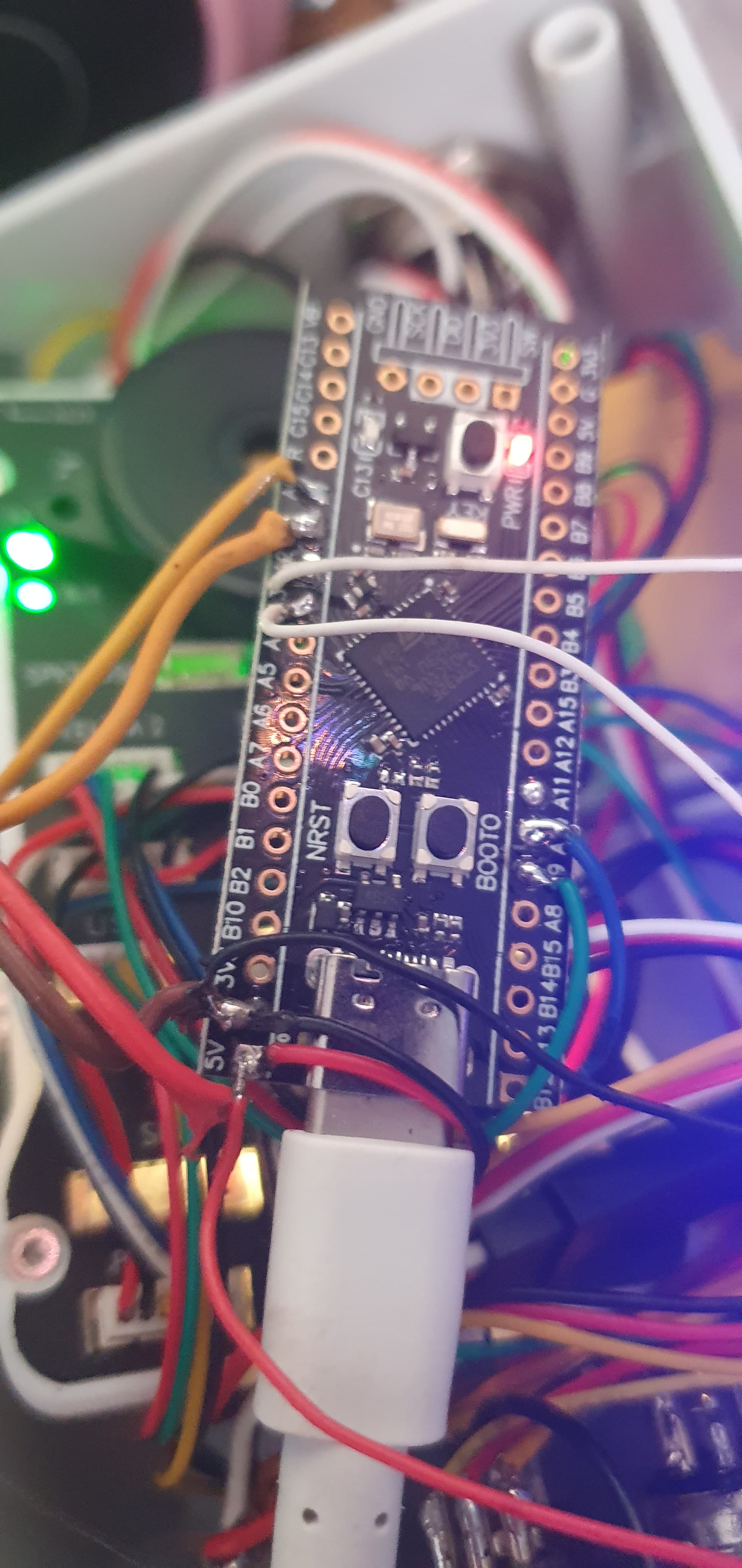
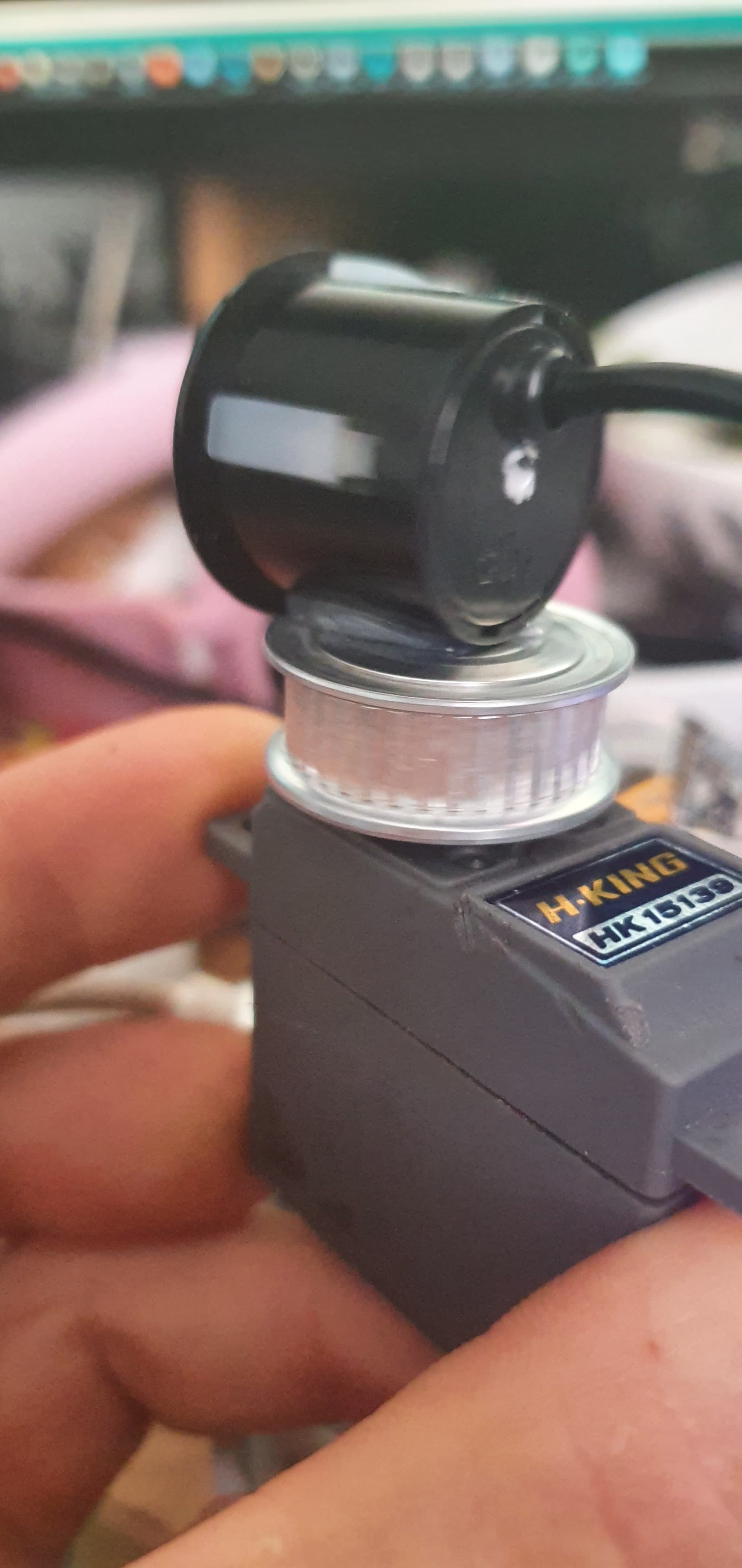
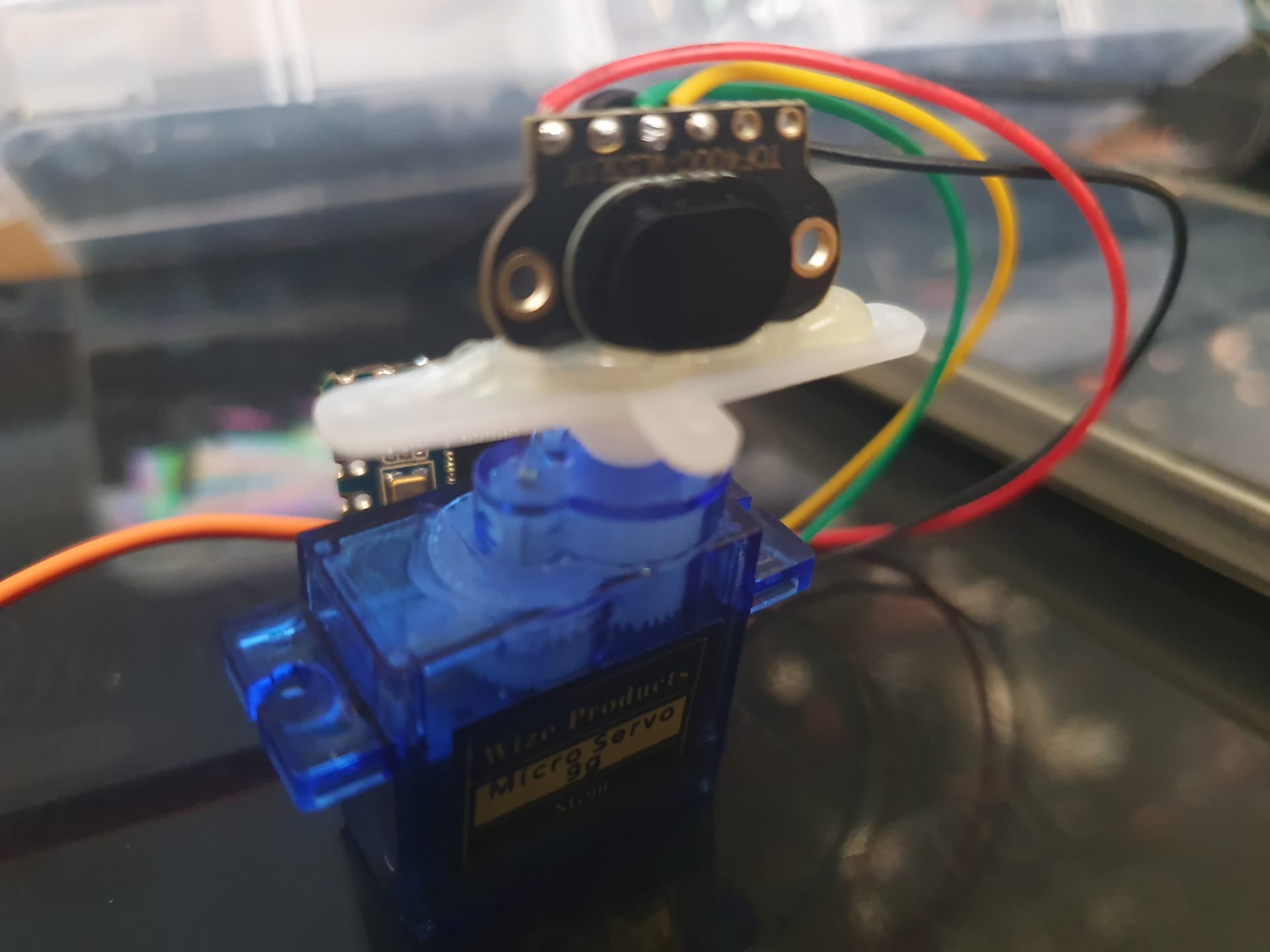
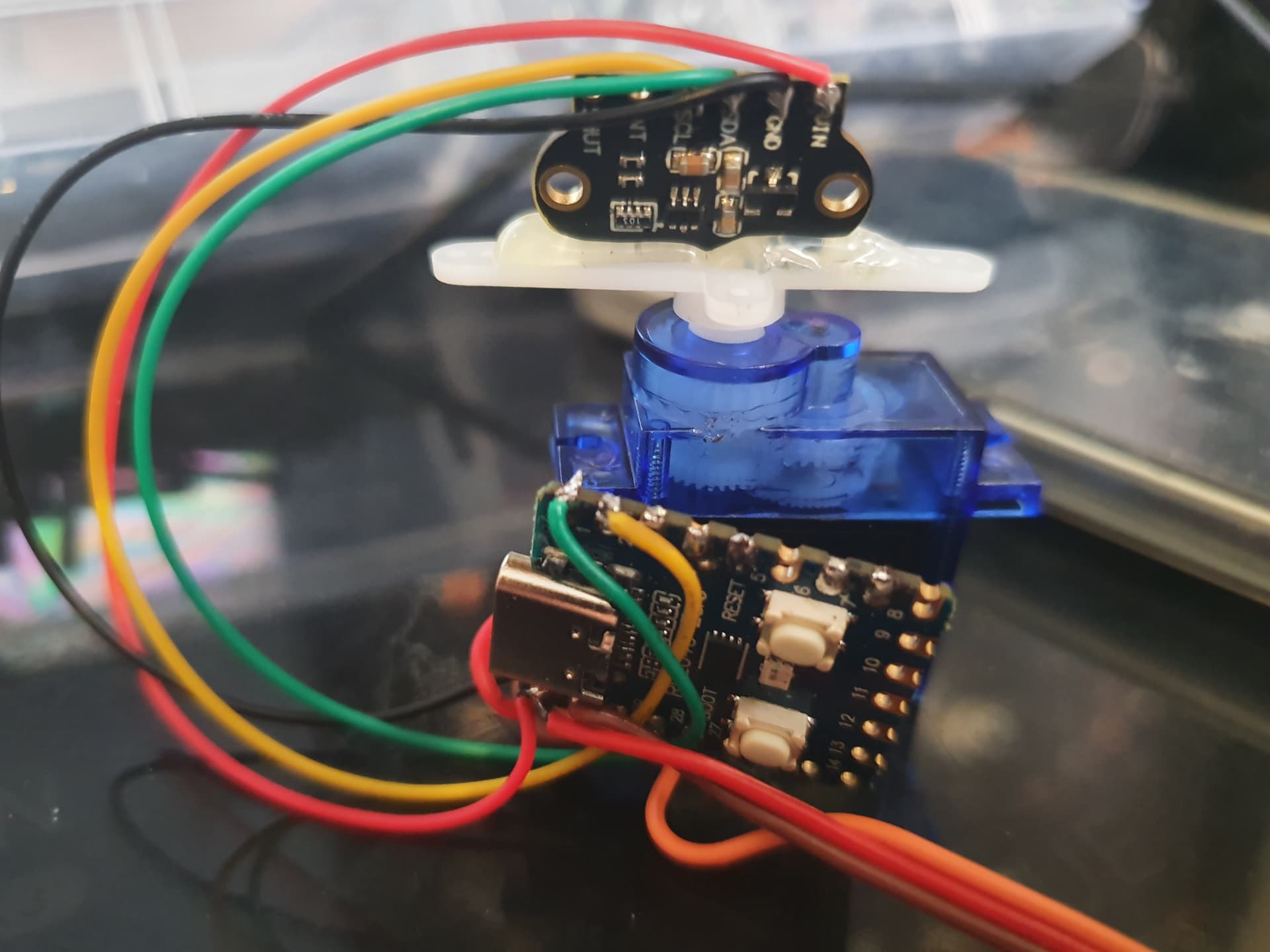
Pictures, a short video of just the lidar moving and the arduino sketch for the blackpill:
@count74 I have a version of your code up and running but using a servo and sonar rather than a stepper and lidar, the plan is to eventually use it underwater.
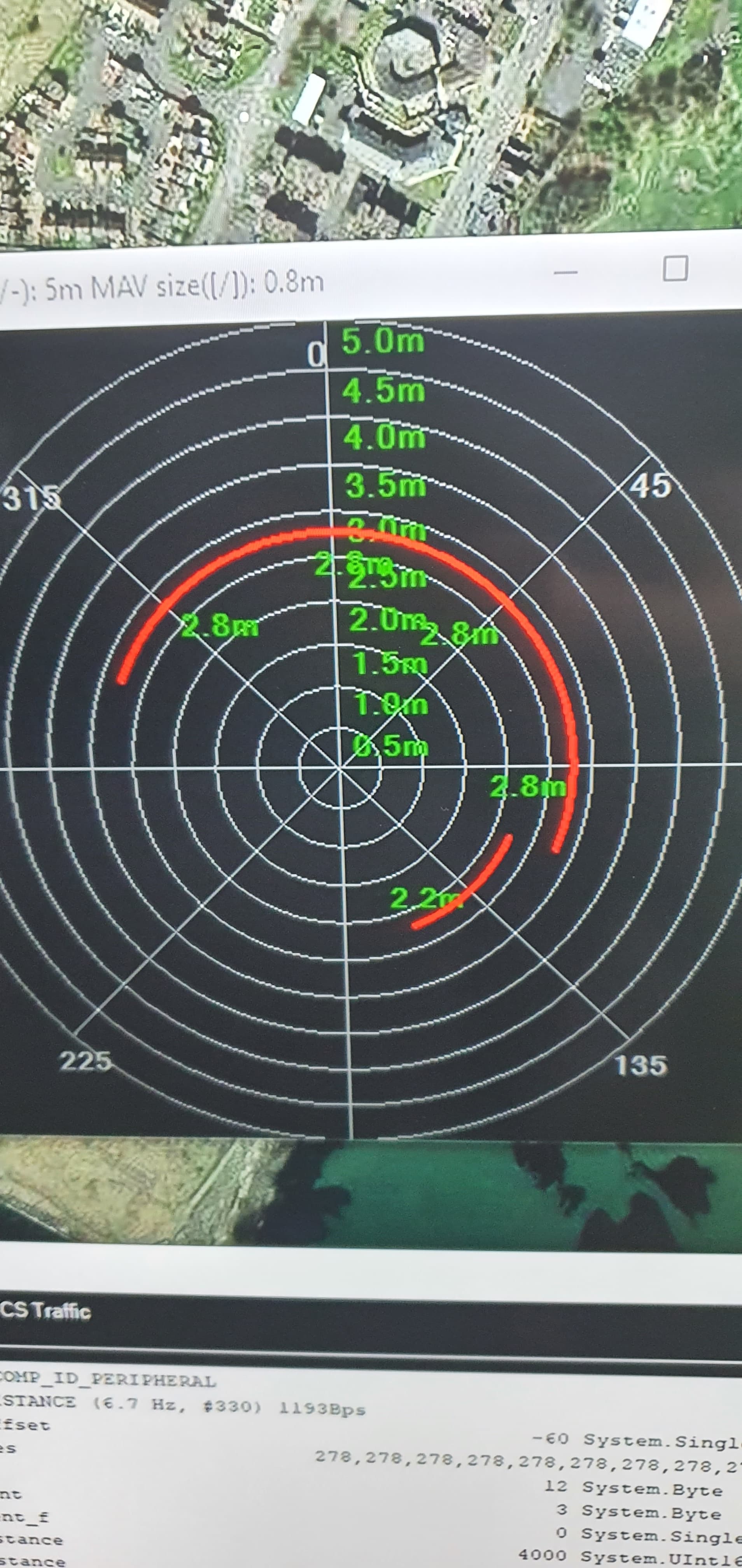
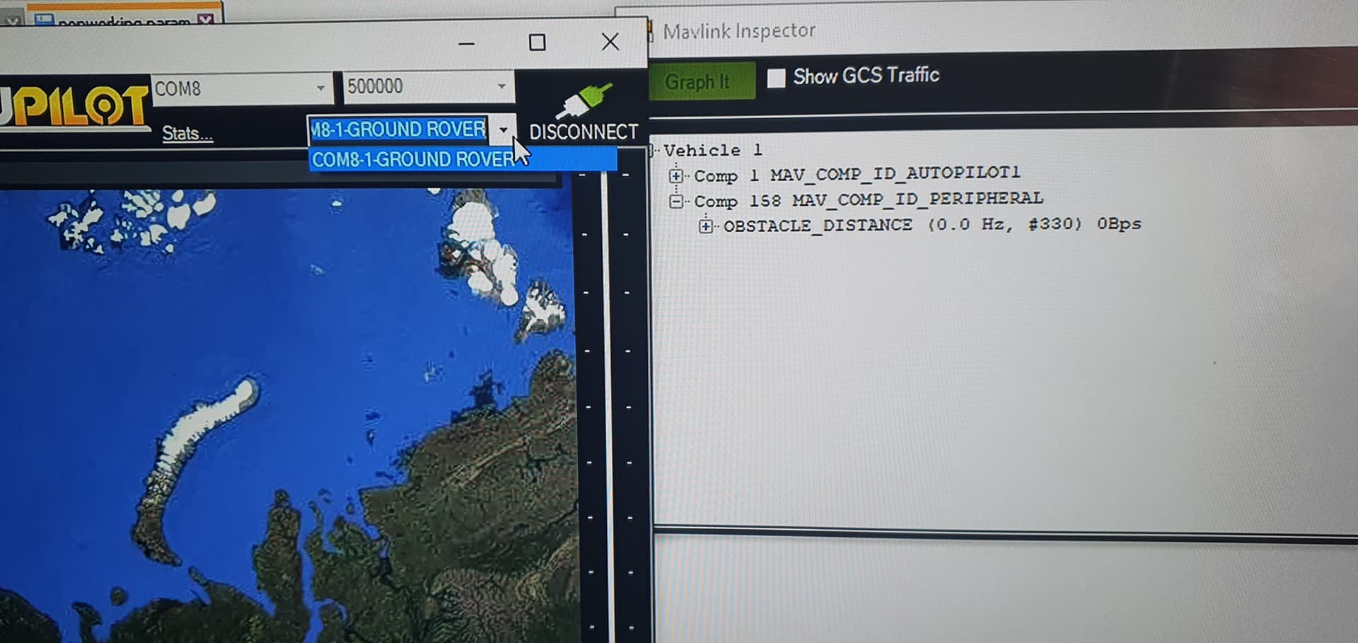
after a lot of messing around i have something working but i can only get the 8 segment display on mission planner, how do i get the 72 segment display?
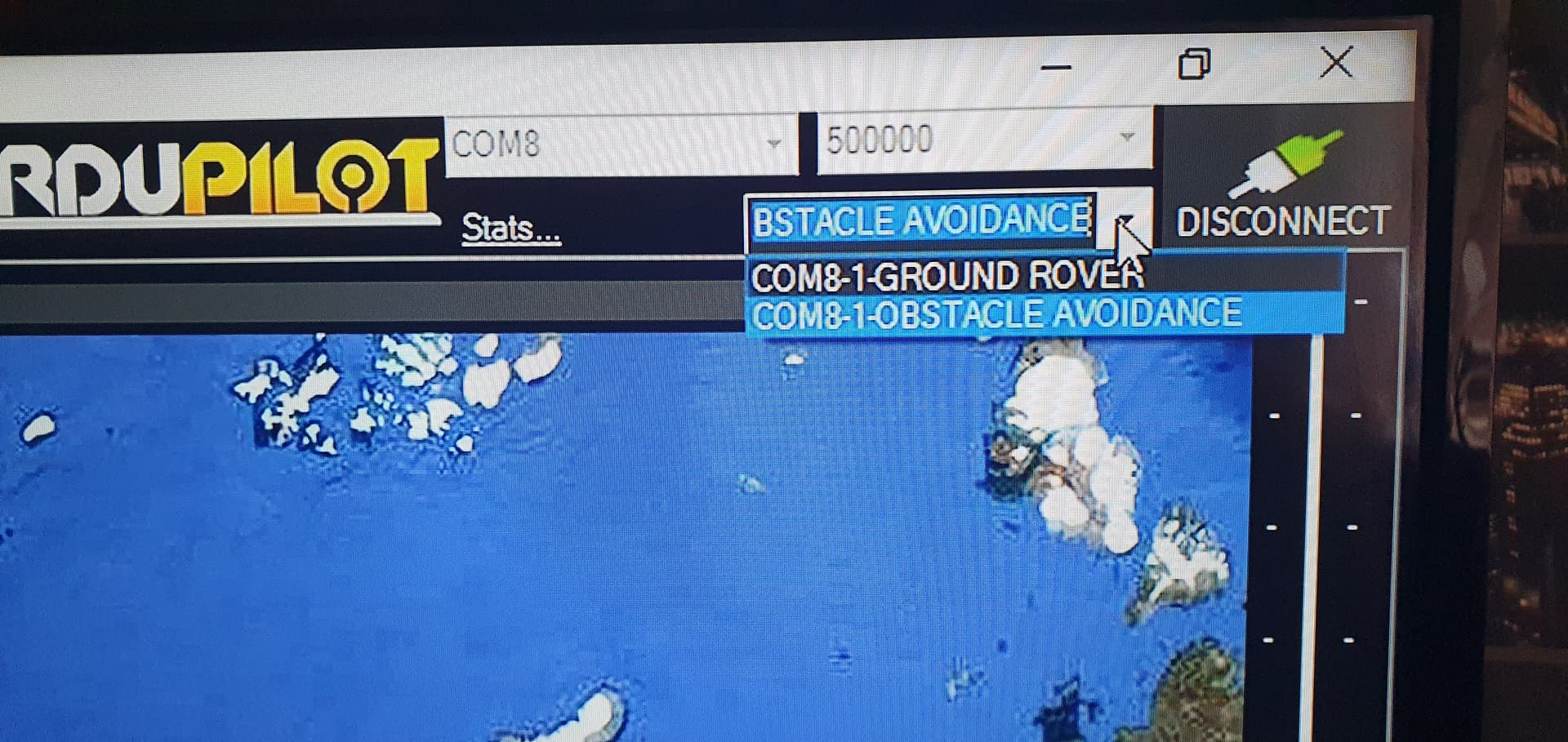
Got it working, It needs to broadcast a heatbeat then you can select that mavlink component in mission planner and you will get the high resolution view.
I keep it there so i can drive the servo using alternative inputs, i can tie it to something like the camera gimbal so it ranges where the camera points, or just manually control the scan using the rc. my sonar tops out around 10hz so 72 slices means im limited to around 1 scan every 7.2 seconds. accuracy is more important to me than raw speed. I have 5x fixed underwater sonars for close range detection.
I also have a radar im planning on adapting to this system for use above water.
What would be nice is to request data from the flight controller to alter the scan profile dynamically, so when the boat is under 1mph do a full 360 scan to cover all sides but reduce the scan field as speed increases so it would drop from 360, to 180, to 120, or even 60 degrees at full speed.
another idea would be to limit the left and right scan field as the boat rolls so its not scanning the surface of the water for false returns.
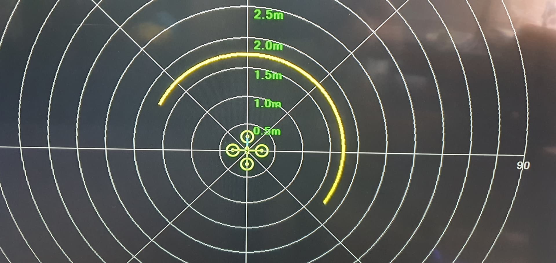
Does your setup really fill all 72 segments? With my lidar/stepper setup, the scan range is limited to 120° and the FOV of the lidar is ca. 3°. So I can fill 120 / 3 = 40 segments with distance data. I could overlap the scans a bit and the FOV of the lidar is actually 2.7°, if I remember correctly. But the small gaps do not really matter for a moving vehicle where the perspective for the sensor changes all the time.
Your sonar probably has a greater FOV and the servo does 180° max. So take the 180 / SensorFOV = number of segments. And if you use microseconds instead of degrees in the code, you can move the servo in smaller steps and even beyond 0/180 degrees, if your servos allows that.
Yes, false positives from the ground are quite annoying. If you drive on a sports field and place a few objects, it is all fine. But as soon as there are slopes, vegetation, curbs it goes all crazy.
I did see that it wasnt always filling every segment, took me a while to figure that out as i was still working out timing issues, I have increased the scan field to 180 degrees and set the resolution to 2 degrees to make sure it could fill them all for testing. The sonar does have a much wider fov when dealing with flat surfaces but when dealing with smaller objects at long range the detection range is much narrower so having fine slices is still useful.
I want to use it to look for fish as well as path planning.
Another idea was to mount it on a gimbal for tilt and roll to prevent ground detection, it doesnt have to be fast or high resolution so servos would work fine.
the stops on the servo dont really matter its all about how many sections the pot is split into.
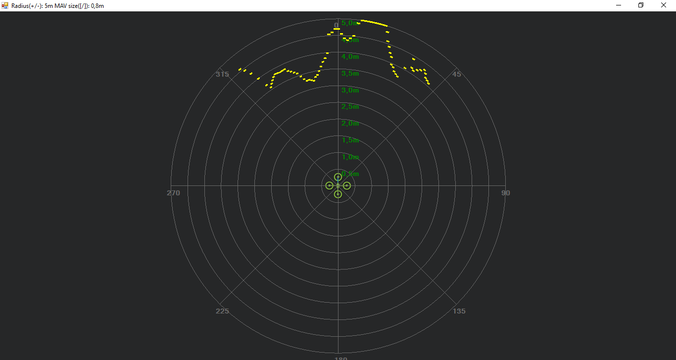
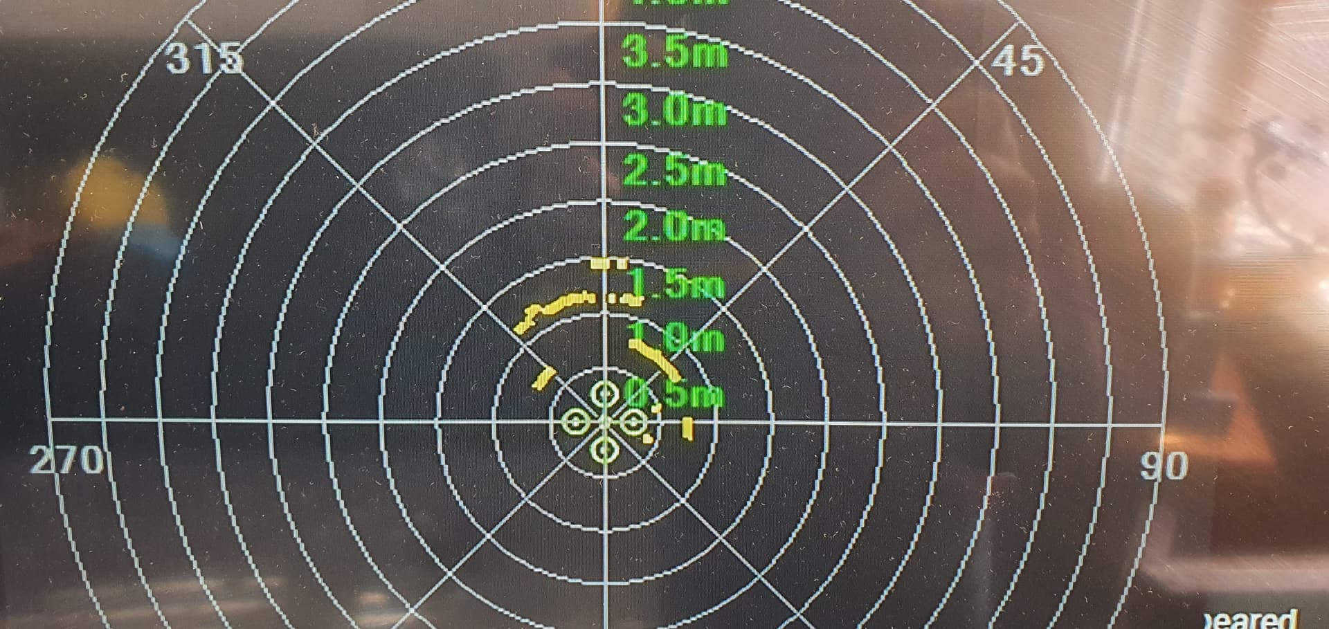
I changed the FOV to 360 and resolution to 5 degrees, then split the pot into 144 sections to get the math to line up. giving me 72 slices now all filled. The key was getting the end points bang on or it wont use all the slots.
I have 3d printed a 2:1 servo gearbox to turn my 180 servo into a 360 servo, if it works il either get a proper robot feedback servo or a 1.5 turn sail winch servo.
I have burnt one out before testing a setup like this, running them too fast and not giving them time to stop at the end before the change direction really causes them to heat up fast.
there are some tiny stepper motors out there, I will look into adapting one.