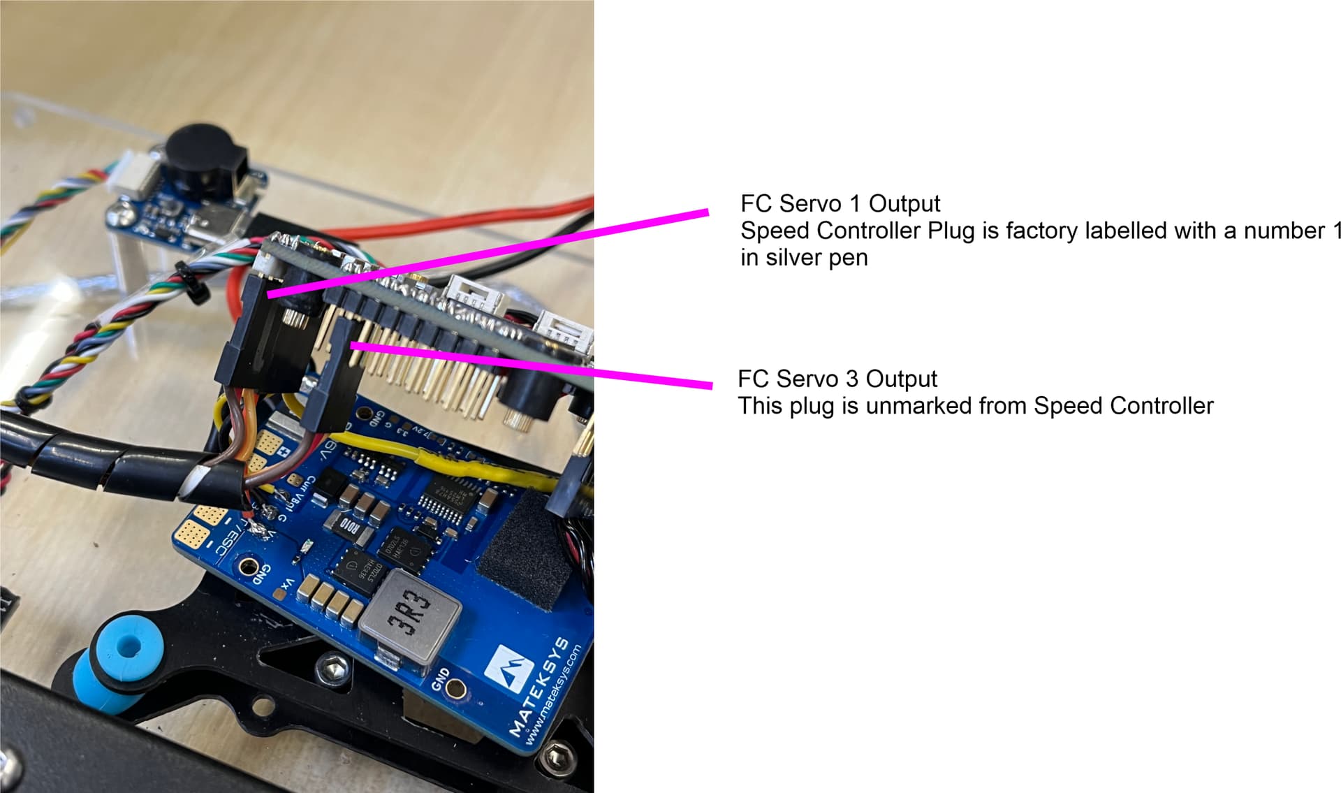
Finally got a servo output from FC with thanks from @Yuri_Rage .
Skid Steer Rover
Moving on I carried out the following tests with strange results.
Again, any help would be appreciated.
While I appreciate the effort you made to make videos, they are hard to decipher and probably a bit of wasted time. It’s obvious you are getting 4 wheels turning during the motor test, which is not correct. Beyond that, the videos don’t help much.
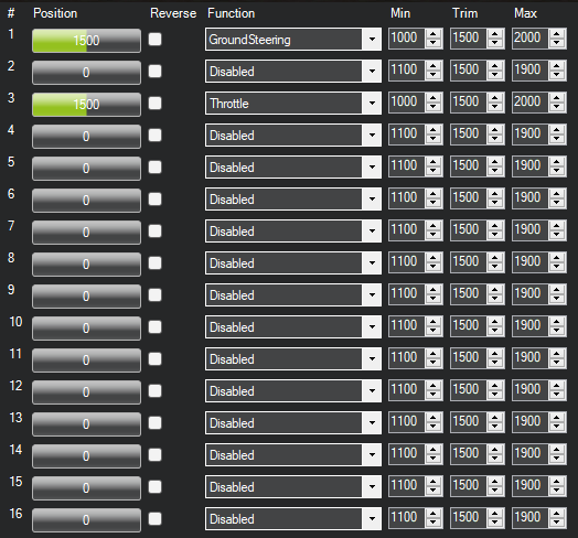
Post a screenshot of your servo output page like this one (but with your settings):
It might also help to attach a copy of your current parameters from the full parameter list page as well as a description of the motor controller you’re using and how it’s wired.
Videos were to show the different wheel speeds from each side. Not sure that is normal.
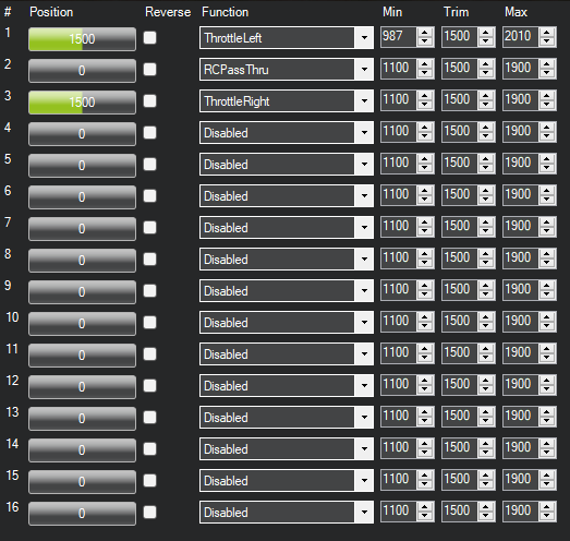
Here is the screen shot of my servo output page.
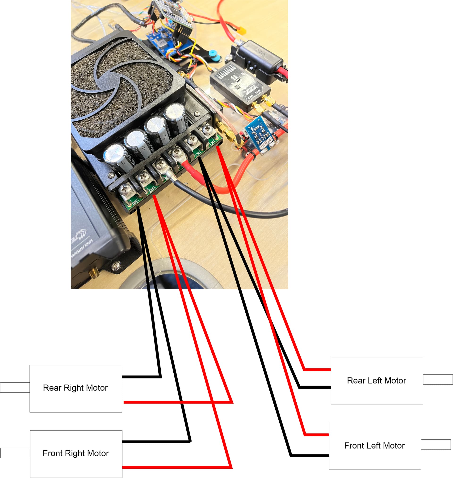
I am using an Ampflow 160 amp speed controller. Manual can be downloaded from this page if required.
I have wired it with servo 1 plug (labelled on the controller) to servo pin 1 on the FC and the second plug from the controller goes to servo pin 3 on the FC.
I’m more concerned that it appears you have output on all four wheels when the motor test is run.
Are you sure you have the controller set up correctly? It has two modes:
Two mixing options are available. Each joystick can operate one channel independently, or a single joystick can operate both channels for tank-like steering.
You should be using the independent mode, not the “single joystick” mode, which is described poorly in the paragraph from the manufacturer.
Probably unrelated, but what is channel 2 doing with passthrough?
How did you have it set up before? Having anecdotal evidence that it once worked doesn’t really solve much. It would be better to answer the question I asked.
In mixing mode (single joystick), you would set ArduPilot to output GroundSteering and Throttle. In my opinion, that is the wrong way to set up a skid steered vehicle with ArduPilot, but it’s possible that’s what was done before.
I did not have to setup the speed controller before. It worked out the box.
All I have changed on the speed controller was the RC Deadband as it was jittering slightly standing still.
I don’t know what mode came as standard unfortunately.
The default is the one that you shouldn’t be using. If you just want it to work (mostly), set your outputs to GroundSteering (26), and Throttle (70). But that will likely result in shitty turn performance and will likely preclude pure pivot turning.
Do you have a copy of the parameters from the old autopilot?
The motor controller manual describes how to change mixing modes. You need a USB to serial adapter.
RC2 is a very strange choice for LED control. That’s usually tied to pitch from a transmitter joystick, and your RCMAP parameters bear that out. You can use SERVO2 all day long, but using it with RCPassThru (on the pitch channel) is an odd and possibly problematic choice.
I do have a copy of the parameters from the Orange Cube that was previously working.
I will up load these this evening when I get home.
I have a USB serial adapter which I used to change the RC Deadband. I’ll have a look and see what the output is currently set to. Hopefully there is a way to interrogate the current settings.
I will change the RC2 for the lights to channel 5 which is unused.
I have been looking at the manual and found this on page 32.
“Factory default configuration supports traditional differential drive remote control robot operation (Combat robots, for example). The default configuration enables channel mixing so the LEFT input controls overall speed and the RIGHT input controls steering.”
Ok, let’s be clear: the motor controller you have is designed for skid steering…full stop.
Channel mixing mode (the default) is a shortcut of sorts. It is meant for those who are stuck with a signal chain that is only capable of providing a throttle signal and a steering signal. While ArduPilot can indeed output those signals, that IS NOT how an ArduPilot skid steered vehicle is intended to be set up.
The other mode (referred to as “tank” in the manual) does no mixing inside the speed controller and instead takes independent left and right throttle inputs (as you have SERVO1 and SERVO3 configured). This is the proper mode for use with ArduPilot.
Stated another way, do not let the motor controller do any mixing. Let ArduPilot handle that.
On page 5, I think the manual is somewhat clearer:
ChannelMixing(x)
Channel mixing is a global value not associated with R/C input channels or PWM output channels. The “channel” value is ignored. The value can be either 0 (Tank) or 1 (Mixed). Mixing uses the Left channel as throttle and mixes in the Right channel as steering. This is commonly used to implement single stick control for steering & throttle in remote control robots. @0sx0 – Disable Mixing @0sx1 – Enable Mixing
It looks to me like you should use the serial adapter to send @0sx0 to disable mixing followed by @0sw to save to EEPROM.
Lastly, if Mission Planner’s motor test C or D ever results in motion on all 4 wheels, something is misconfigured. You seemed concerned by differing speeds on each side, but that’s not the issue. You have a bigger problem that I think will be solved with proper motor controller setup.
Absolutely. I have not changed anything at all. It has happened three times now and each time the problem gets worse.
It is really appreciated you helping me out.
I have a clever software friend helping me out tomorrow with looking at the speed controller. Software is not my strong point as you may have gathered. I am am a mechanical engineer by trade!
Will let you know how we get on.
Well, reading that stupid manual again, I see that the controller may have a “basic PWM” input as well, meaning that ArduPilot’s brushed motor output might work. I’m guessing you wired things differently this time, rendering the basic PWM scheme moot. A picture of the connections to the motor controller might prove helpful (the manual has none, and the product page picture sucks).
Regardless, the path we are on is the correct one. The “basic PWM” control feature isn’t really the way to go with ArduPilot. Stick with RC output, change the motor controller’s mode to eliminate mixing, and things will probably work quite well.