I would be happy enough if somone donated an old clone pixhawk I wouldn’t want to take funding from future development.
FWIW, this is pretty reasonable testing. A comparison of another H7 autopilot against one that seems to struggle in long term use is valuable information.
I have been seriously considering replacing the hoverboard controllers after this recent failure. The issue is that im struggling to find replacements, the modern boards use different non stm controllers that are a pain to flash, and i cant find any old ones online, and the spare one i did have is not behaving properly.
Unfortunately it doesnt leave many options for a low cost replacement but this SIMPLEFOC controller looks interesting. It can do 2 motors at 12A for under £20 and it runs off a ESP32 so its fully programmable. I should be able to make it connect directly with mavlink.
I have ordered 3, so they should be here in a couple of weeks.
https://www.aliexpress.com/item/1005005481298844.html?
I reflashed my matek board with a STM32 programmer and it came back on like it usually does. Somone mentioned that it only happens to the early revisions of their Matek h743 board so its probably a manufacturing or design defect on my boards. so thats about £400 and a year I have wasted on 5 Defective matek boards…
Here is the process :
So basically ask for an FCU or whatever you may need like a new ESC to continue your exploration on solar rover. You need to provide the approximate cost and if possible some links.
When it is down the funding commitee will look at it and give the approval or not. We can even have some partners to step in and provide hardware.
@Yuri_Rage funding isn’t reserved for dev. It is just we rarely got non-dev proposal
I have made a first draft of a Mavlink ESP32 SimpleFOC Dual motor controller. it takes mavlink telemetry servo outputs and converts them to velocity requests, telemetry is then sent back using some named floats. Motor control runs on Core 0, telemetry runs on Core 1.
its untested as I don’t have the hardware yet.
Something that the SimpleFOC controllers have is per motor real time phase voltage and current monitoring, so it should be possible to monitor the torque and RPM output of each wheel. With that it should be possible to make a traction control system that limits wheel slip.
In theory, it could also be possible to use the front wheels as a type of bumper by detecting current spikes. When the front wheel contacts something, the torque for that the front wheel needs will go up as it will try and lift the rover over the obstruction. the rover can then stop so it doesn’t run it over and mark where that wheel is as a proximity obstruction. Essentially using the front wheels to “feel” It’s way around.
I had issues with the ESP32 sleep timer, it would immediately wake if set for more than 30 minutes, basically it works in microseconds so a regular INT overflows if you try and set more than 30 minutes, but now its been changed to a long, it can stay asleep for up to 12 hours now. I Don’t think I can get the power consumption any lower than that.
Since the SimpleFOC motor controllers are also running ESP32 chips so I have been looking into power management for them to see if it is possible to make a fast sleep mode where it will go to sleep as soon as it stops then wakes up again when it needs to start moving, it should work as long as its starts up in under 2 seconds. This could drop its consumption down to under 1mw and would be orders of magnitude better than the hoverboard controllers that use 40W at idle and 10 seconds to power them off and on.
I have been on the look for a cheap flight controller to replace the series of defective Matek H743 boards I have been struggling for over a year with at this point and due to circumstances i have had to prioritise other things so i havent been able to fund a very expensive flight controller upgrade to one of the higher end H743 boards. so I have been looking for alternatives. I checked out a lot of the DIY linux boards but most of them are EOL due to sensors that are not made anymore, I looked at esp32 but its still experimental but then I remembered about the BeagleBone Blue and Yuris efforts to simplify the install process HERE
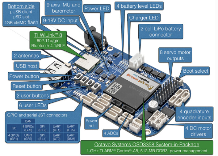
After some checking I realised it can still run the latest firmware and lua. I started looking to see if i could get one. Yuri offered me his but I can find them in the UK new for £18!! for that price its worth some effort to get it working.
I managed to get another hoverboard ESC working. There was a hall connector pin that got bent and wasn’t making contact so all 6 wheels are turning again. since they are working, im going to leave the hoverboard ESCs in and use them for a while until I figure out the simpleFOC controllers
I have been thinking that the idea of monitoring torque for anomalies could be adapted for boat use, propellers should use a very predicable amount of power at a specific RPM, so it should be possible to detect anomalies like something contacting the propeller or fouling building up over time or cavitation. if there was an anomaly then it could immediately stop the propeller for a set amount of time based on the boats speed so it can drift over it before it tries to restart, then it could then run some checks by rotating it very slowly to test for any resistance before restarting, if resistance is felt then it could do some anti-foul actions like reverse the propeller a few turns to try and unhook whatever caught on it.
I have designed some low friction 3d printed tyres for testing traction control on the new ESCs, printed in PLA they are very smooth. The problem is the tyres it has now are just too grippy with their chunky tread to test without resorting to extreme setups. These should let it slip much easier. I also wanted something that was a little kinder to the grass in the garden, the tread was ripping up chunks of grass when it tried to turn on the spot. They could also make good regular tyres if they are printed in a soft material.
My servo gimbal that has the Raspberry pi zero 2 running drone engage has been getting a lot of upgrades, Im replacing the sail winch servo I’m using to pan the camera gimbal, I thought the servo would be a good idea as it can travel 540 degrees but after testing it, it can do that range, but it has zero accuracy (±10 degrees), its very slow and just totally unsuitable for cameras. so plan b is a cheap stepper motor.
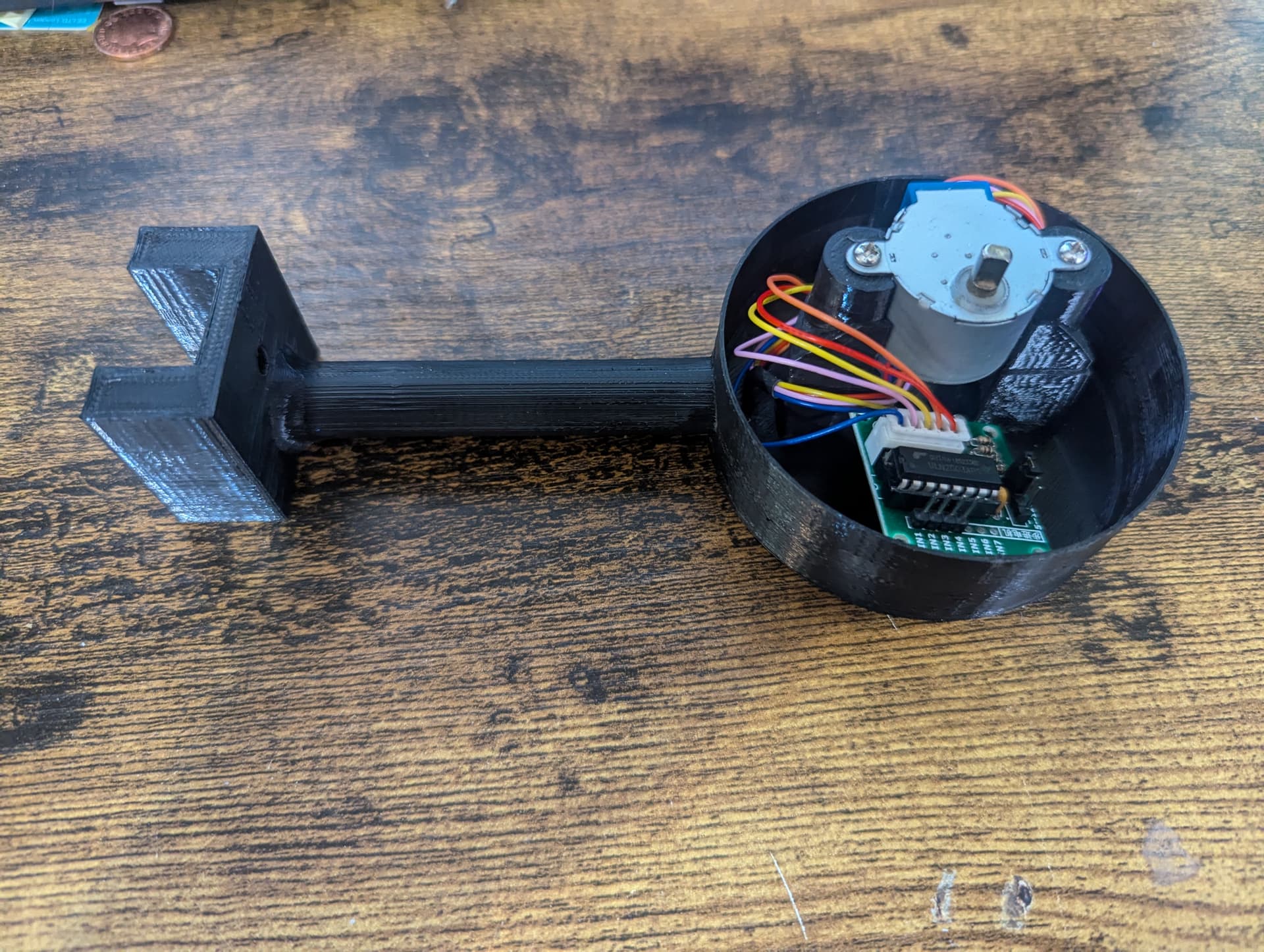
I have designed a version of the gimbal that takes a 28BYJ-48 geared stepper motor rather than a servo I still need to figure out a way if setting the starting position like a switch or remembering where it was when it went to sleep.
I have uploaded my ESP32 rover controller code here.
and the final version of the hoverboard adapter with automatic power control is here
I’m getting it ready to go out again with its improved power management, and hopefully working camera and lidar if it all checks out and is still ok after a few days I am going to try and get it to the park for a couple of days to do laps so I can get some proper power data now that it’s got accurate power sensors.
Deliveries today!.
The new Flight controller arrived, it’s chonky I have never seen a flight controller this big, it’s about the size of a PI4. what is slightly annoying is that it doesnt come with any wires at all. so i will need to order some JST1.0 connectors.
Getting it set up was a piece of cake, it took me 30 minutes from opening the box to connecting to mission planner. thanks to @Yuri_Rage and his updated setup guide.
It dwarfs my omnibus controller.
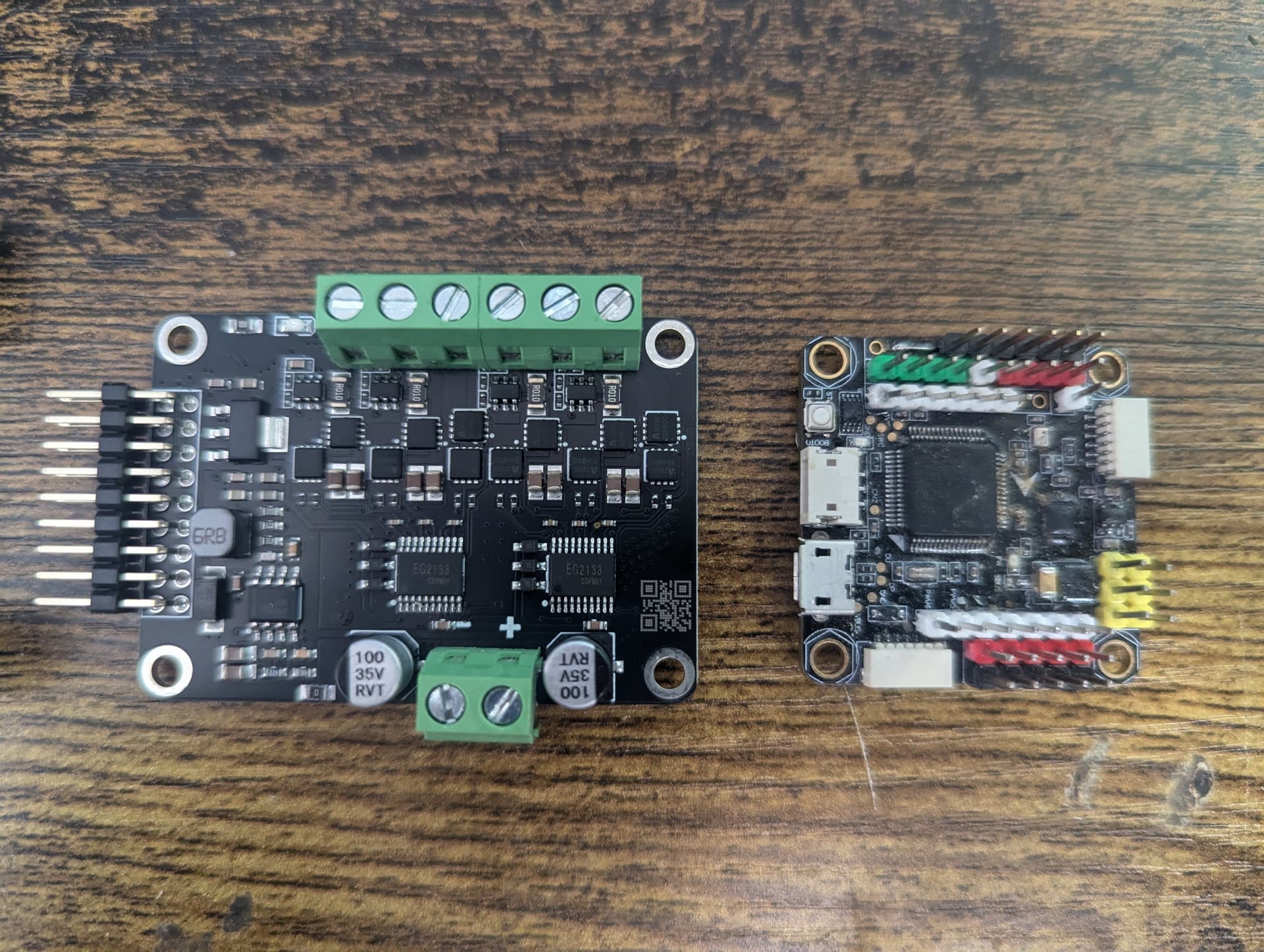
New escs arrived it’s a dual channel 12A ESP32 SimpleFOC controller. it’s tiny, about 1/4 the size of the hoverboard esc.
so the beaglebone blue is almost fully operational, running the latest ardupilot the only issue left is with the canbus GPS but I have just wired it in using serial and disconnected the RC telemetry for now.
I have updated the hoverboard controller code to fix its idle issues, basically I was mapping 1000-2000 directly to -100rpm to +100rpm, this worked fine when driving but the problem was I didn’t take into account any deadzone, so when it was stationary, if it wasn’t exactly on 1500 it would always want to move slightly. by adding a 20us deadzone it fixed that problem.
I have the SimpleFOC controllers working good enough that I’m going to install them, but since my solar rover is back outside, I’m going to install them onto my smaller urban rover for testing.
After some more digging I found that the simple FOC controllers I bought don’t have phase power measuring only total power, that’s not ideal, but I can still use it. The other issue I was having was getting the hall sensors to work. No matter what order I put them in, it was acting weird. I suspect the issue is trying to run the hall sensors on 3.3v, so I will probably need a logic level converter to get them to work. For now i have just been using the motors in sensorless mode and for what im going to be doing it’s probably going to be good enough. It just means if you overload them, then they will slip and take a second to restart rather than push all the way back to the original position.
The main thing I have been testing is the power consumption and the controllers way more efficient compared to the v1 hoverboard controllers especially at idle. It can hold all the wheels with only a couple of watts compared to the 20+ on the hoverboard controllers. with the ability to control the phase voltage in real time I’m going to make a basic algorithm that will boost torque in specific situations like turning on the spot then dropping down on low load for efficient driving. since its a esp32 it can also go into deep sleep when idle consuming only around 1mw.
I am still having issues with the LD06 lidar, I can find examples of it working in sunlight, but I get a lot of random interference when I try to use it outdoors, im currently working on some filtering that can compare every second scan to determine if there are any false readings.
void MAP_MAVLINK() {
if (send = 0) {
if (ld06.readScan()) {
uint16_t n = ld06.getNbPointsInScan();
for (uint16_t i = 0; i < n; i++) {
lidarAngle = ld06.getPoints(i)->angle;
distances0[lidarAngle] = (ld06.getPoints(i)->distance / 10);
}
send = 1;
}
}
if (send = 1) {
if (ld06.readScan()) {
uint16_t n = ld06.getNbPointsInScan();
for (uint16_t i = 0; i < n; i++) {
lidarAngle = ld06.getPoints(i)->angle;
distances1[lidarAngle] = (ld06.getPoints(i)->distance / 10);
if (distances1[i] > (distances0[i] - 20) && distances1[i] < (distances1[i] + 20)) {
messageAngle = map(lidarAngle, 0, 360, 0, 72);
if (distances1[lidarAngle] < messageAngle && distances1[lidarAngle] > 5) {
distances[messageAngle] = (ld06.getPoints(i)->distance / 10);
}
}
}
send = 0;
I have a new BMS library to test to get my bluetooth BMS to communicate with ardupilot, This library looks much more promising as it’s their app that I use on my phone for them. I still need to get ardupilot to use the mavlink battery data using this script.
local mavlink_msgs = require("mavlink/mavlink_msgs")
local msg_map = {}
local battery_status_msgid = mavlink_msgs.get_msgid("BATTERY_STATUS")
msg_map[battery_status_msgid] = "BATTERY_STATUS"
-- initialise mavlink rx with number of messages, and buffer depth
mavlink.init(1, 10)
-- register message id to receive
mavlink.register_rx_msgid(battery_status_msgid)
function update()
local telem_data = ESCTelemetryData()
local msg,_,timestamp_ms = mavlink.receive_chan()
if msg then
local parsed_msg = mavlink_msgs.decode(msg, msg_map)
if(parsed_msg.msgid ~= nil and parsed_msg.msgid == battery_status_msgid) then
telem_data:voltage((parsed_msg.voltages[0] or parsed_msg.voltages[1]) / 100)
telem_data:temperature_cdeg(parsed_msg.temperature)
telem_data:current(parsed_msg.current_consumed / 1000)
esc_telem:update_telem_data(1, telem_data, 0x0D)
end
end
return update, 1000
end
return update, 1000
void MAVLINK_BATTHB() {
uint8_t autopilot_type = MAV_AUTOPILOT_INVALID;
uint8_t system_mode = MAV_MODE_PREFLIGHT; ///< Booting up
uint32_t custom_mode = 0; ///< Custom mode, can be defined by user/adopter
uint8_t system_state = MAV_STATE_STANDBY; ///< System ready for flight
mavlink_message_t msg;
uint8_t buf[MAVLINK_MAX_PACKET_LEN];
int type = MAV_TYPE_GROUND_ROVER;
// Pack the message
mavlink_msg_heartbeat_pack(1, 180, &msg, type, autopilot_type, system_mode, custom_mode, system_state);
uint16_t len = mavlink_msg_to_send_buffer(buf, &msg);
Serial1.write(buf, len);
}
void MAVBATTERY() {
uint16_t CELLSA[10] = { CELLS[0], CELLS[1], CELLS[2], CELLS[3], CELLS[4], CELLS[5], CELLS[6], CELLS[7], CELLS[8], CELLS[9] };
uint16_t CELLSB[4] = { CELLS[10], CELLS[11], CELLS[12], CELLS[13] };
uint8_t system_id = 1; // id of computer which is sending the command (ground control software has id of 255)
uint8_t component_id = 180;
mavlink_message_t msg;
uint8_t id = 0;
uint8_t battery_function = 2; //propulsioni
uint8_t type = 3; //liion
int16_t temperature = bms.get_ntc_temperature(1);
uint16_t* voltages = CELLSA;
int16_t current_battery = CURRENT;
int32_t current_consumed = (20000 - CAPACITY);
int32_t energy_consumed = 10000;
int8_t battery_remaining = SOC;
int32_t time_remaining = (CAPACITY / CURRENT);
uint8_t charge_state = 1;
uint16_t* voltages_ext = CELLSB;
uint8_t mode = 0;
uint32_t fault_bitmask = 0;
//Pack battery message
uint8_t buf[MAVLINK_MAX_PACKET_LEN];
mavlink_msg_battery_status_pack(system_id, component_id, &msg, id, battery_function, type, temperature, voltages, current_battery, current_consumed, energy_consumed, battery_remaining, time_remaining, charge_state, voltages_ext, mode, fault_bitmask);
uint16_t len = mavlink_msg_to_send_buffer(buf, &msg); // Send the message (.write sends as bytes)
//if (CELLS[1] > 1) {
Serial1.write(buf, len); //Write data to serial port
//}
}
progress!
https://www.aliexpress.com/item/1005006347440227.html
its been outside for around 2 weeks and its now lost contact over drone engage again so I brought it in and I cant connect over udp or usb serial with mission planner. tried the latest beta, and an old laptop that had not been updated.
Q ground control seems to connect and work connected to the flight controller UDP but over USB serial its doing the same thing as before where it sends data but wont respond.
I have downgraded ardupilot to the latest stable from the latest beta and it didnt change anything.
since this is a linux controller and ardupilot is just files on an operating system it makes it much simpler to find out where the problem is, i started out by looking for all the files i could find related to ardupilot then renaming them one at a time until it eventually started up again.
I found a file called /var/lib/ardupilot/Rover.stg and when i deleted it the flight controller came back but with all the settings missing. I think its the linux equivalent to the eeprom.
I have the faulty file if somone wants to have a look at it.
RoverB.zip (1.3 KB)
After some more research I think I’m running into 2 different flash corruption issues.
One is h743 flash corruption due to brownout on startup.
One is beaglebone blue emmc corruption from switching it off without shutting it down first.
So to fix the beaglebone issue it should be as simple as adding a wire to the shutdown button so it can be shutdown before power is removed.
in order to try and stop the beaglebone from corrupting when power is cut to it, I have wired in its power button to a relay that I can control. then I’m using a pin on the esp32 to monitor the 1.8v power rail on the beaglebone so it doesn’t try and switch unless its in the correct state.
The BMS was installed, I had it connected to the motor controller but I realised I would need to power it up in order to read the BMS so I just rewired it directly to the esp32 so it can read it in its lowest power modes. it was looking good until it overcharged the battery, I didnt realise that the ground on the serial connector was directly connected to the battery so when it was fully charged and the BMS cut off the power just rerouted via the serial ground wire and kept charging.
So to get around the problem im looking at connecting to it via the BMS native BLE bluetooth interface using the main esp32 controller, I have some code working on its own but trying to integrate it has been a nightmare, basically using BLE uses a LOT of memroy on the esp32, so I have had to move up to a 16mb esp32 for it to fit.
I have RTK RTCM injection working on the esp32 controller, it connects to rtk2go for the RTCM stream then converts it to mavlink before exits sent to the flight controller via the mavlink telemetry link.
I have installed a 868mhz Halow WiFi adapter into the rover , since I’m just going to be testing close to the house I can use this to save spending money on LTE data. it should be good for around 1km, the way i have set it up is if the halow connection is lost it will automatically switch on the LTE modem and switch to it.
I have also recently received a pair of meshtastic radios, they aren’t fast enough for a full mavlink datalink but it should be adequate for sending high latency packets over very long distance. It should work as a backup of I loose communication I should be able to send up a drone to see over the curvature
I have been testing the power consumption and I didn’t like how much power it was using with all the relays, a single one doesn’t use much but once you have 12 switched on its a noticeable amount of power and things start heating up. To try and reduce its power consumption I have changed out the relays for one of these PLC controllers, It’s essentially just a esp32 with 4x 8 channel i2c gpio chips. I was using the same esp32 chip and gpio controller to drive my relays so it was relatively simple to get my code running on it. I have now split my code so all the power switching is now done by this board, leaving my main esp32 to handle navigation and telemetry. Its power consumption is surprisingly low, only 500mw at idle and 1.7w with all its outputs turned on.
Speaking of my main controller, I finally got it to do NMEA to mavlink conversion for the GPS and it being accepted by the flight controller as valid data, one of the main issues I was having was getting the GPS update to reliably run at 5hz with everything else it was already doing. i tried multithreading but it was still struggling, so I have upgraded it from a standard esp32 to an esp32-S3, this run much faster and it can now keep a reliable 5hz output. The downside was the s3 pin numbers are all different, so i ended up replacing the expansion board and decided to go with one with servo connectors rather than screw terminal to tidy up the wiring.
I have reconfigured the management of the LTE and HAlow connections, i have now set it up is that the 4g should always connect so it starts up and connects over LTE and if the switch is set for it to use halow it will turn it on and then if it detects it’s connected it will switch over and turn off LTE. if connection is lost it will switch back to LTE. The first time i tested this didn’t go so well, and I ended up having to hotwire some relays to turn it on so i could drive it back from the park.
I have changed out the flight controller to my old clone pixhawk, it doesnt have any corruption issues so it simplifies a lot of things, I have been able to simply the power system a lot since I changed back to the pixhawk, It originally had a 5v UPS for the main esp32 controller and modem then a 12v UPS for the flight controller to try and stop it corrupting but now that controller has been removed I no longer need a 12v UPS in the rover, the only things that will have backup power will be the main ESP32 and LTE modem on 5v.
That looks really great. Can you please provide a link to the PLC controller board? It looks like it could be a very handy thing.
Thanks, Grant.
Its a KC868-A16, I got it off ali express for £20, im also looking to use it for a universal lawnmower interface. It can be connected with a mavlink serial port or ethernet then it can get raw servo data over mavlink so my idea was to plug a PCA9685 servo controller into its i2c port then map channels 1-16 to the servo output and 17-32 controlling the switch outputs on the board. by enabling 32ch output on the flight controller, its sent in 2 16 channel ports, so
port(0) 1-16 = 1-16
port(1 )1-16 = 17-32.
I wasn’t thrilled about using a clone pixhawk on my rover, they are reliable enough but I was concerned about its power system and its lack of protection that could possibly result in corruption so i have replaced it with a pixhawk 2 black cube that i found online for £65 and to power it i bought a cube mini power module, my hope is that this should fix all my corruption problems and be more reliable than a clone pixhawk.
To switch my halow wifi adapter and the mini 2.4ghz router attached to it I was using 2 relays at first, this is because the halow adapter uses 12v and the 2.4ghz router uses 5v, so to simplify it i have installed a DPDT Relay module that will switch them both together. im still working on the logic to switch between halow and LTE,
I am still working on simplifying the interface with the flight controller, so rather than plugging my NMEA AIS/GPS receiver into the flight controller i have added mavlink adapter code to my esp32s3 controller that takes the NMEA and then sorts the messages into AIS and GPS, that is then converted to Mavlink GPS and AIS messages that are then sent to the flight controller with the rest of the mavlink data rather than needing its own serial port on the flight controller, it also gets around the problem that there is no unified NMEA interface on the flight controller so there was no way to use the NMEA AIS and GPS without wiring the receiver into separate ports that are set for GPS and AIS.
I have finally got a replacement RTK GPS, the Here+ that I have been using is useless as the M8P receiver cant hold a stable fix. im going to keep it on as the compasses are decent.
This is the DATAGNSS NANO Dual-Antenna RTK Receiver, Their website is rather deceptive, On the main page it says that its compatible with ardupilot,
its not until you get you the very bottom of the product wiki that it says in very light font that its only compatible if you make a custom firmware.
so Unfortunately it turns out to get yaw from it, you have to parse the custom nmea message and that isn’t supported by ardupilot, so I have added a second GPS++ instance with custom fields on my esp32 that will take the nmea messages, parse them and convert it to a mavlink GPS with heading to get around that problem, The ESP32 also connects to rtk2go over LTE and sends corrections directly to the GPS without needing the flight controller to do anything. turns out this is much simpler than trying to convert RTCM into mavlink so its sent through the flight controller.
I was having a lot of problems with the LD06 lidar when the sunlight hit the sensor it would generate a lot of false objects and cause it to just go in circles trying to find a way past the non-existent obstruction, turning up the confidence filter and adding some sorting got rid of most of the interference but it was still there. Recently I read a post about someone testing the LD19 lidar and having a lot better results outdoors, so I have ordered one to test, hopefully that fixes my lidar issues .
Great update! Thanks - am curious how you end up using lidar…
I have been repackaging all my sensors, the mast was starting to look like a christmas tree with everything hanging off it. So my first effort has been to combine the lidar, LTE modem, and the gimbal with a pizero and cameras into one unit, so i started with this
and this mount for the lidar
so to modify it first I expanded the arm so the USB LTE modem can fit inside,for that to fit I had to make the gimbal taller in order for the lip of the top cover to clear the arm. The plan is to install the lidar on the underside of the gimbal. in an attempt to stop water running down onto the lidar, I added a small skirt so the water has to run off and cant run down onto the lidar.
I have also added a cover to the lidar that will stop any water ingress to the ld19.
I have started printing everything with clear plastic, its much easier to diagnose everything if you can see what lights are on.
I have 8x RGB leds arouond the gimbal that illuminate and change colour based on the 8 proximity faces, so at max range the led is blue then it changes through green and eventually to red. this makes diagnosing rangefinder issues much easier
I have changed the cameras around, the original plan of using a single pi camera didnt work as most of them are terrible in low light,
I recycled some cameras I wasn’t using, on the left with the long lens is the pi camera, in the centre is a runcam night eagle 3 from one of my old planes and on the right is a flytron drone thermal camera.
The thermal camera is about 10 years old I bought it a few years ago off ebay because it was going very cheap but I have never actually had a use for it. I was going to use my 256x192 usb thermal camera on the rover but i end up using it quite often for diagnosing electronics and i didnt want to buy another one so i changed it out for this flytron 80x80 resolution lepton core camera that was gathering dust.
its very low quality video, you can get far better for a fraction of the price these days
to connect them i used a a USB video capture module connected to the Pizero2
and a 3 channel analogue video switcher to select what camera i can see.
I have also done my GPS mounts transparent to make the lights stand ut more
The Gps antennas for the RTK receivers have been installed at either side of the solar panels.
Love the clear filament idea. Am rejiggering my v2.0 control boxes as well…
I ended up redesigning everything again,
I was using espeasy firmware on a esp32 for my weather sensors, but i have just wrote a program to do it myself, it gives me some more flexibility.
Rather than mounting the lidar under the cameras I have moved it to its own mount that can sit lower down, I have extended it to give a smaller dead zone behind the mast.
in its place I have mounted the AI camera and its radar, Rather than mounting the Radar above the camera I have made a bracket that lets the radar be mounted on top of the camera just under the lens
I have made proper brackets for lots of small parts that were just taped on before
Box for weather sensors and GPS antenna
DHT22 humidity
the omni radar
Rain sensor
I remade the camera gimbal so there was more space for future expansion, i have also removed the 3 channel switcher and just gave each camera its own usb-av adapter. the pi camera has also been removed and replaced with a HD usb camera module.
I have replaced the little indoor security camera with a cheap tapo C500 outdoor camera, the main reason for this camera is that it has an intercom so I can talk to people.
The best news so far is that i have finally got arduino talking to my Ollama LLM server, I want to eventually send it photos for path planning.
I have been experimenting with different vision llms to see what was the smallest model to give a reasonable answer. I’m thinking for just asking “are there any obstructions ahead” while on the move i can use a small fast model like gemma2 4b but for if something is detected and I need more detailed analysis and navigation I can use one of the larger 12B or 27B models.
I would like it to run on a computer on the Rover but I don’t think I have the power or financial budget for that.
Other than the AI stuff, it’s basically complete now, so I want to get it outside in the next week so I can test the new RTK GPS and lidar .
What i would like to do at some point is connect the lidar to the AI camera, the problem with using the radar with the AI is that the camera has a very wide FOV so sometimes the radar cant see the object if its at the edge of the picture. I’m going to try and tie the lidar to the camera so it can’t see it on radar it can use the lidar as its got full coverage.


