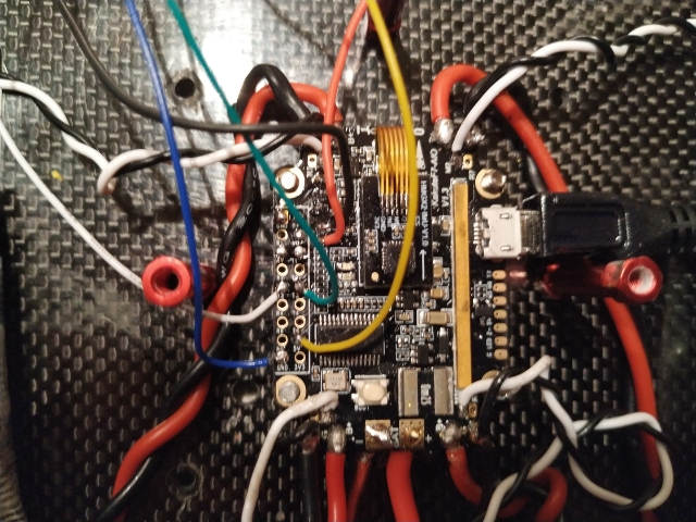
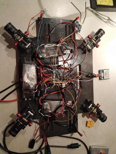
I have done quite a lot of testing with the omnibusv6 (not nano), and below are most of the details for setting it up based on my earlier pull request. I haven’t got to help out with the board description yet, but I did write it up back then. It’s quite similar to the nano but with some differences.
It is nice with the JST pins for GPS/COMPASS (per previous comment as I always get the soldering wrong). I have tested with a benewake lidar and esp8266 (wemos) for connection to ground station (so the board runs with all these plus gps/compass).
Board Connections (per March 2019 on master)
GPS (enabling use of the 6 pin JST for GPS/COMPASS)
SERIAL3_PROTOCOL # USART6
COMPASS (scl/sda at the default 6 pin JST)
Telemetry
SERIAL2_PROTOCOL # USART4
Available UART (lidar, GSC etc)
SERIAL4_PROTOCOL # USART3
RC input to be soldered to LED PIN (compatible with RX serial protocols).
Servos S5-S6 are available for use
Current/Voltage monitoring:
-
BLHeli32:
BATT_MONITOR 9
BATT_VOLT_PIN -1
BATT_CURR_PIN -1
-
ADC battery monitor:
BATT_MONITOR 4 (Analog Voltage and Current)
BATT_VOLT_PIN 12
BATT_CURR_PIN 11
BATT_VOLT_MULT 11.0
BATT_AMP_PERVOLT 38.0
RSSI
Option 1: RSSI_TYPE 2 (RX RSSI Analog input from receivers (Frsky etc.))
RSSI_CHANNEL (set to the channel number output from the receiveer, for example 16)
Using usart3 to connect to GS
SERIAL4_PROTOCOL 2
SERIAL4_BAUDRATE 921600
Connect to wifi, select UDP and 921600 Baud and connect.
To enable logging, set LOG_BACKEND_TYPE to 4
order of UARTs
UART_ORDER OTG1 USART6 USART1 UART4 USART3
Serial ports
R1/T1 -> USART1
R6/T6 -> USART6
R3/T3 -> USART3
R4 -> UART4 (only RX)


