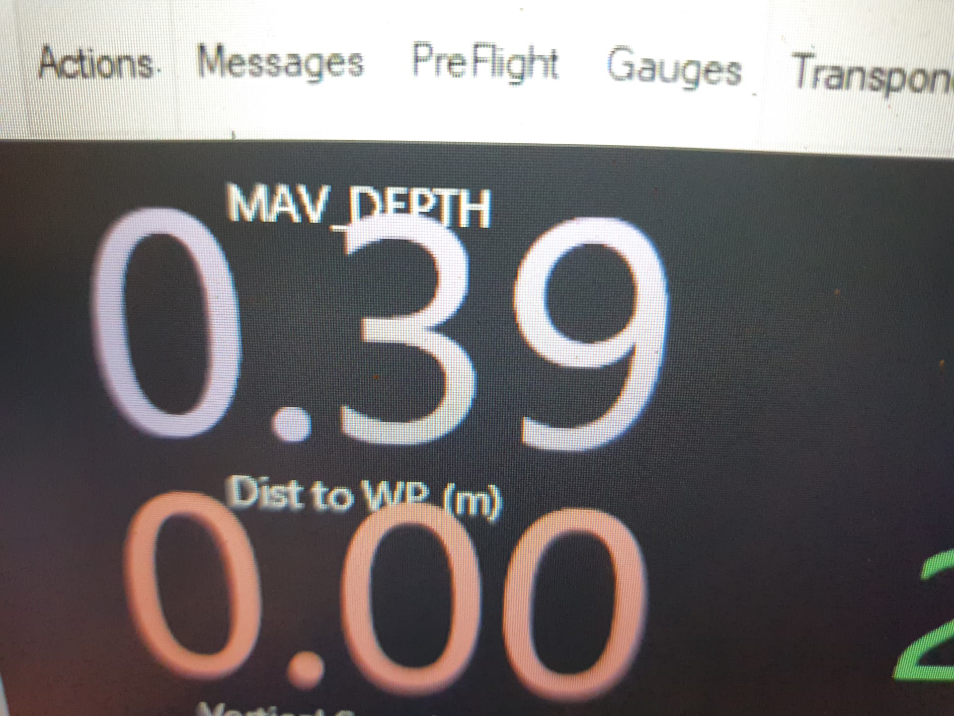
not yet, there is an open issue for it, I just monitor it from the onboard phone using the app for now.
I have a plan for getting around it, basically set it up as a standard SR04 then multiply it in lua by 4.21 to get the corrected distance then use that for alerts and actions. the corrected value can be send back through the telemetry.
I have finally got around to getting things done on the boat, mostly just been going through it all again after updating the firmware to 4.3 and setting everything up again as it was that long ago as I have forgotten most of it.
Dshot and blheli telemetry are working so I get voltage current and RPM of the main motors and they have fixed the reverse bug.
Power box is almost finished with the BMS, MPPT and balancer along with 2x ina226 power sensors in it to monitor the solar output, im having issues getting the power sensors to get recognized, the other 2 I have on the 18650 backup batteries work so I don’t know what’s going on with them, I’m going to order another 2 just in case. the plan is to eventually be able to read the BMS in ardupilot for battery monitoring.
I changed the mobile phone connection from usb back to a usb-serial adapter, I was having problems getting it to reconnect whenever the flight controller restarted as android kept seeing it as a new device.
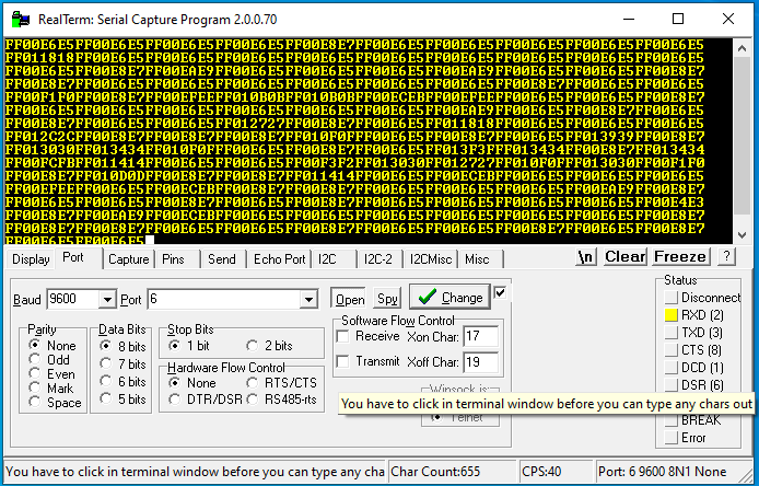
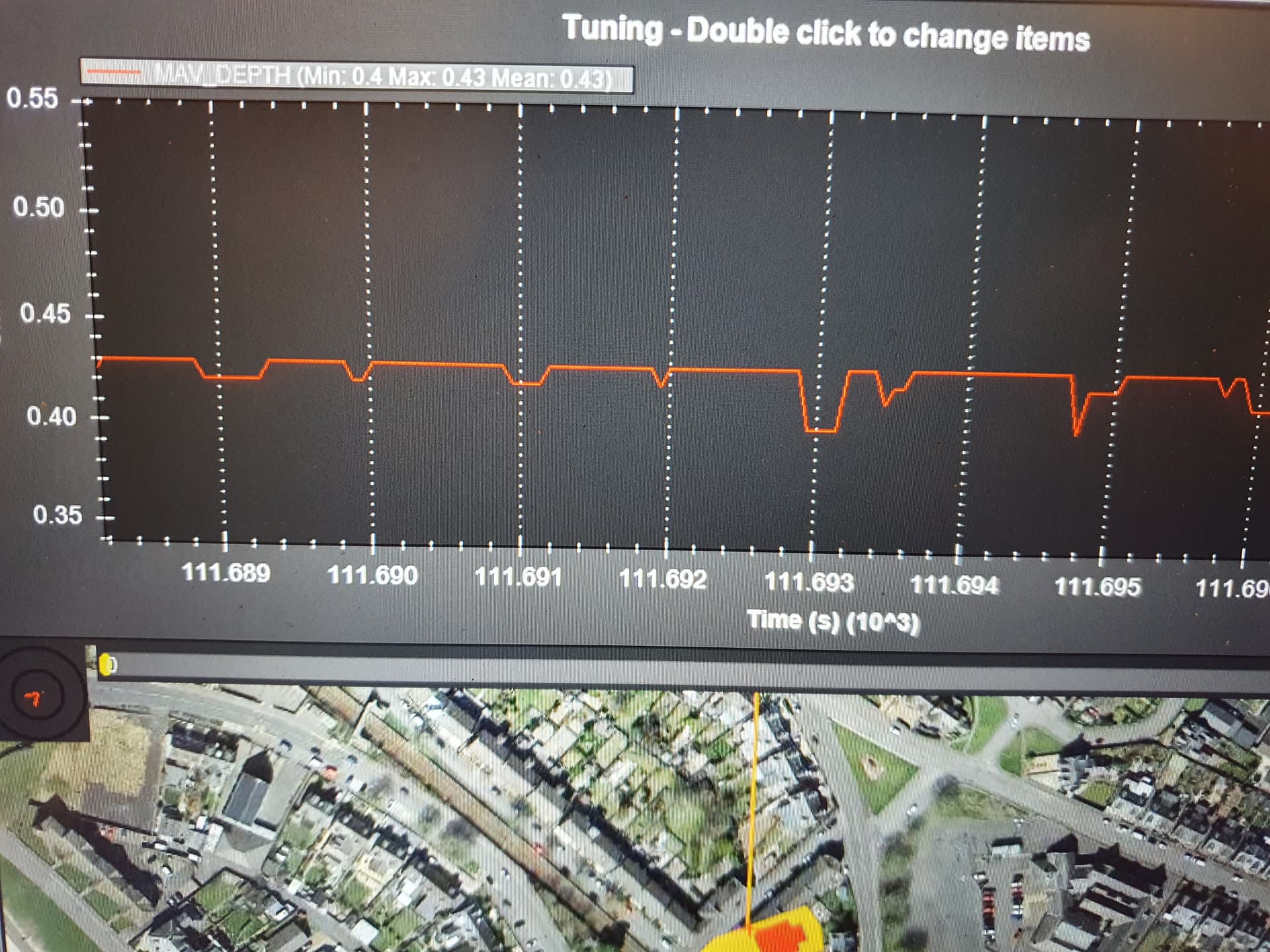
Sonar depth sounder is a work in progress, I have a test script for scaling the range of a sr04 in lua so the modified sr04 driver is not required but the ultimate goal is to get the sonar working in serial mode as it will give the fastest and most accurate measurements. the plan for that is to read the values directly from the serial port and just reading it into lua, that way we’re skipping all the ardupilot drivers and libraries, since its not getting used for proximity or altitude it shouldn’t matter.
I tried getting the tfmini plus working via the M8Q CAN GPS i2c port but it wasn’t being recognized, it works fine when connected directly to the pixhawk so i need to look into AP_periph more to figure it out.
Im running the motors and servos via a SBUS-PWM decoder to simplify the wiring so to make it tidier I installed a pwm controlled switch instead of the GPIO relay I was using before to simplify the wiring but totally forgot there is no such thing as a PWM relay on ardupilot so my auto bilge pump setup wont work so im going to have to change it back or use another script to make the pwm output match the relay status. I will probably replace the SBUS decoder with a CAN node at some point.
1 Like
With some lua scripting from @Yuri_Rage we have a test script that reads the JSN-SR20-Y1 in serial mode, hopefully i can get it tested in deeper water in the next few days.
1 Like
Turns out 2x of the ina226 power sensors that monitor the mppt charge controller were faulty, not sure if i damaged them, but i have replacements ordered and the other 2 on the backup batteries give very strange readings, 20ma when charging and 89.99A when discharging.
Bilge pump has been rewired back to a GPIO pin set as a relay output that way the auto bilge pump triggered via a button works again. since you cant get pwm output to drive relays it has to be a GPIO pin.
Wind sensor direction is working via the ADC input but im not getting anything from the hall sensor on the wind speed so i suspect it needs a pull up resistor on the hall sensor to get it working.
I will probably have to replace the pixhawk flight controller as I think im running into memory limitations. With so many features active Im getting memory errors with lua and MAVFTP stops working. I will probably go to a matek h743 at some point but its a huge rewire so if i can use the pixhawk on this boat i will.
Im working on a motor control script to manage the groups of motors. My plan is to use lua to select what groups of motors will be active based on flight mode, sail 3 position switch and battery voltage By setting the servo min and max parameters to 1500 i can disable a motor. One group will be the thrusters and the second group will be main motors, i could also disable one of the main motors to save power if the battery is really low, this is to get around this issue where arduboat will try and use motors for yaw control even when sailing.
And finally, I have all the parts to build a phased sonar array ordered. Im not 100% sure that i can make it work underwater, but it will be amazing if it does. from what I can figure out from the video and the code all I should have to do is just change the speed of sound constant to get it to work in water and use waterproof transducers. I have all the code running, I’m just waiting for the parts to start testing.
im replacing the transducers he used in the video with the waterproof ones i have been using for the depth sounder sr04 and using some motor driver modules that are easier to solder together without a custom pcb.
essentially, its a ESP32 driving transducers via some motor drivers.


")
1 Like
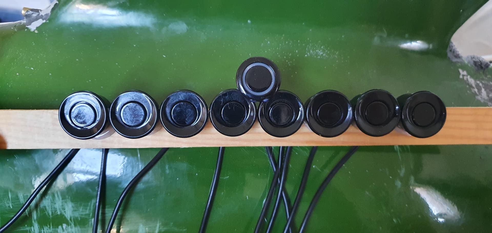
I have a total of 4 ultrasonic rangefinders under the boat now, one forward, left, right and down. Now that i can run them as i2c rangefinders and scale them it means i can use them as underwater proximity.
The forward rangefinder is at around a 45 degree angle. My idea is to test it as forward looking proximity to stop it running aground. It was an idea @rmackay9 suggested a while ago but now I can add a lot of rangefinders its an idea worth testing.
I Edited the Mavlink POC rangefinder code to work with 8x VL53l1x 4m rangefinders and then ordered 8 water proof sensors, this should give me 360 4m short range proximity around the boat for around £35
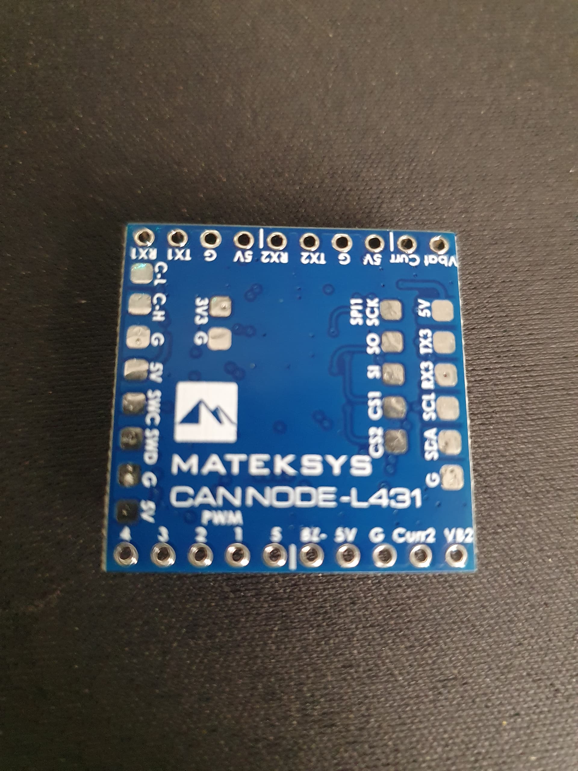
Can node arrived, thenplan is to use it to run the solar panel servos, the sail and possibly some rangefinders.
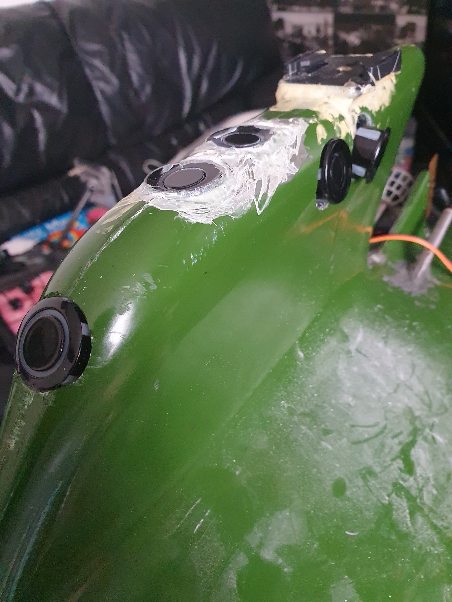
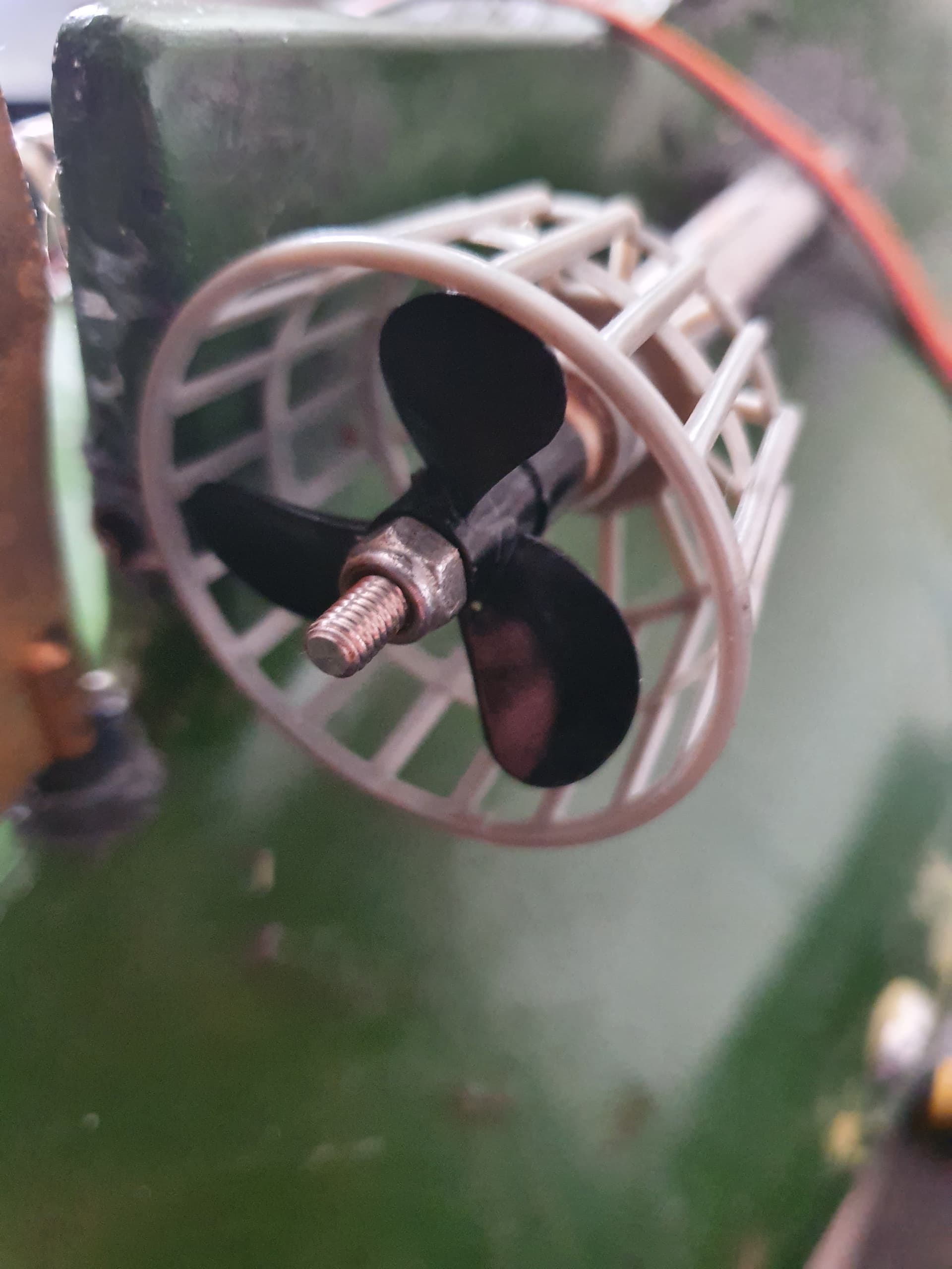
I got around to test fitting the bait boat prop guards I bought off ali express and they fit perfectly after drilling it out for the thicker prop shaft.
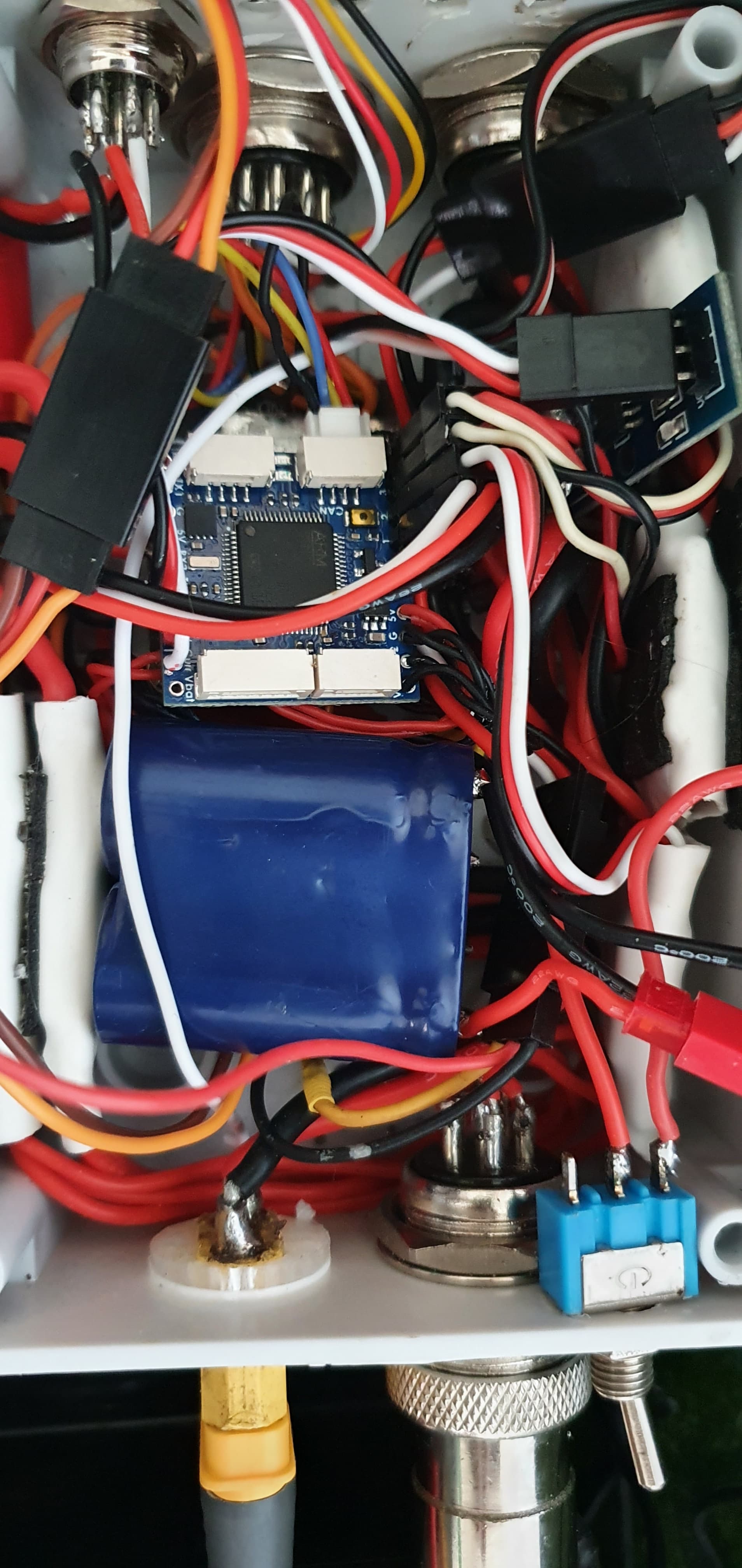
I have been slowly convertingmy boat to canbus. It started with a matek f303 canbus gps module to figure out how it worked then adding matek l431 sensor nodes replace as much of my wiring with can bus as i can.
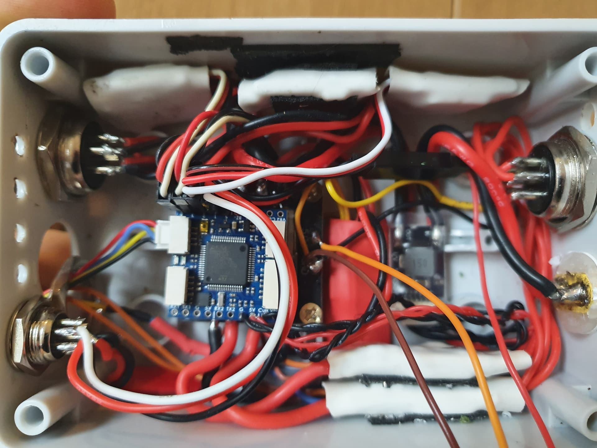
the motor control box has had its node installed but its still lacking some features to allow me to remove all the other wires joining to the pixhawk mainly sbus out and i2c support for the ina226 power sensor that monitors the servo backup battery.
The second node is set up to handle the 4 solar panel servos, rotate the mast and monitor the power from the solar panels.

1 Like
this is my test lua for motor control groups, essentially the idea is to enable and disable motors based on a switch position. it will eventually be expanded to include control rate settings and possibly automatic switching based on battery,speed or esc telemetry parameters.
local SCRIPT_NAME     = 'group motor control.lua'
local RUN_INTERVAL_MS	 = 200
local RC_OPTION   		= 300

local THROTTLE				=70
local THROTTLE_LEFT			=73
local THROTTLE_RIGHT		=74
local OFF					=135
local MOTOR_1				=33
local MOTOR_2				=34
local MOTOR_3				=35


local MAV_SEVERITY_INFO      = 6

-- wrapper for gcs:send_text()
local function gcs_msg(severity, txt)
    gcs:send_text(severity, string.format('%s: %s', SCRIPT_NAME, txt))
end

-- ! setup/initialization logic
local rc_chan = rc:find_channel_for_option(RC_OPTION)
local last_sw_pos = nil

function update()
    local sw_pos = rc_chan:get_aux_switch_pos()  -- returns 0, 1, or 2

    -- added this line to make things cleaner than YouTube demo script
    if sw_pos == last_sw_pos then return update, RUN_INTERVAL_MS end

    if sw_pos == 0 then
		param:set('SERVO1_FUNCTION', OFF)
		param:set('SERVO2_FUNCTION', OFF)
		param:set('SERVO3_FUNCTION', OFF)

		param:set('SERVO13_FUNCTION', THROTTLE)
		param:set('SERVO14_FUNCTION', THROTTLE)
	)
		gcs_msg(MAV_SEVERITY_INFO, 'Ackermann  ')

	if sw_pos == 1 then
		param:set('SERVO1_FUNCTION', OFF)
		param:set('SERVO2_FUNCTION', OFF)
		param:set('SERVO3_FUNCTION', OFF)

		param:set('SERVO13_FUNCTION', THROTTLE_LEFT)
		param:set('SERVO14_FUNCTION', THROTTLE_RIGHT)

		gcs_msg(MAV_SEVERITY_INFO, 'skid-steering')


    else

		param:set('SERVO1_FUNCTION', MOTOR_1)
		param:set('SERVO2_FUNCTION', MOTOR_2)
		param:set('SERVO3_FUNCTION', MOTOR_3)

		param:set('SERVO13_FUNCTION', OFF)
		param:set('SERVO14_FUNCTION', OFF)
		gcs_msg(MAV_SEVERITY_INFO, 'OMNI')
    end

    last_sw_pos = sw_pos

    return update, RUN_INTERVAL_MS
end

gcs_msg(MAV_SEVERITY_INFO, 'Initialized.')

return update()
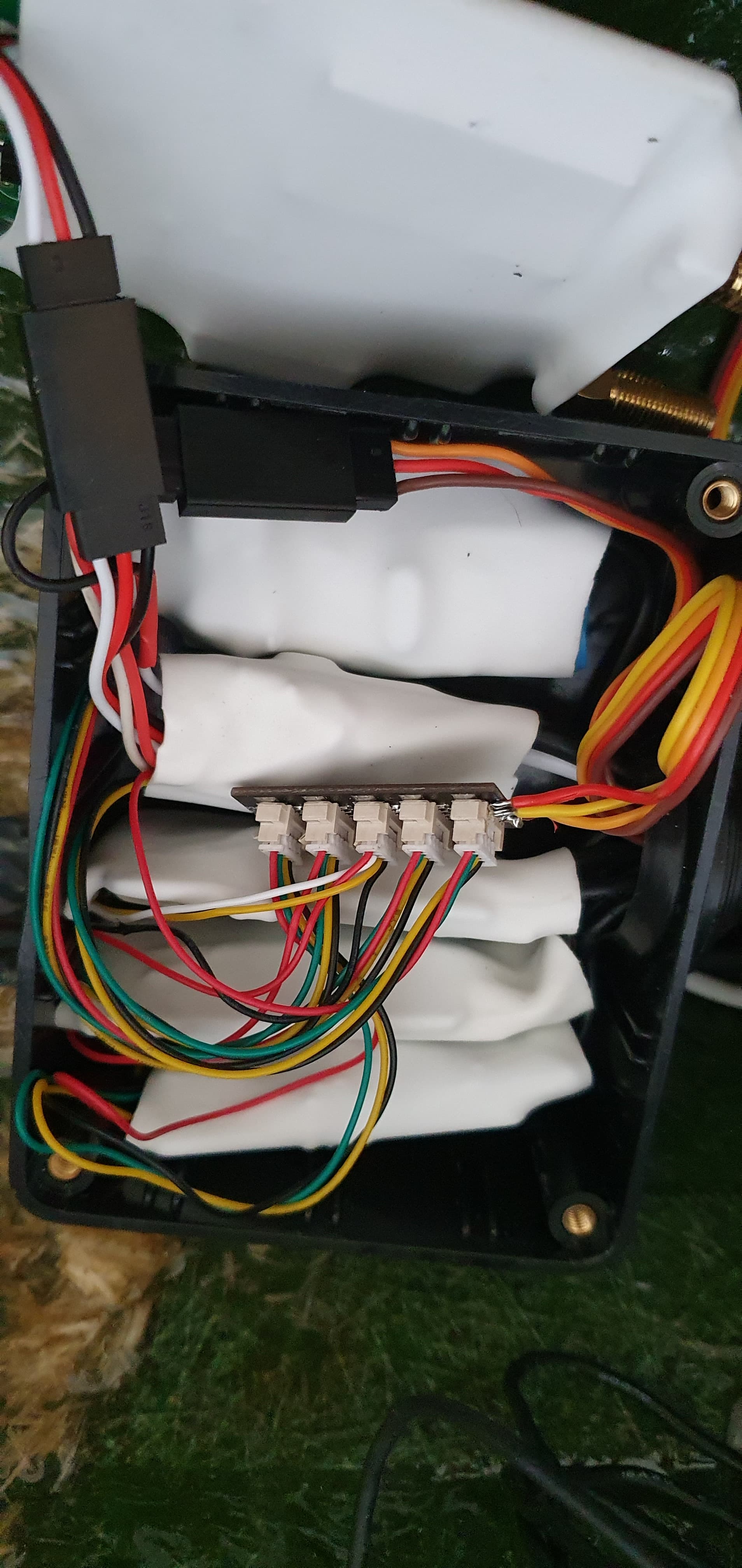
The 4 sonars are finally all wired in along with one of Yuri_Rages sensor adapter boards, the bilge water sensor and the AIS receiver.
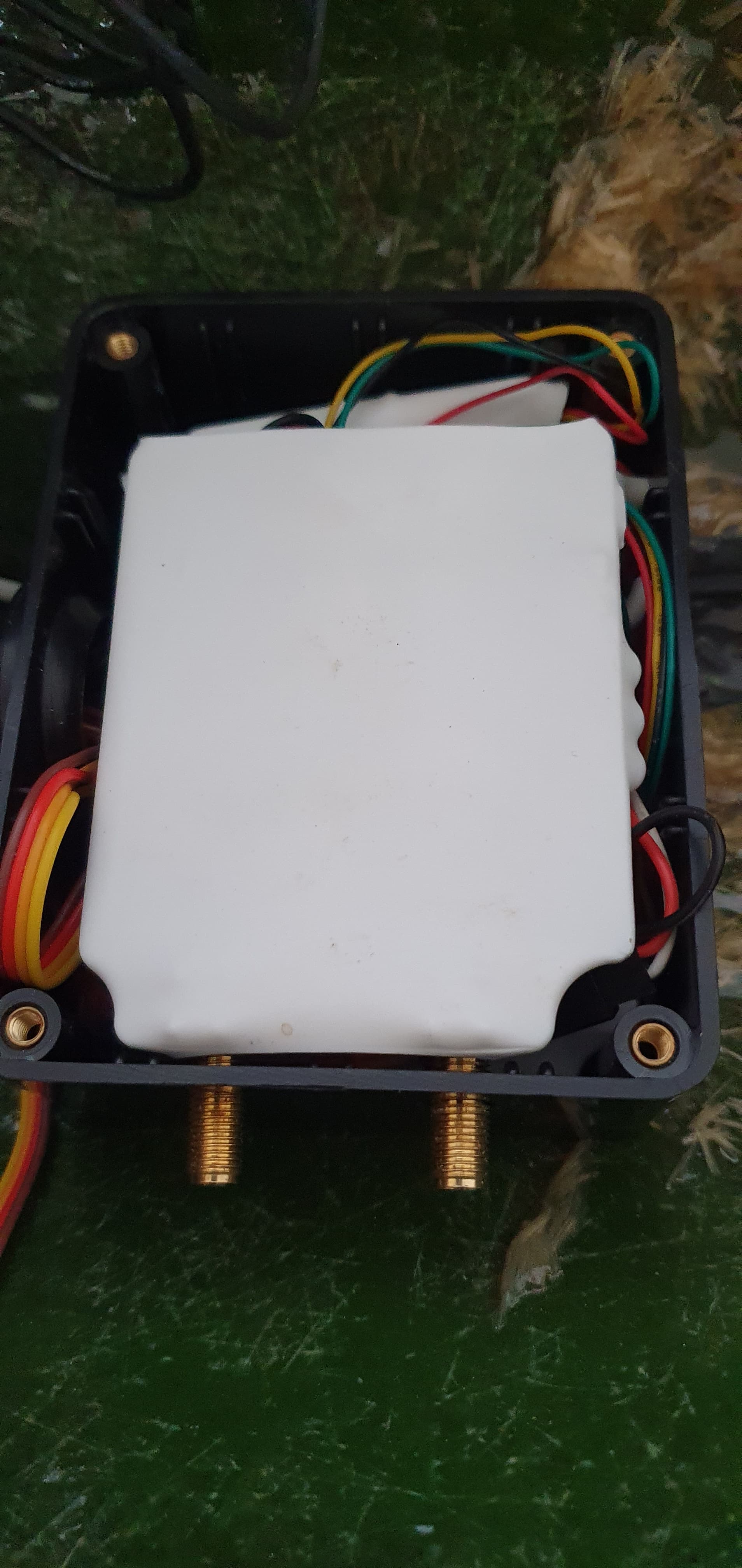
Power box is also done, it was supposed to have more sensors in it but i have moved some functionallity like the power monitoring of the solar panels to the can node on the deck.
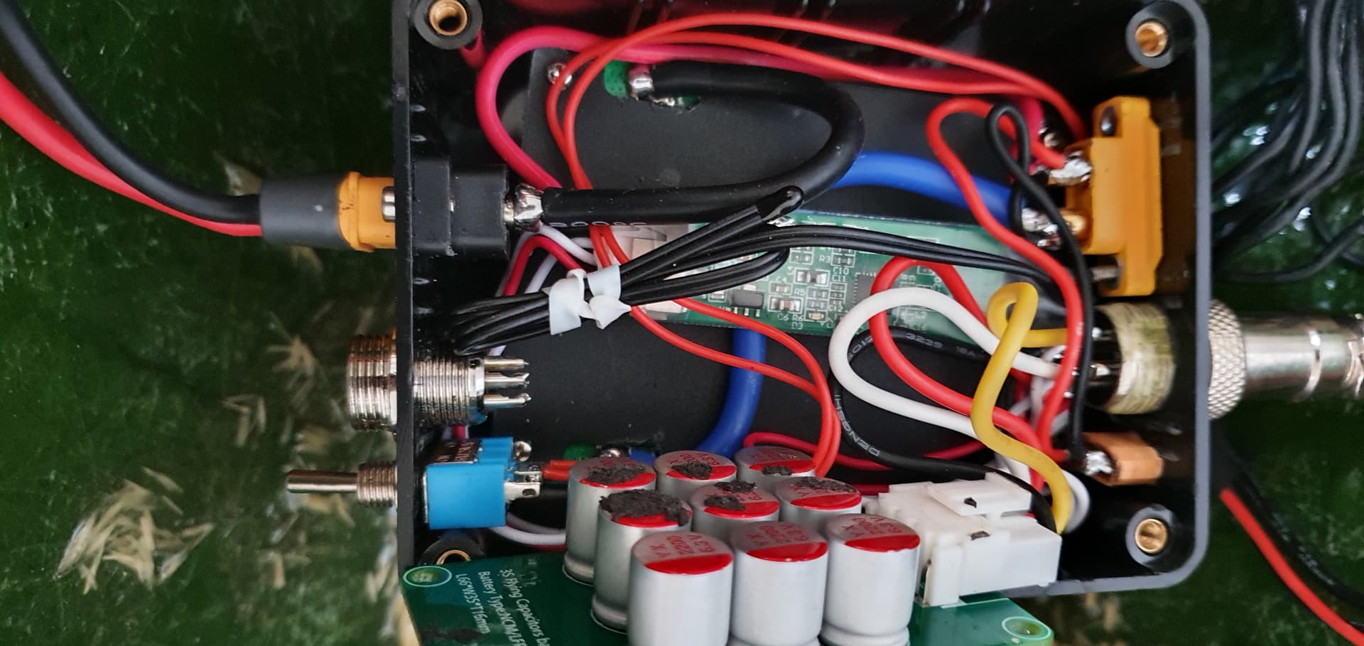
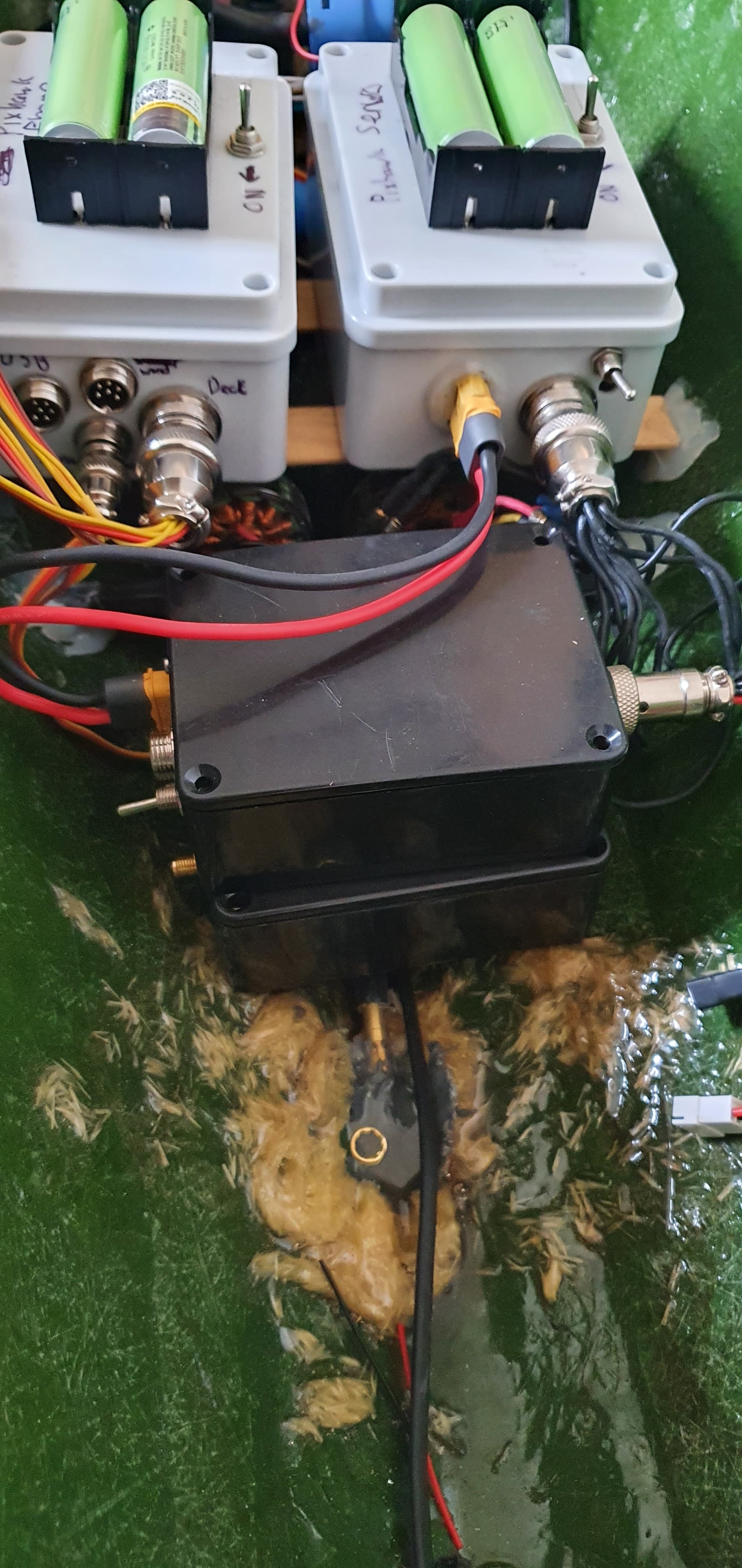
I installed a super capacitor on the servo 5v rail to smooth out any surges and i added a hall current sensor to monitor the current from the thruster pumps.
2 Likes

1 Like
That is super cool, please post updates when you get it working!
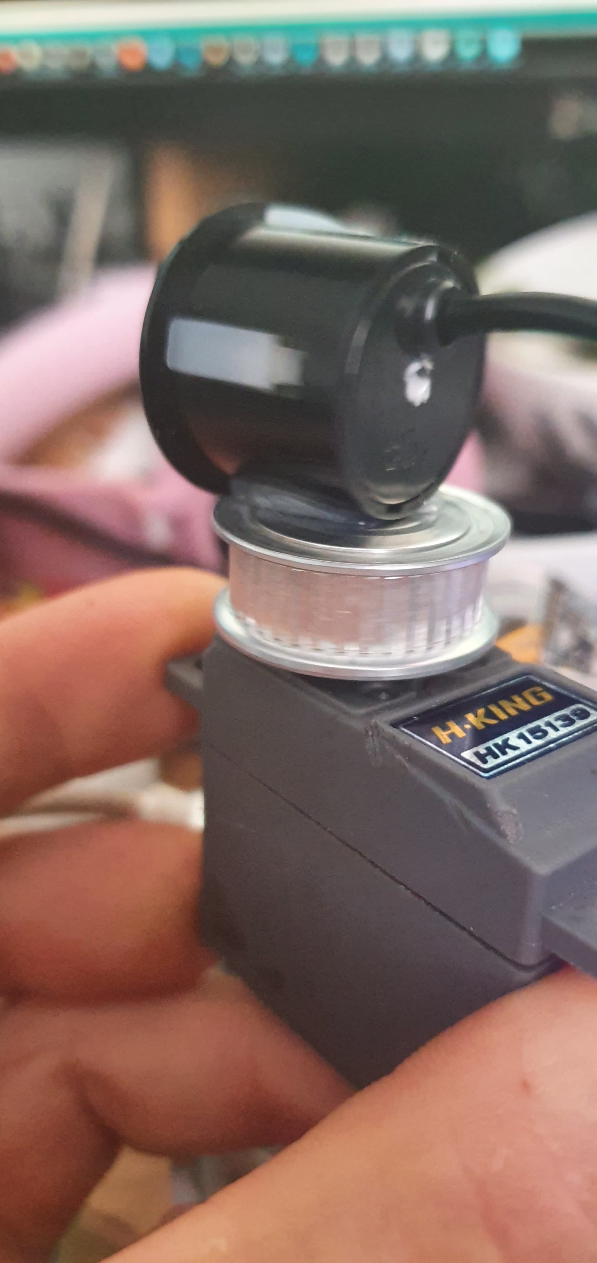
I have shelved the phased sonar for now, its extremely complicated and its going to take time to figure out, so the next idea was a mechanically rotating scanning sonar, using count74s code as a start I replaced the stepper motor code with servo code and replaced the LIDAR code with serial sonar code. This gave me a waterproof rotating rangefinder that I can run in a number of ways. Because im using the feedback pin to set the rangefinder orientation rather than the servo input it means I can use other inputs to drive the rangefinder scan like camera following or direct rc control.
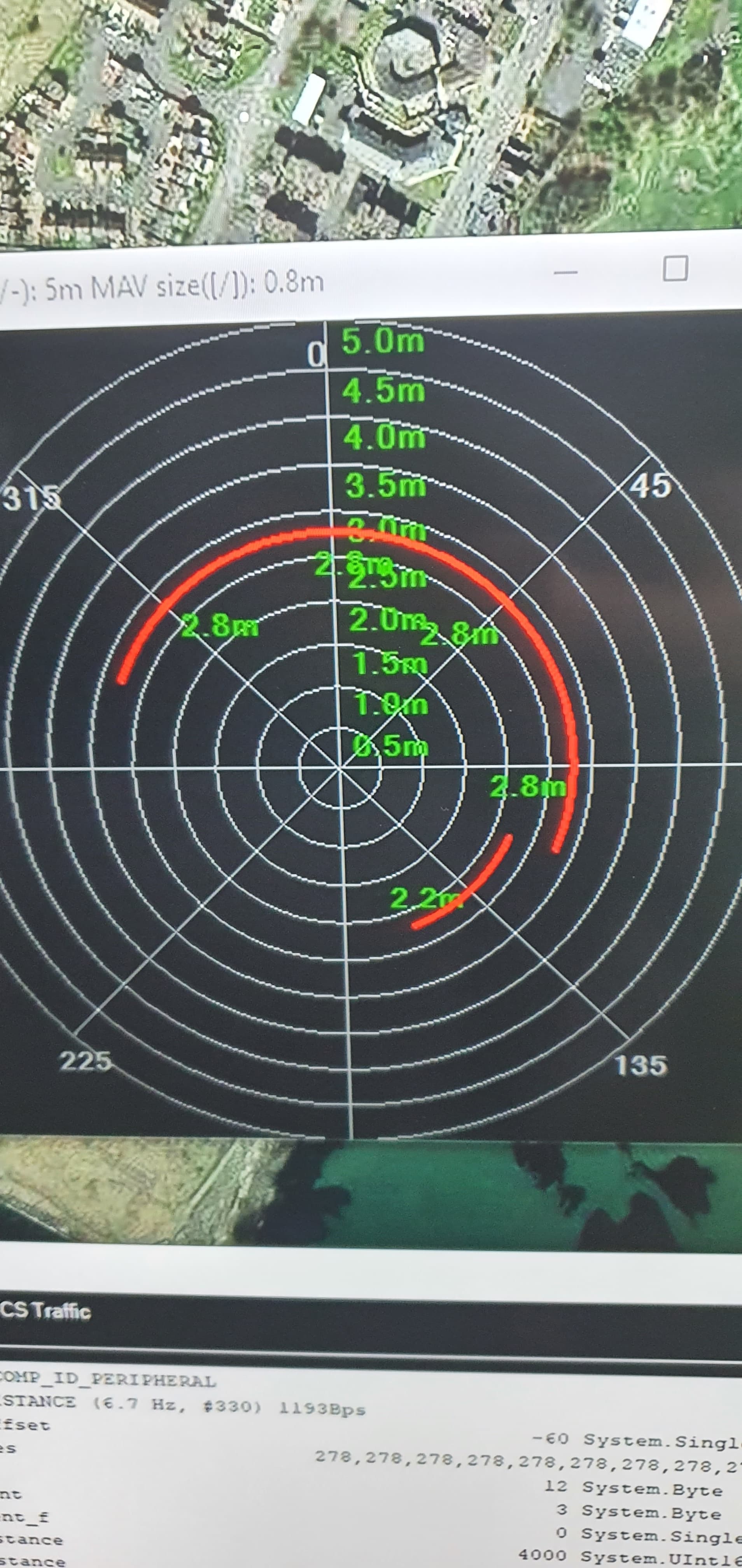
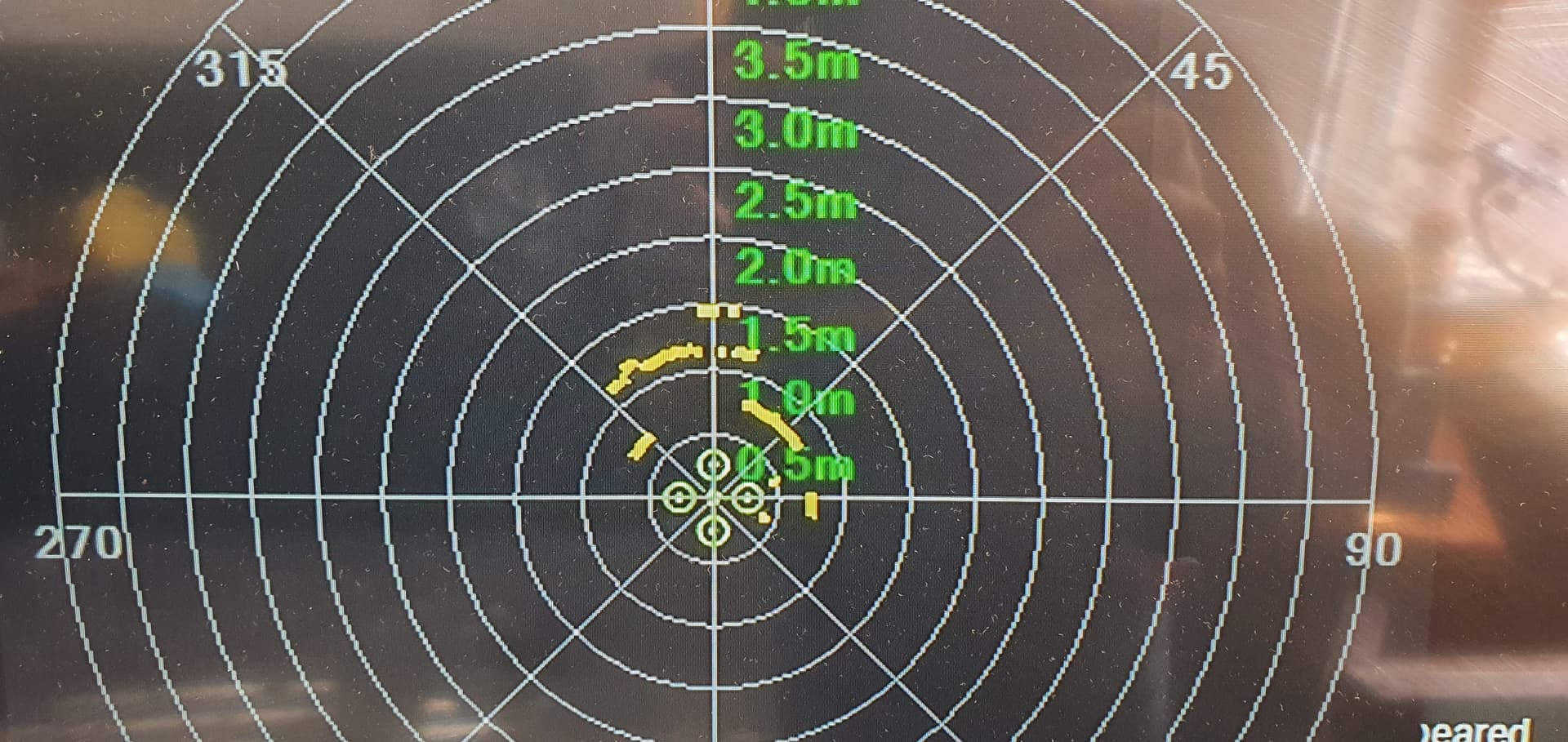
first attempt just got the 8 segments but after adding a heart beat I got the 72 segment
the plan now is to 3d print something more hydrodynamic so when I rotate the sonar transducer the boat doesn’t weave from side to side the plan is to mount the sonar transducer it on the end of a brass tube under the boat driven by a servo using a belt to increase the angle so i can use a regular servo.
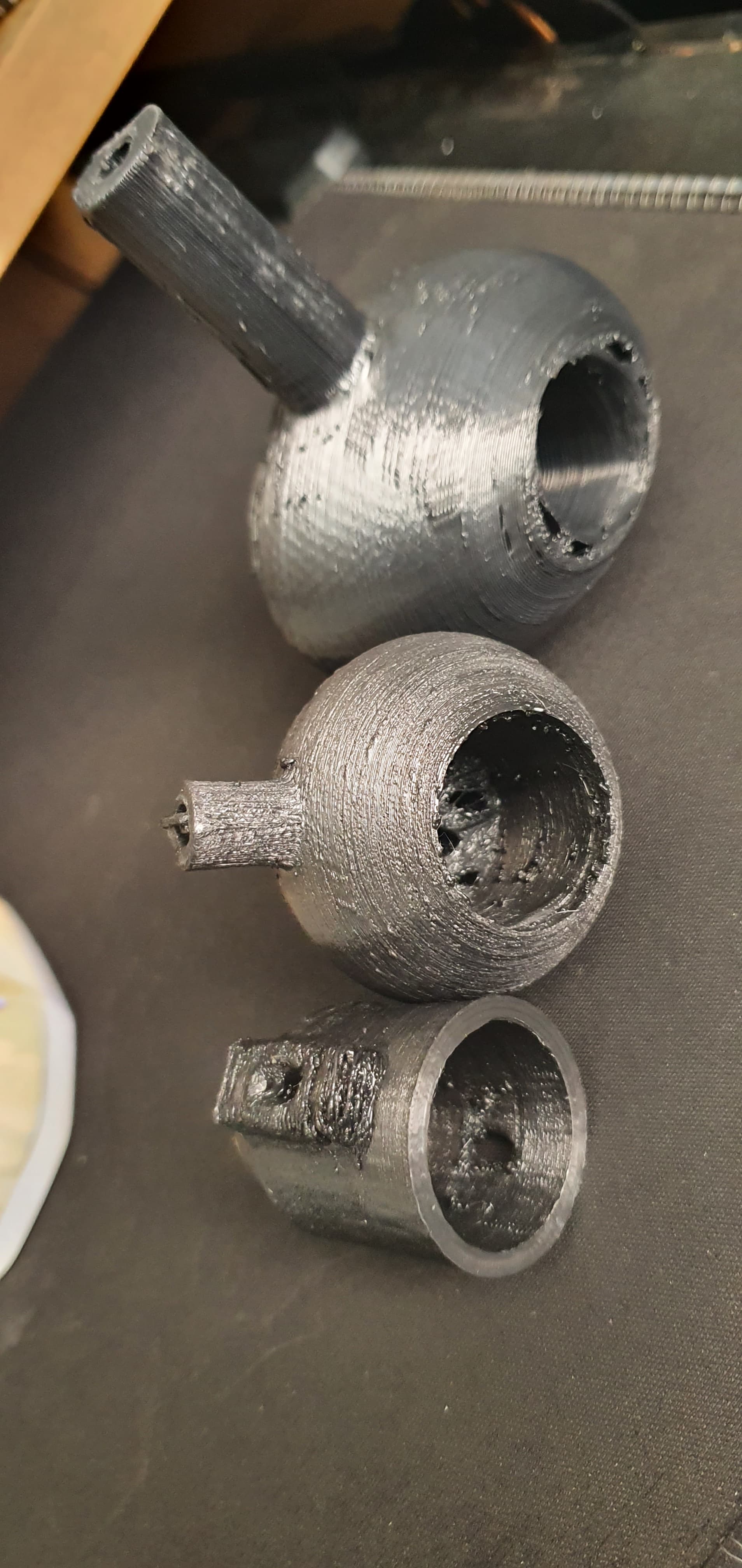
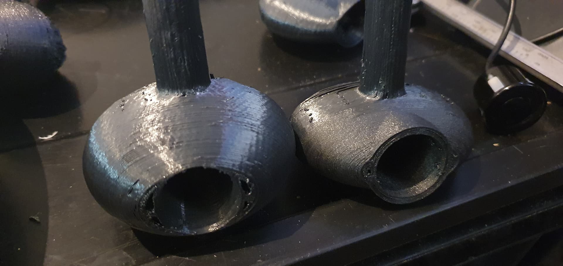
my next design will have the transducer embedded into it rather than on the end, this “tube” should focus the sonar on a much smaller field of view giving much more accurate returns.
1 Like
Great job! It turns out one such bundle (servo and echo sounder) can cover a sector of 180 degrees.
1 Like
The only thing that such a sonar needs to be located at the ends of the vessel.
With it mounted on the front i should be able to get around 300 degrees of coverage before the keel gets in the way using a 1:2 ratio on the belt. I looked at some kind of telescopic system that would let me lower it down under the keel but i couldnt think of a simple way of doing it.
1 Like
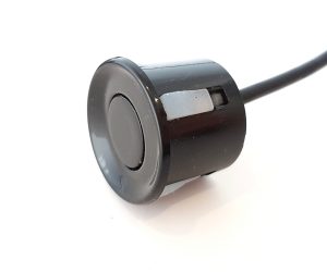
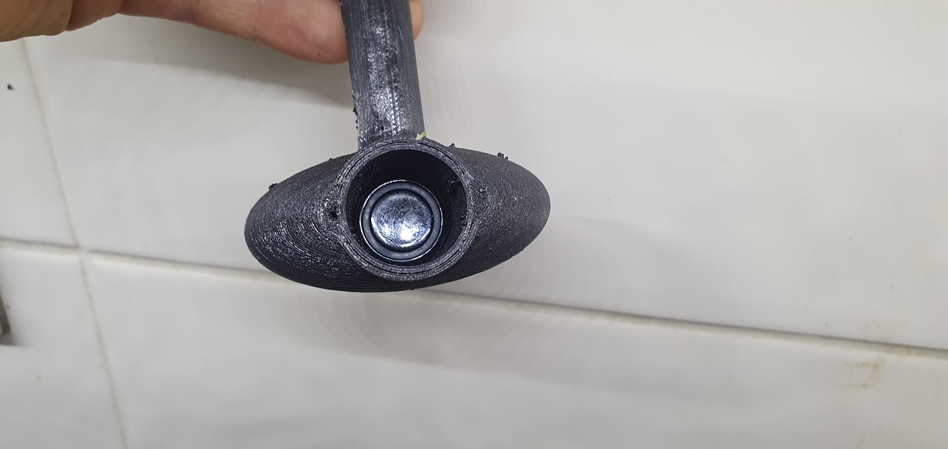
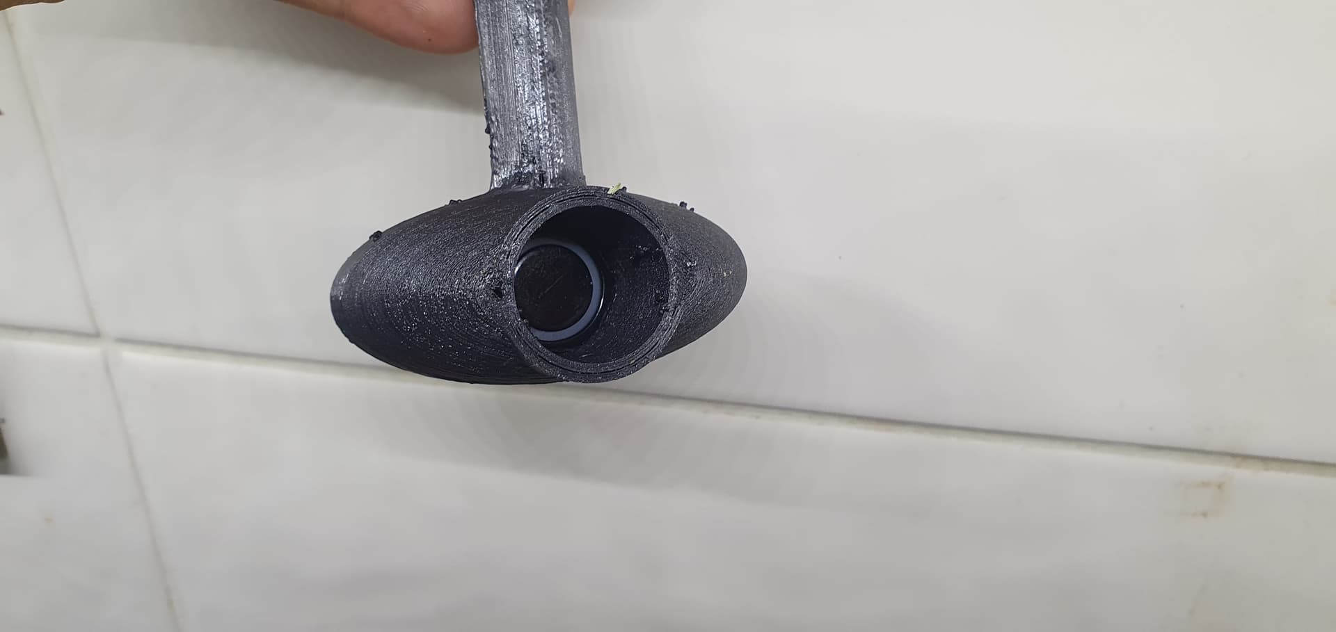
I have a prototype made using a transducer from a AJ-SR04M waterproof sensor. Its very similar to the JSN-SR04 apart from the transducer has a flat face rather than being tilted up slightly making it better suited for this application.
The idea is that by embedding the transducer into the sonar it should form more of a beam giving more accurate ranging.
1 Like
wrote an arduino adapter to hopefully convert the HLD-LD303 Radar to maxbotix i2c similar to how i have done the sonar adapter, its a very short range radar, only 3m or so but it should be ideal for short range on water or as a landing radar or aircraft. i should have more results when it arrives
1 Like