Greetings. I am thinking that the system identification mode will be really useful as it collects much information which, it seems, could then be post-processed and used to help make things “tight” and “right”.
You should look at tuning page then ! You have plenties of data in the log that are waiting to be analysed. As the mode description said, you have recorded the system output to a stimulus. From the log you should be able to calculate if the response is the one you want and if not adjust the different controller to reach the response you want.
If you aren’t used to manipulate those data, you could start be something more basic like a PID tuning. Look on the net the theory behind PID tuning. And I speak about the real math behind PID, not the approximation you could read on drone forum…
But towards the end of each System Identification run, the copter climbed a lot, so we manually reduced throttle. I have a gut felling that we should not have done that. Can you comment on this?
I would also like to add information about system input variables and system output variables for each of the runs to the wiki.
My next action will be to create a script that extracts the relevant SID sections of the flights from the dataflash logs to convert them to matlab files.
That is not a problem. You need to make adjustments to keep the copter in position.
There is no log output. All of them record all the data. So the logging does not change. The rates are defined as presented in the Wiki. You get the ATT, RATE and PID logs with the additional SID log for the excitation reference data. This is all done lock step to ensure the data all has the same time stamp for each sample.
I need the source of that diagram so that I can edit it and send it back to you.
I plan to use diagrams.net to recreate it in editable .png file format so that anyone can edit it.
Can you take a look at the table above? It tries to explain why the axis are there and what they are used for.
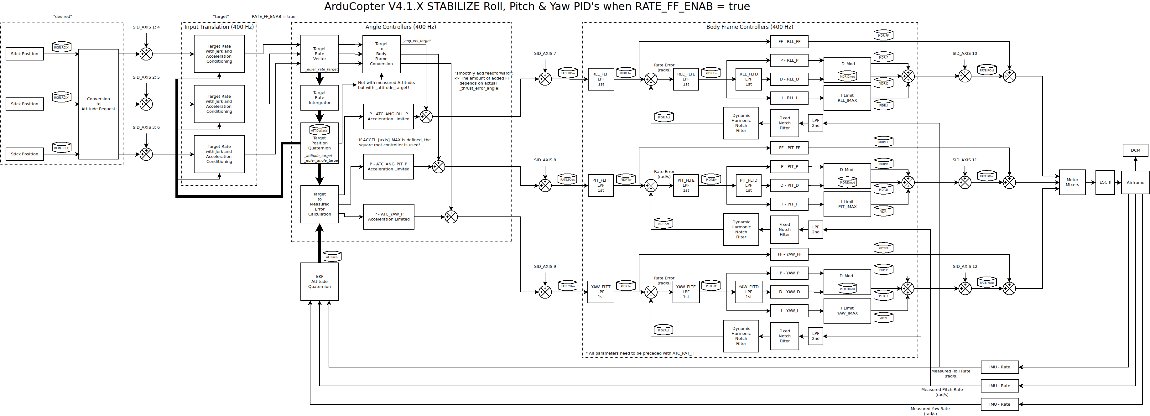
I plan to make that table part of the matlab script documentation, together with the annotated diagram where one can see where the signals get injected and which signals get logged together with their name.
The matlab script posted above is a good starting script for anyone, just feed one or more .bin log files to it and it generates fully annotated matlab iddata objects. And it is documented
So your question marks are actually:
Angle and rate controller and system yaw response without the command model (input shaping)
And the points with:
(no controllers) still have the controllers active so they will fight against your excitation still.
Any of these can be used to create various models the difference is the frequency response due to the filters the excitation pass through and how the controllers fight against them.
I will send the diagram by email as I can’t attach them here. I used Dia.
@Leonardthall here is my latest diagram, just rename from .dia.txt to .dia.
I added notch filters, point where signals get written to the .bin log files, and the injection point for the system identification.
They aren’t in the stabilize controller. They are an outer loop (wrapped around the stabilize controller for position control) and do not affect the response that you are measuring with the system ID mode
It is important to know how the data is filtered before it is stored. This will impact bare airframe identification if it is not fully understood and properly accounted for in the model identification.
I worked a bit more on it and did some corrections.
@bnsgeyer thanks for the input, I now understand why PSC_VELZ_FF, PSC_ACCZ_FF, PSC_VELXY_FF are not depicted in the figure. The figure describes the stabilize flight more, and there is no position controller on that one.
Yes, it is very important to know the source of the logged signals. That is not documented, this is my attempt at documenting it. I hope this helps other people struggling with the SID mode.
@Leonardthall In the diagram, shouldn’t you show that the stick position is converted to a pilot attitude request before it goes into the Input Translation block?
@amilcarlucas SID_AXIS 1, 2 and 3 would be the pilot inputs (stick position) as an angle request which would be before the input shaping (which I believe is occurring in the Input Translation block).
SID_AXIS 4, 5, and 6 would be in the same place as the first 3 however the feedforward is off. So in the Angle Controller, the block that says “target to body frame conversion” would be removed from the diagram.
I am pretty confident that what I said is correct but I would like @Leonardthall to verify that.