Alternate (Academic) Copter Attitude Control: LQR, MPC idea share

I’m working on a multi-input/output (MIMO) learning-lab of sorts: Linear Quadratic (LQ) methods of attitude control instead of the decoupled roll-pitch-yaw PIDs and associated thrust controller. In a MIMO scheme thrust and the attitude axes are coupled in the solution (thrust somewhat less so but that’s my initial topic below).

I also see on here folks who are occasionally interested in model-predictive-control (MPC) for academic work. My LQ interests are a structural basis for any interest in MPC so with this topic I’m inviting any-and-all to discuss these topics and work together on how to structure an approach within the codebase.

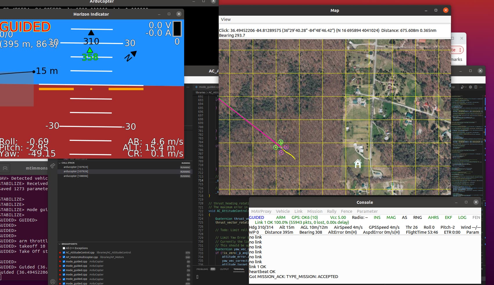
At the point of creating this topic I have on my bench…

  1. An accumulating write-up at…
    This has base theory and various diversions on the electro-mechanical theory side. I also have a nubmer of matlab resources to paper-study work.
  1. A roughed-in AC_Attitude_Control_Multi_LQ class on my bench with #define logic needed to instantiate it instead of the AC_Attitude_Control_Multi class for typical quad.

  2. Sim environment

Matlab SITL sim and MATLAB json listener for some streaming output plotting as I implement LQR schemes (and eventually LQ with roll-pitch-yaw reference inputs instead of regulation to zero)

  1. Questions/challenges…

A) MIMO scheme relies on kinetic model (units matter for now) instead of kinematic design within the codebase. not to say the MIMO scheme can’t evolve similarly BUT the “Academic” starting point of dealing with a physics model produces controller command outputs as thrust and torques, which then map to propeller speeds through to the ESC…mapping all this to the “motors” output logic needs some work from me still.

B) related to this, “Thrust” is presently decoupled as the z-controller’s output into attitude control, albeit with some, “boost” logic to account for roll-and-pitch but as-is base-level thrust for hover PLUS acceleration in Z is an input to attitude control.

LQ attitude controller output of roll-pitch-yaw as torques from a system of 4 propeller speeds is solveable as

Aw=T
where…
T is a 4-element vector [Thrust, Troll, Tpitch, Tyaw] (command outputs)
A maps prop speeds to torques through thrust and drag coefficients and quad lever arm.

w is solved for given controller output vector T. w is a 4-element vector of prop speed squared for props 1 to 4.

I’m starting this topic at a conceptual stepping-off point and would love some advice…

  1. I can let the existing Z-controller operate independent of attitude control and accept the unitless “thrust” output as input to my attitude control.

-I then need to figure out how to scale it into the first element of my T vector above, while the remaining 3 elements of that vector are from my LQ controller output.

OR…
2) I pull Z-error into my AttitudeController and generalize my thrust reference as a combination of minimum for hover (overcome g in z) and any additive acceleration in Z, X, and Y.
-This gets a bit logically “circular” because X-Y accelerations are achieved through non-zero roll and pitch reference inputs.

I’m thinking of starting with method 1 above as I implement LQR (goal is to regulate roll, pitch, yaw to zero)

Past that when roll and pitch reference inputs are desired it implies the high-level command involves X-Y-Z accelerations which are not decoupled and then I might pull thrust into my attitude controller.

Think of the reference input as the body Z-axis relative to Down. Magnitude representing desired total thrust and directions implying desired lateral accelerations with the up component representing local NED vertical acceleration command.

hover=g, ascend >g, descend <g so there is always a non-zero vertical acceleration that, with a mass estimate is the vertical thrust.

A combination of body X,Y, and Z accelerations is represented by this vector and I think then I might be tripping over myself if I let the independent Z-axis logic run as an input to my attitude controller.

I’m rambling though…still wrestling with how to fuse thrust and attitude control in a baby-step fashion that doesn’t discard too much existing value in the codebase.

Any advice would be nice…I might be over-thinking at this point

2 Likes

Hi Mike, I’m also interested in implementing LQR and iLQR controllers onboard. In fact I did some implementations on PX4 stack with Eigen that I’m cleaning up recently. My approach is to replace the whole PID control stack with single controller that takes reference path and current state and outputs thrust and torques. I tried to read your post but lost in the middle. Maybe it would be better if you could modify the existing schemes and show where exactly you want to put LQR control (what parts to replace):
https://ardupilot.org/dev/docs/apmcopter-programming-attitude-control-2.html
https://ardupilot.org/dev/docs/code-overview-copter-poscontrol-and-navigation.html
or with PX4 diagram which a bit more compact
https://docs.px4.io/master/en/flight_stack/controller_diagrams.html

BTW Your resources looks great, especially those describing low-level stuff. I’m going to read through it

1 Like

I did some updates on the ardupilot diagrams here:

I’m also working on this, but not to create a new controller, but to optimize the parameters of the existing ones

1 Like

What I have on my bench (running as sim using SITL matlab sim and SITL data plotting to Matlab) is a replacement for AP_attitude_control_multi which I name AP_attitude_control_multi_lq. I then tweaked a few defines so that this becomes the attitude controller class “copter” instantiates and calls via, “attitude_controller_run()”.

Step 1 I just left it as an exact copy of the PID attitude controller. This way I can incrementally introduce my u=-kx command output while still letting the PIDs run. When signs and control outputs look proper on my real-time plots I can swap the control logic from PID to LQ. This is all within the attitude controller.

The hang-up I describe above is that the attitude controller takes a pre-computed “thrust” scalar (zero to 1) for each motor based on a Z controller. Then the attitude controller plus-minuses this based on PID desire for roll, pitch, and yaw.

Then “motors_out” further scales the scalars for Vbat derating, etc.

It’s all very elegant and perfectly sensible for the extremely flexible/adaptable nature of the codebase.

However, the unitless nature of it all becomes a bugger given my physical model starting point.

Since my post I have resolved to do this:

  1. I’m going to work the Z controller into my scheme so that…
  2. my 4 equations in 4 unknowns Aw=T (I need to write this up to explain better) can solve for…
  3. 4 motor speeds given body Z-axis aggregate thrust command AND roll,pitch,yaw torque commands that result from the u=-kx command output from the controller.
  4. characterize my esc-motor-prop assemblies so I have a map of PWM-to-prop speed
  5. short-circuit current, “motors_out” logic to just drive my computed PWMs to the ESCs without additional scaling in that call stack.

Steps 4 and 5 defeat a bunch of value in the codebase. I’ll very likely eventually recover all that value. However, given my somewhat, “academic” interests I don’t want to lose my units and get all confused with various zero-to-one scalars operating on my command output. I’ll get too confused.

I’d like to buy a thrust stand. “turnigy” has/had one for near $100. There’s a much better one at the link below but I don’t think I need the quality it offers for $625…looks like the Tunigy is discontinued though.

fancy ($625)

my style ($100)…but I’m having a difficult time finding one…

Interesting stuff.

One of our users describes a home built thrust stand here

1 Like

Interesting stuff.
Re using units: is your LQ controller going to interface directly with AP_Motors? If so, AP_Motors expects a normalised thrust (0 to 1) from which it determines a throttle and subsequently calculates the PWM to send. You would therefore be better of doing the conversion of your system of equations to be normalised in the same manner. That way, it saves you the hassle of converting the thust to have units to pass through your controller to then re-normalise again to pass to AP_Motors. Or, have I missed the point and you are in fact going to write your own equivient of AP_Motors?

Re thrust stands. There are many low cost options around. Here is another one:

I think the key issue with the low-cost thrust stands is that they tend not to offer logging. So your experiment is reverted to good old fasion pen and paper (having read it from the display).

2 Likes

Thanks Matt! My confidence problem is the mapping into zero-to-one for thrust. Actually, as-is the attitude controller has a unitless aggregate thrust given to it by the Z controller, and native attitude control PIDs determine individual motor thrusts relative to that. Then it looks like motors output does some Vbat derating before getting to a PWM setting to drive the ESCs.

So at this point if I characterize my motor and prop, and possibly my own Vbat derating then I have a thrust-to-PWM out map directly.

As I look some more it will be my preference to do as you recommend: figure out how to use the zero-to-one scalar and just let the motor output calls stack do its thing. We’ll see.

Thanks for the thrust stand link! I’m cool with pencil and paper given my low run volume. The $600 stand an software looks great but it’s a little rich for me at this point.

After some off-and-on efforts this winter and spring I finally have my LQR scheme in-place for attitude control and I am simulating on the bench using the SITL Hexsoon Matlab model running on my PC matlab instance.

I struggled for awhile with my units, having a “kinetic” model and needing to derive motor commands from the LQR’s body torque command outputs: roll, pitch, and yaw torques.

I over-thought things for a bit: I mapped the Z-controllers 0-1 normalized thrust to a thrust with units and then solved for four motor speeds, having now 4 equations in 4 unknowns (3 torques and Thrust, from which to solve 4 motor speeds.

But then I was still wrestling with now to cram those back into the resident motor code. I will likely revisit this but it will require picking apart motor code to cram my speed solution into the PWM nearer to directly.

I backed out of this corner though. Instead I realized I could skip the speed solver and just normalize the controller body torque outputs.

Here’s the basic attitude controller now…

// state feedback is angles and rates
x[0] = q.get_euler_roll();
x[1] = gyro.x;
x[2] = q.get_euler_pitch();
x[3] = gyro.y;
x[4] = q.get_euler_yaw();
x[5] = gyro.z;

// reference inputs are desired angles and zero rates

// this HACK divide-by-10 on taget roll and pitch is temporary as I was going unstable
r[0] = _euler_angle_target.x/10;//_attitude_target.get_euler_roll()/10;
r[1] = 0;
r[2] = _euler_angle_target.y/10;//_attitude_target.get_euler_pitch()/10;
r[3] = 0;
r[4] = _euler_angle_target.z;//_attitude_target.get_euler_yaw();
r[5] = 0;

// 6x4 controller gain _k and reference input gain _Nb matrices are read in from files at present

// This isn’t LQR, it;s just LQ, as we’re not regulating to zero but servo’ing to reference inputs for body
// roll, pitch, yaw as given by the position controller outer loop.
for( int i=0; i < AC_ATC_LQ_CMD_COUNT; i++){
cmd[i]=0;
for( int j=0; j < AC_ATC_LQ_STATE_COUNT; j++){
// the -k*x is the regulator solution, the reference tracking is covered by the second term.
cmd[i] += -_k[i][j]*x[j] + _Nb[i][j]*r[j];
}
}


// after the above produces body torque commands I skip the motor speed solver idea for now and
// just normalize and use the set_ commands into the motor infrastructure…

// estimate a theoretical motor speed max from Kv and batt voltage. This over-estimates as it ignores prop drag.

_wmax = _phy_kvAP::sitl()->batt_voltageM_2PI/60;

// square _wmax for a couple uses below.
wms = _wmax*_wmax;

// max roll and pitch torque estimate is thrust factor _b times arm length and squared motor speed, which simulates max thrust from one motor with the opposite motor off
Tmax = _b*_phy_armlen*wms;

// max yaw torque is drag factor times two motor speeds squared, akin to having two same-rotation motors at max while the other pair rests.
Ymax = _d2wms;

// Then I just normalize controller command outputs and inject -1 to 1 scaled commands into the motor scheme
nroll = cmd[0]/Tmax;
npitch = cmd[1]/Tmax;
nyaw = cmd[2]/Ymax;

_motors.set_roll(nroll);
_motors.set_roll_ff(0.0);
_motors.set_pitch(npitch);
_motors.set_pitch_ff(0.0);
_motors.set_yaw(nyaw);
_motors.set_yaw_ff(0.0);

With this I’m at least stable and can “fly” to new points on-screen.

Some NEXT steps (I’d love any ideas or for anyone to hit me with more items to consider):
1)I need to refine the position controller’s establishment of target “lean” angles to resolve my have downscale of 10 above.

-I have some rough gain factors above with the normalizing of torques and need to take stock of my gains now.

  1. bias estimation (integrator) as I expect small signal (torque command) behavior on the actual flyer will be an issue. I should be able to hack my sim to create this situation in a controlled axis-by-axis manner and get the proper structure in-place (bias estimation or state integrator). That said, I haven’t pondered this enough yet.

  2. some refactoring…This is all done in a single (new) class “AC_AttitudeControl_Multi_LQ” which is running in-place of AC_AttitudeControl_Multi.

  • if/how to get a pull request in and how a build configuration option for a quad might work.
  • I’d like to enable anybody interested in this topic.

3.1) resolve best way to load/modify gain matrices (the 6x4 gain and reference input matrices). This includes later having a look-up table for these because technically they’re a function of where in the flight envelope the copter will be. For example, and acro-style drone with considerable body rotational rate. This modifies the state transition matrix ‘A’ and therefore would change controller gain K.

3.2) It’s somewhat academic, and definitely for small-signal behavior near hover, but I’ve thought of a look-up scheme indexed by body rotational rates as a “gain sliding” method. This involves off-line solving the matrix Ricatti equation (matlab’s lqr() command) and then loading as part of resolving item 3.1 above.

  1. Supporting Theory:
    4.1) state-space modelling

4.2) reference input methodology:

  1. Get back to my 6 DOF test stand and prep for some live hardware testing.

For now, I’m happy to be stable on the simulator as a basis for more understanding and refinement

1 Like