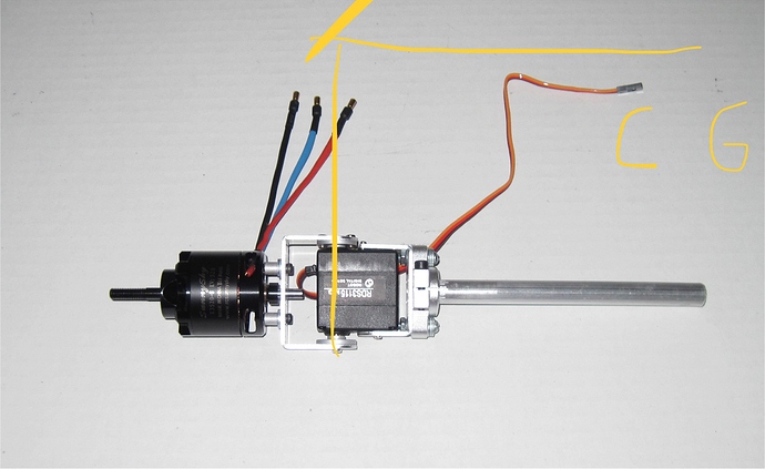
OK Greg, I think is better 19,5mm (6") between the CG and tilt servo shaft. It will be easier to balance CG although the propeller overlaps more over the wing
I must have been brain dead when I connected the throttle because I connected the stock “Y” cable to output 3. You need to split the throttles apart and connect the left ESC control to output 6 and the right ESC control to output 5. My setup seems ready to add the props and do a final alignment. It is rainy and wet today but I should be able to try a hover test tomorrow (Sunday). Fun stuff!
My wife took the grandkids to get pumpkins so I seized the opportunity to put the props on and go for a backyard test. Guess what, it hovers! 
I’ll look to get some photos or video tomorrow. All the stick directions seemed correct so I moved it out into my backyard that has lots of tree and bush hazzards. In QSTABILIZE mode I seemed to have good control. One issue seen was a back and forth yaw movement which was being done by the front motors slowly yawing maybe ±5 degrees. I am used to quadplanes or my FF6 that uses motor speed for yaw so I am not sure what parameter I can tune to reduce this issue.
That’s awesome Greg, have you had a chance to try QLOITER?
I have managed to get rid of most of our tail wag with the following params:
Q_A_RAT_YAW_D,0.02
Q_A_RAT_YAW_FF,0.003
Q_A_RAT_YAW_FILT,5
Q_A_RAT_YAW_I,0.08
Q_A_RAT_YAW_IMAX,0.333
Q_A_RAT_YAW_P,0.8
It’s not perfect but the tail is almost now without any yaw variation.
Graham,
Thanks for the parameters! I’ll give them a try tomorrow. I only use QSTABILIZE initially in my backyard because it is a very small area surrounded by trees and an upper canopy. When ready, I’ll take it to the park and check the BARO and GPS modes. I had three hovers today and it’s still in one piece so I was happy.
Cheers!
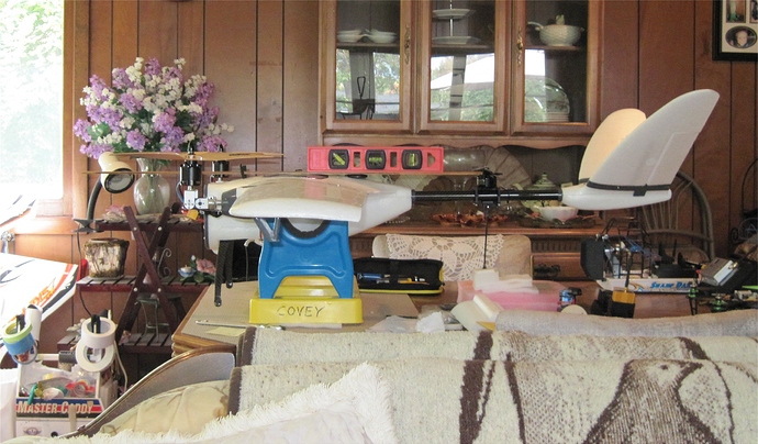
After my intial hovers, I decided that I never really did a good job aligning the front motors so I used a yard stick and a level to fine tune the front motor up and forward positions. The tail boom, level, and front props are all in alignment now.
Since I am likely to take off the props during my test, I didn’t used the 6mm lock nuts but used the nut and spinner that came with the Sunnysky motors for easier removal.
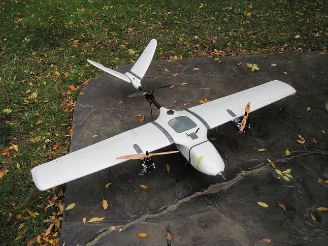
My initial hover testing of the DIY Nimbus 1800 VTOL in my backyard went well using QSTABILIZE and QHOVER modes. The local fields were busy so I went home to my backyard.
Although I used Graham’s Q_A_RAT_YAW settings, there is still a vectored yaw oscillation that needs to be dampened. I did try a bunch of different settings without being able to eliminate the waggle.
After a considerable amount of hovering, I felt the motors and ESCs. The motors were cool and the ESCs just barely warm. It was a good start that validated many parts of the setup!
I found some posts about vectored yaw by @Rolf and @tridge in the Tiltrotor support for plane thread. There is a parameter called Q_TILT_YAW_ANGLE that may need to be adjusted. I think mine is set to 13 now. I am not sure what effect this will have on the wobble but it seems that something other than the Q_A_RAT_YAW settings may be at play here.
I had to increase these values to avoid that yaw movement in one X8:
Q_A_RAT_YAW_I = 0.07
Q_A_RAT_YAW_P = 0.9
You can try.
Thanks, Atico. I’ll give them a try…
I did some more digging and found out that other Nimbus 1800 VTOL conversions are using 6v on the tilt rotor servos. The UAVS conversion embeds a 6v BEC in each wing for the tilt rotor and aileron servo power. The FoxTech FPV V2-Tilting System uses servos that require a minimum 6v supply.
The RDS3115MG servos that I am using have the following specs:
- Item: RDS3115
- Angle: 180 degree
- Maximum PW: 500-2500μs
- Working Voltage: DC 4.8-7.2V
- Operating Speed: (4.8V) 0.16 sec/60°
- Operating Speed: (6.0V) 0.14 sec/60°
- Stall Torque: (4.8V) 13.5 kg.cm
- Stall Torque: (6.0V) 15 kg.cm
- Stall Torque: (7.2V) 17 kg.cm
- Dimensions: 40X20X40.5mm
- Weight: 60g
- Gear: 25T
I’ve decided that I will add a new 6v-7v BEC to power the tilt rotor servos and keep the existing 5v BEC on the Pixhawk servo rail so I can also have backup power. The Pixhawk can be powered off the servo rail instead of from a power module if the power module fails.
Increasing the voltage to the tilt rotor servos will increase their speed and strength so the Q_A_RAT_YAW settings will be affected. Hopefully, this change will eliminate the yaw wobble.
Distance between CG and servo tilt shaft (if the CG is 100 mm from the leading edge):
I said it’s better 195mm but I’m still wondering if it would be better one inch more as Foxtech kits
Maybe it’s because they do not carry weight on the nose?
Whart do you think about?
Both VTOL versions (UAVS and FoxTech) seem to work but I have not seen one with a camera up front yet.
For my second hover test, I supplied the tilt servos with 6v and they were much stronger and faster than before. I also tested QLOITER mode in my backyard which checks out the BARO and GPS functions.
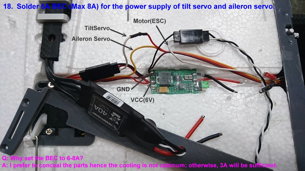
My new plan is to install 6v BECs in each wing to power the tilt rotor servo and aileron and use a 5v BEC on the Pixhawk Output/Aux rail with a 5.7v zener diode for backup power if the Power Module fails.
GregsNimbusHover3.param (16.8 KB)
Glad i helped 
If servo support it try it at 7,4 volts (2s direct) they should do even better.
Since the yaw is now controlled by servos movement i think some D gain would make wonders for the bounce.
Corrado
Hi Corrado,
Yes, I agree. Unfortunately, it would make wiring through the wing connector more difficult. To ease the wiring, the 6v BEC is shared with the aileron servo to free up a wire to the wing connector. In this manner, you can more easily swap out the wire function from +5v to tilt servo control without actually cutting the wing and fuselage foam. The stock aileron servo may need to be replaced in order to handle 7.4v. So it becomes a possible upgrade for the future…
by just changing the power of the servo tilt-rotor have you managed to solve the yaw movement of the first test?
First, congratulations
Greg, I asked about the distance of the new foxtech kit between the servo tilt shaft and the CG (understanding that the CG is 100mm from the leading edge) and you answered that about 220mm.
in your system til-rotor for these tests, what distance do you take?
Correct. I started with Graham’s PIDs from before and it worked much better so I gambled on testing QLOITER mode in my backyard…which is risky with the limited space and top canopy of tree limbs. It seems that all the conversions are using 6v on the tilt servos so my next step is to install BECs in each wing to hide my wires.
My setup is still using the 6" (152.4mm) aluminum tubes. I am keeping the FoxTech kit as a backup solution. Although more expensive, it is very well designed but wasn’t available when I started my project.


