Hi Greg: sorry to bother you again but what does input-SB chan5, input SA chan 6, and input SC chan 7 what do these do? thanks Butch.K
Hi Butch,
I’m not sure what all your questions are about so I will try to answer them by pointing you in the correct direction.
The QuadPlane flight mode descriptions are here. Initially, you want to use the three modes below to test hover capability. QSTABILIZE mode hovers with only pilot controls. QHOVER adds the BARO sensor for Altitude Hold and QLOITER adds the BARO and GPS sensors for Position Hold.
The normal plane (forward flight) modes are here. I would typically use these three below initially.
If you want to only use a single 3-position switch on the Taranis (until you figure out the mixing for two switches), I would use QSTABILIZE, QHOVER, and FBWA modes.
Since Mission Planner is unaware of Taranis switch labels, this seems like a Taranis question about the OpenTx Companion setup. This simply assigns a switch to a channel on the SBUS which goes into the Pixhawk. When you do a Radio Calibration, the Max, Min, and Trim settings get saved in the RCx parameters.
I hope this helps…Cheers!
Good Morning Greg:I put together a mock VTOL using the same components that i’ll use on the nimbus ie=pix 2.1.,Taranis Tx&Rxv ,i used servos for ail’s&V tail and 2 servos for the tilt motors hooked all up with a PDB 3esc’s and motors with 5v ubec on the pix aux rail for the 2 tilt servos and when i power this up nothing works ? i pushed the button on the pix the lite is solid (armed) but none of my switches on the Tx doesn’t do anything that is why i asked how do you arm the nimbus? is their a switch or setting in the Tx or a setting or Param in MP that needs to be set IDK, I contacted Fox Tec that sells the Nim vtol already put together RTF but the responded back this morning they would not sell me the SD card that comes with the Taranis and Nim vtol rtf since i hadn’t bought the nimbus vtol from them so i’m “SOL” , I have Extreme Surfer Plane at home in Pgh,Pa, but I’m now in Fla for the winter that i put a Pix in and it wouldn’t arm unless the flight mode was in manual and all switches were in up position or off and use the rudder down and right to arm then you got like 10 seconds to start it up same as all my Drones. So maybe please would you send me your Mission Planner files, Parameters cause i don’t know what should be on,off set at this or that etc. sorry but i’m just a old retired guy learning a hobby.Thanks Butch.K
If you activated the Arming Switch and do not get servo movement from the transmitter sticks, my guess would be that you have a problem with the SBUS connection between the receiver and the Pixhawk, or that your receiver is not bound to the transmitter.
The easiest way to determine your issue(s) is to connect Mission Planner via USB or a telemetry link.
To arm the motors, hold the yaw stick to the far right. If your yaw channel happens to be reversed, hold it to the far left…and eventually fix the reversal. It’s all in the Wiki here.
The parameter files have already been posted a dozen times above but here they are again.
Good luck!
NimbusVTOL_SDP33_Flight3.param (17.1 KB)
Thank You Greg: i’m printing them out to go over with whats on my MP params and will change them if needed,Thanks again BK
Hi,
I’m having issues when auto landing in VTOL mode at the end of a mission. Transitions are uneventful, but just after touchdown, the aircraft bounces back up and attempts to land again. Sometimes it just pitches up, with the front landing gear in the air and the rear one on the ground, almost like a horse.
I’ve posted the issue in detail here: Issues (bouncing/balloning) with auto landing in VTOL mode - Nimbus tricopter VTOL
Appreciate any help, thanks!
Hi Greg:I got the params all changed, everything seems to work,except the Rudder so i arm it,only the rear motor starts and then i use the throttle and now all 3 motors are running, then i place it in QHover and the tilt motors seem to move forward to 70 degrees , then FM FBWA motors go down to forward flight but all three motors are still running ? then i reverse that back to QHover motor tilt goes up to 70 deg and then back to Q stablize motors back up to 90 deg throttle down left and right motors stop, but the rear motor will not stop till i disarm Humm what do you think? thanks B.K
Greg i;m getting ready to order CF Props what size for front and rear ? along with 8-26v SBEC for the tilt motors, Thanks B.K
Need some help to figure this one out:
Pixhawk 2.1 Cube (Black)
Firmware 3.9.10
MP version 1.3.68
Nimbus 1800 VTOL airframe
Using an I2C expansion board
Using Here GPS
RFD900x
Using Motor/ESC combos that Foxtech uses (version 2 setup)
Mauch PL series current sensor with Mauch BEC (which is also giving me problems)
Power supply is a 6S 8000maH 10C
It’s not fully configured and it has never hovered or flown yet
GPS, Radio, Magnetometer and Accelerometers are calibrated and work fine until I try to use this sensor
Full Parameter File Here: Nimbus VTOL V1.param (17.0 KB)
Problem: I have an SPD3x airspeed sensor that will not work (will not report any airspeed changes)
What I’ve diagnosed so far:
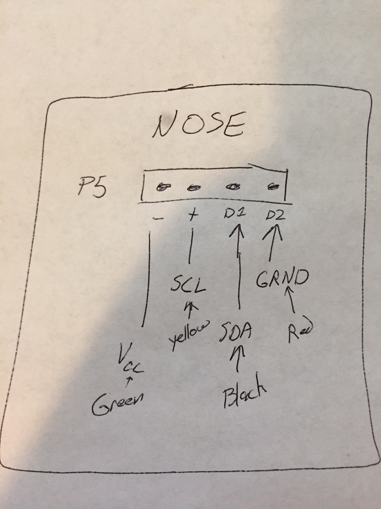
- I used a multi-meter to confirm pin outs on both nose and body and those appear to be lining up correctly as follows: Nose side - + D1 D2 match body side - + D1 D2 and the pin outs of the SPD3x are - is Positive Volts, + is SCL, D1 is SDA and D2 is Ground.
Color scheme is as follows:
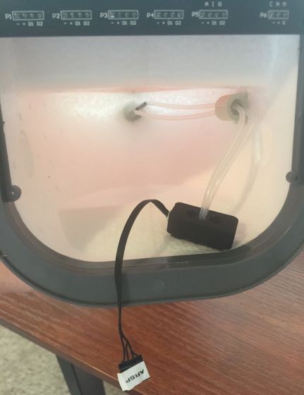
- If I use a regular JST-GH connector (like the one that comes with the SPD3x and plug the SPD3x directly into the I2C port on the PH2.1 (and thus removing any possibility that it is a body to nose cable problem) IT DISABLES the GPS! By disable I mean it looks like it is browning out the whole HERE GPS unit and no GPS gets to Mission Planner. Again, this is by doing a direct connect with a normal connector shown below that I bought a 10 pack of back in the day:
-
Due to the airframe design I am unable to have the SPD3x connected during bootup and I do not know if that is a problem or not.
-
In case it matters I hooked up the ESCs and servos according to this and I have not proven if it is correct yet as I want everything else to be working first:
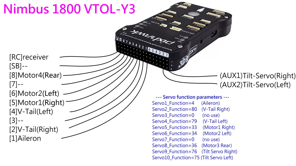
It is configured as shown below:
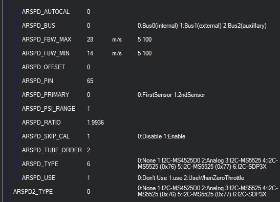
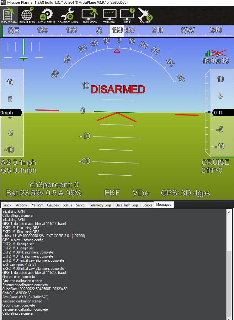
And shows this on the HUD:
I have used this sensor before on a previous VTOL build and after changing the ARSPD Bus variable to 0 it worked perfectly. A comparison of the parameters between that working airframe and this one reveals no help.
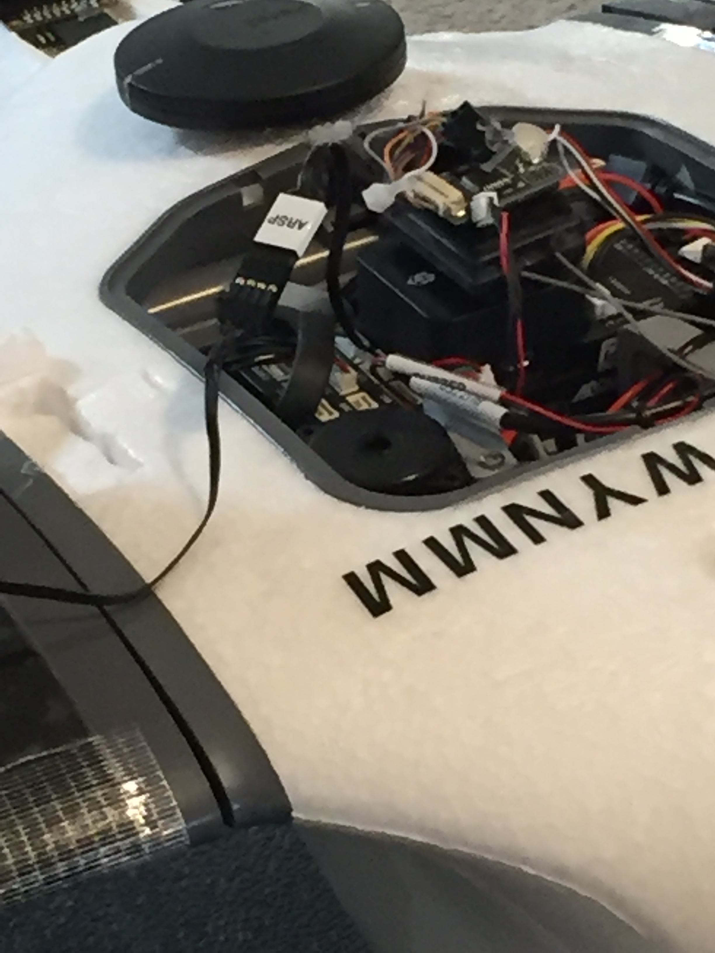
Here she is so far:
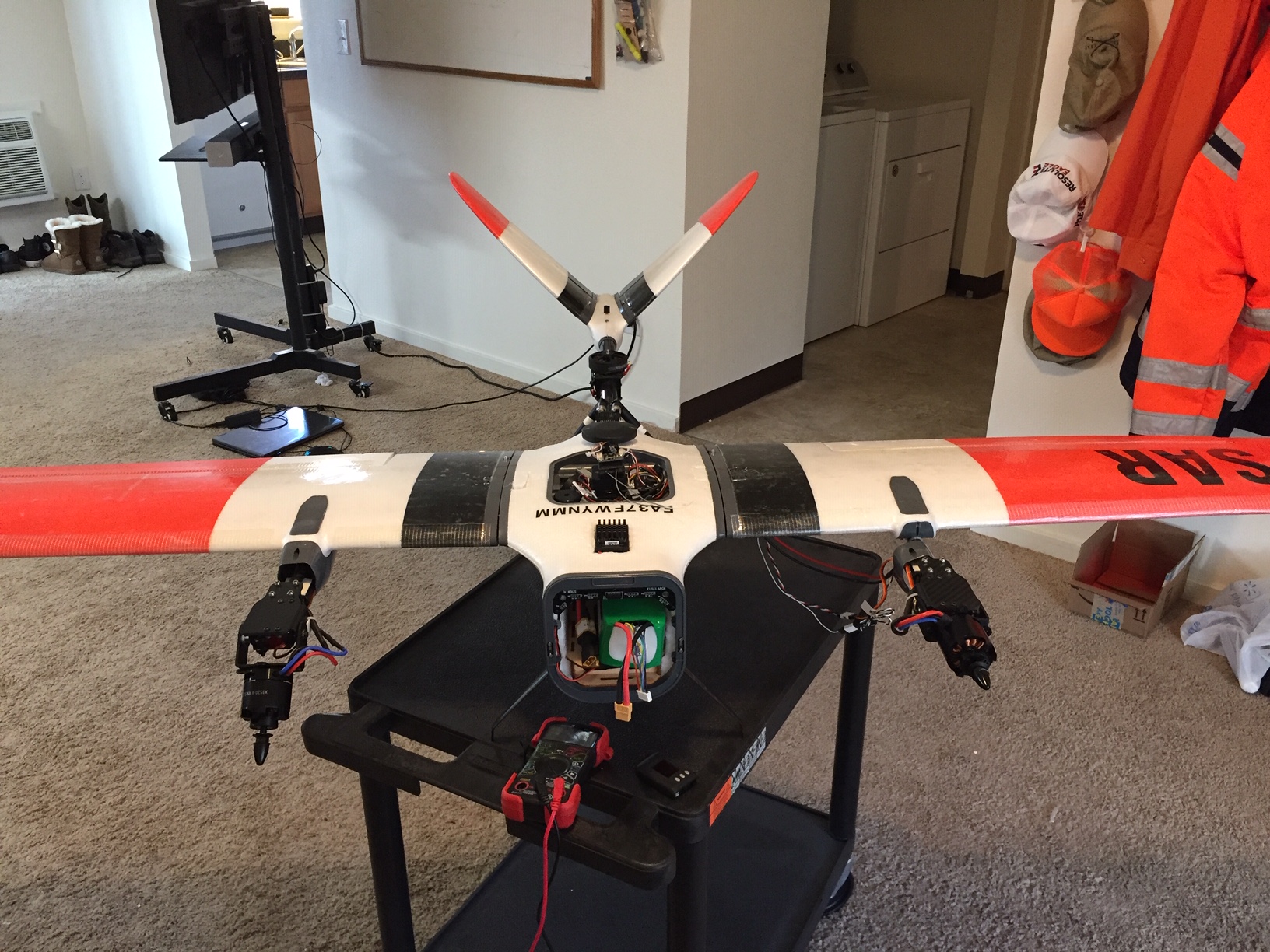
I’m stumped!!
Butch,
Use QSTABILIZE mode to do your ground testing. What you described sounds ok. If you don’t want the motors to spin when armed at lowest throttle then set Q_M_SPIN_ARM to 0.0.
As for prop sizes, I don’t remember what you are using for motors. Most of us are using the 13x8 Wood Prop Set from FoxTechFPV on the front motors because you need the higher pitch for forward flight. I’m using a 16x5.5 carbon t-style prop for the rear but that size depends upon the motor you are using. Refer to the posts above or follow the FoxTech setups.
Hi Chad,
Great color scheme!
Let’s focus on this issue above first. I don’t have a PH2.1 but connecting the SDP33 directly to the I2C port should not brown out the GPS. Your parameter settings look correct, however, I would keep ARSPD_USE set to zero until you have verified and calibrated the sensor through a flight.
Try disconnecting the SCL and SDA lines so that only the +5v and GND lines are connected. Does the GPS unit (which is fed by the PM) still brown out?
Thanks for the help Greg!
I’ve been refining that paint job for a very long time  This version also has a 3mill laminate on wings and rudders to help with the degradation that foam in the field incurs
-
The SPD3x guys say the airspeed sensor does not require calibration at all, is this not correct?
-
I fired her up as is to verify that the problem still exists (I swear they can magically go away), it does still exist. Further if you unplug the sensor the compass/gps unit does not come back.
-
I manually cut the data and clock wires and after the PH2 stabilized from bootup I plugged the sensor in directly and the HERE module did brownout as before…reversed power wires???
-
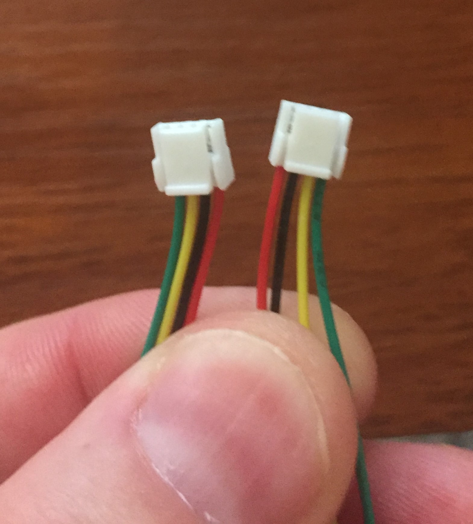
I rigged up a connector (using the white striping to orient the connections) so I could swap the power leads individually:
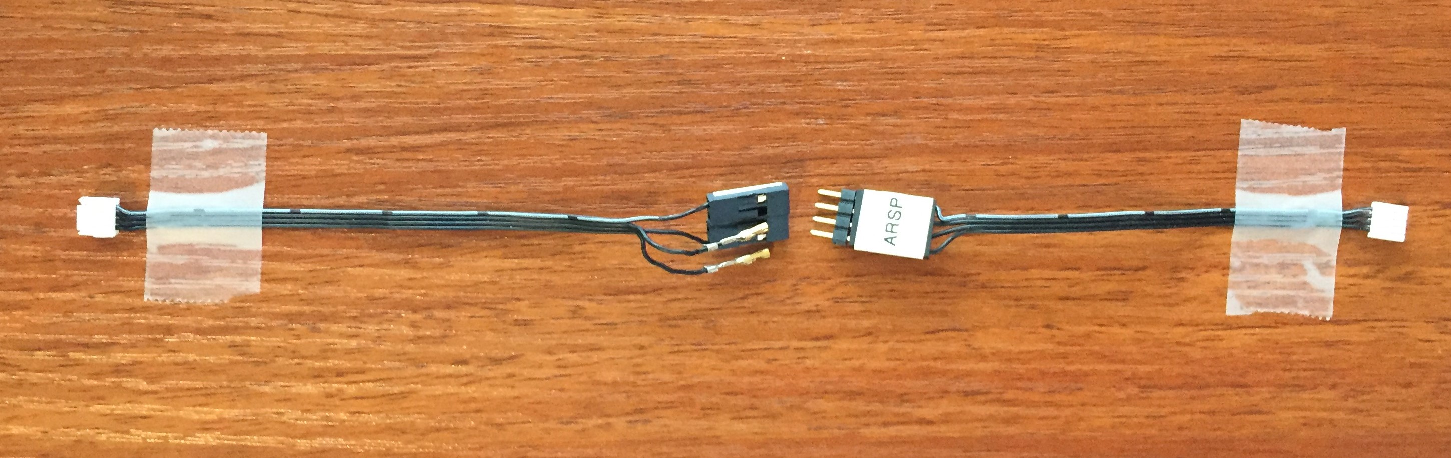
-
I noticed that the connectors are one “up” and on the other side they are one “down” which might explain the brownout issue as the connectors I bought are both one “up” on each side so when you plug that cable in the pinouts are reversed!
-
When hooked up the connectors to the bird as shown above no brownout occurs.
-
I then plugged in both the clock and data connectors to this setup and turned her on:
- No brownout occurred and the airspeed indicator on the HUD is a rock solid 0.0 which is the behavior I saw with my previous franken-VTOL aircraft.
I blew in it and IT WORKS!! YAY!!!
SO…
-
Now that it is reporting airspeed I did some further figuring, it turns out that you DO have to have this sensor completely hooked up before booting up the autopilot or it will not recognize the sensor. This fact played a part in the confusion I was having.
-
One connector up and one connector down was a detail I missed and explains a lot.
-
I now have to find a way to be able to plug in the battery and keep the sensor attached unless anyone knows of a way to make this work otherwise? I can’t see Foxtech or others not knowing about this issue.
-
I do remember reading about this problem but I don’t recall what kind of airspeed sensor they had.
-
Doing a pre-flight calibration does NOT make the sensor work if you did not have it plugged in on bootup.
-
Doing a Preflight Reboot Shutdown command DOES make the sensor work. I am not happy with using this option as it means I am adding another thing that can go wrong in the field and I am booting twice while having to connect the nose cone (which is more stuff that can go wrong and is not as good as having a permanent connection)
I put the airspeed sensor in the fuselage with long silicon tubes between it and the pitot tube on mine, now it is always connected even with the nosecone off, works great.
I know that the position of the airspeed tube is important, where did you attach yours? Got a pic?
The tube is in the same position, on the tip of the nose, just the sensor has moved to under the battery tray, I also did away with the PCB and connectors.
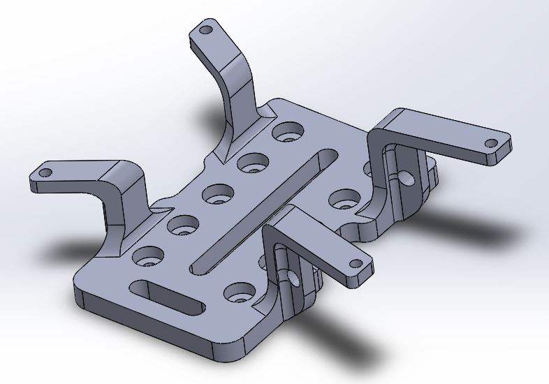
Here is my contribution, A mount for the Pixhawk 2.1. The holes on the bottom are for attaching spacers for the Mateksys FCHUB-6S power distribution board.
Nimbus 1800 AP Bracket v3.STL (522.0 KB)
1 Like
Thanks Greg: I checked Fox Tec put a ruler on a 17.5.5 inch prop they use for the rear motor wow that would almost hit the body and the V tail wouldn’t that cause prop wash vibrations to the plane? My motors 580 kv front and 400kv rear,I do have a spare 320 kv motor from one of my heavy lift X8 Octo’s I can use if it’s needed
So, instead of having the sensor and the tubes in the nose cone and running a wire between the nose cone and fuselage you have the two silicone tubes running between the nose cone and fuselage?
Yes, just the two tubes, they nice and flexible so tuck away in the nose cone when it’s on and don’t kink.