OK, so I’m having issues getting my PX4FLOW 1.3.1 working with my Kaukute F7 (non AIO), I’ve done the tutorials, flashed the hardware I needed to, and set everything I can think of. I2C. What am I missing that may (or may not) be obvious? I have a LIDAR LITE v3 running along side of it (also I2C). It seems to be running OK although I question the range readings.
First thing to check is power. I’d recommend an independent power supply for the flow and lidar: not tapping off the kakute 5v rail.
Just tried that. Clean power from separate 5v BEC, same result. I can connect directly to the PX4FLOW and get do the focus routine in Mission Planner. I get no opt_m_* output and the OPTFLOW BAD HEALTH warning. No I2C errors, and wiring is right. Perplexed.
did you see during reboot via mavproxy or terminal in the MP what is it actually found on the I2C bus and on what addresses?
first, i think, it was stated before that it does not work on address 42 - try 45, 47, 49.
try removing all other devices, only leave that unit alone. you can also try to do a custom hwdef for kakute - i think it was possible to find there a set of pins to make a second i2c bus work. but i do not recall if i made it work or not when i played with it.
I set the address to 0x49 using the soldering pads on back. Changed the FLOW_ADDR = 49. Still no joy. I’m at a loss on how to view the boot up parameters. CLI terminal in Mission Planner gives me gibberish and I’m trying to get up to speed with how to use it. Also, I took everything else off of the I2C bus - except the integrated BARO. I have two GPS’ (only one compass connected to I2C), the LIDAR LITE V3 and the PX4FLOW on I2C.
just got smart on MAVproxy (well, sort of). The LIDAR is being sensed at I2C address 0x62 as expected but the PXFLOW does not seem to ever get sensed.
I think part of my problem might be related to this
Apologies for the multiple posts but this is giving me fits. I’m convinced that the PX4FLOW is not coming up on the I2C bus. I recompiled the firmware with some pretty obnoxious debug statements in AP_OpticalFlow_PX4Flow.cpp. No joy. Compass, baro and LIDAR Lite all seem OK on I2C. Tried 2 different I2C splitters, cables, put the 'Flow on solo, changing the address to 0x43 (and 1 in the config), and I’m powering with independent BEC. I do get good data and video from the 'Flow when I connect directly to USB in Mission Planner so I’m fairly certain the board itself is in good shape.
Question for @Paul_Atkin1- Is there anyway to force an I2C probe for 'Flow in the hwdef.dat?
hwdef only makes sure you do have an I2C bus, it does not go to the level of devices you may have on it - hwdef defines the platform itself, not the peripherals…
what i did and you can do - dig into code and add more log statements into the i2c discovery module, there is additional debugging available there, i do not recall frankly what is in it but it is more or less straight forward. then during reboot look at your debug output.
also, with i2c it is very critical to have shortest possible wires. use shielded ones as well, if you can. and, remove all the rest from the bus during the experiments. it also helps if you have an external i2c bench board - on arduino or something else, just to check your sanity and make sure the unit is indeed alive.
Thanks @Paul_Atkin1. I’m having a tough time getting gcs().send_text to print out to either mavproxy console or the message box in Mission Planner. Tips or tricks?
Solved: In OpticalFlow.cpp, the “AP_OpticalFlow_PX4Flow::detect(*this)” was never being fired. One reason , I believe, was that the board type isn’t defined in the HWDEF.h. Also, the logic in lines 110-122 in OpticalFlow.cpp appears to be flawed.
Works great now! Now the tuning fun begins.
From what I gleaned from the hwdef, UART7 is Serial5, yes?
The Kakute F7 has a fairly comprehensive readme file.
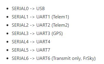
yes it is.
it is a link to my file, you can compare to the master - i do not think it was ever merged in.
i have there nodma added to serials and additional pwm(7) added.
serial 6 is not transmit only, it is a fully operational USART6.
uart7 by default is mapped to receive ESC telemetry, if you use 4in1 esc connector it will feed into RX of the uart7.
other important option - i did not test it completely.
the
USART3 (GPS)
PB11 USART3_RX USART3 NODMA
PB10 USART3_TX USART3 NODMA
combination is also possibel to be altered into the
“PB10:I2C2_SCL” : 4,
“PB11:I2C2_SDA” : 4,
to bring up secondary I2C bus. should work, hypothetically, but, i did not test it.
That’s interesting! 20 characters…
OK. I’m good now. I wasn’t seeing ESC telemetry working in 3.6.4 so I compiled my own from master. Now I have voltage and current. We now need to figure out how to get the buzzer working.
Buzzer is working fine in my build. It requires normal standard connection and a lipo connected.
An alternative method to make buzzer working from a usb power is done here –
the ‘fix’ hwdef was made to work with a partially damaged F7 controller where i have managed to burn down 1 usart. so i had to relocate rcin and some other things including buzzer.
so in this version you need to use a bigger buzzer unit that can buzz from the PWM voltage levels and in this case you connect buzzer in between pin PD12 and a ground. a usual way allows to use smaller lighter buzzer that is about of 5mm in diameter. or 7mm. bigger one is about of 12mm, i think.
Compare to a link with a previous hwdef I sent before – you will see a difference. In a usual standard hwdef you connect buzzer to +5v and a PD15 pin.
KakuteF7-AIO-V1 pinout.pdf (22.7 KB)
refer to this pinout chart.