I tried setting the BATT_MONITOR to 4 and although that does display the voltage on the HUD of MP its displaying zero volts. I have the battery connected to the B+ and GND of the 8 pin JST connector. Are there any other parameters to set ?.
I don’t have any BLHeli_32 ESCs but do plan on getting some.
I do have Wraith 32s, but the Mini version, with no shunt. And I’m way better with a hall sensor then with shunts… I’ve seen how precise a hall is and how horribly off shunt measurement is. I’ve had two landings in the past where there was no juice left for a final break of descent - even if R/C reported 1.000 mAh remaining - and I hit the ground at 2 m/s. That was before Mauch sensors.
Anyway, just paid customs taxes for the FC so hopefully come Monday evening I’ll have it on my desk. Not a big issue if I have to find the FMU pin and solder current sense directly to it. Paul, do you get Vbat reading from the B+ pad ?
I see there’s no UART5 pins. Is that the dedicated OSD port ?
hi, what controller are you talking about? F7 or F7 AIO? on latter i simply have BATT_MONITOR=4. did not have to do anything else or special to make it work.
on F7 I use ESC telemetry - all it needs is to set batt_monitor to 9 and make sure one of uarts receives esc telemetry to its RX pin.
F7 AIO options are below, works with the kakute F7 hwdef in the current 3.7dev master:
BATT_AMP_OFFSET 0
BATT_AMP_PERVLT 31.3
BATT_CAPACITY 1500
BATT_CRT_MAH 0
BATT_CRT_VOLT 14
BATT_CURR_PIN 12
BATT_FS_CRT_ACT 2
BATT_FS_LOW_ACT 2
BATT_FS_VOLTSRC 0
BATT_LOW_MAH 0
BATT_LOW_TIMER 10
BATT_LOW_VOLT 14.2
BATT_MONITOR 4
BATT_SERIAL_NUM -1
BATT_VOLT_MULT 10.95432
BATT_VOLT_PIN 13
BATT2_MONITOR 0
I set the BATT_VOLT_PIN to 13 and I now get voltage reading in MP. I also get a more accurate reading if I set BATT_MONITOR to 3 which is voltage only, set to 4 it was 1 volt lower than the actual battery voltage but 3 is fine as I have the non AIO F7 board which does not have a built in current monitor like the AIO. This is great as now I can setup the battery failsafe and alarms.
ok, with voltage not matching correctly - with 3 or with 4 - you need to use MP app, get to the section where you set battery monitor setting, use multi-meter on the battery while you are feeding model from it and literally type in an actual value in the first section in there - where you see the computed voltage value. after you hit ‘tab’ or ‘enter’ - MP will adjust the value of the batt_volt_mult parameter.
@Paul_Atkin1- those values work for both voltage and current. FWIW, I’m have an 8" quad operating the KF7 with dual GPS and a TFMini range finder. Latest .apj. I’m running Crossfire w/MAVLINK for both Telem and RC control. Finally, I have a HAZZAH ESP8266 for high speed, local wireless communication. “Long” range ground station connectivity is via Bluetooth direct form the Crossfire transmitter. Full version transmitter, set TX/RX to MAVLINK, BLUETOOTH to MAVLINK and RC Control via MAVLINK - On. Also if your RCVR is a XFIRE mini, TX/RX are defined on outputs 3&4 vice 1&2.
Big thing to note if anyone is reading this for a similar purpose - full ground station control is possible via the GS XFIRE trans Flight controller data path only when you are in RFMODE 2. RFMODE 1 reduces the available MAVLINK data packets substantially. As far as I can tell from limited flight test, RFMODE 1 only sends the basics, positon, altitude (?), heading, volts. I’m working with TBS on the full list.
I ran out of UARTS for my second GPS. I tried tapping UART7 (mapped to serial5) for the TxRx for the second GPS. Lo-and-behold it worked great Pull TX from the small pad next to the ESC JST connector and pull RX right off of PIN 7 on the back side of the JST. SERIAL5 set to GPS of course. No ESC telemetry but as mentioned I’m getting something using BATT_VOLT_PIN 13 and BATT_CURR_PIN 12. Voltage is solid but I think I need to calibrate the current readings.
For the super curious - google ARDUPILOT KAKUTE F7 HWDEF.dat and you can see exactly how the internal pin mapping is done through ChibIOS.
For the folks who have this flying - did anyone note a swapped pitch commands. Up is Down / Down is Up in pitch. Roll and Yaw being correct? I suspected motor numbering but I compared BETAFLIGHT pin maps to ARDUPILOT and they seemed correct.
Also - has anyone successfully got BLHELI pass through to work?
What range do you get in mode 2? Mine switches to mode 1 w/in 100 meters. TBS is telling me I should get several kilometers. however, everything they’ve had me try has made no difference, and they refuse to admit my transmitter has a problem and RMA it! I’m getting quite frustrated w/ them.
Either mine is performing as expected, so no one is getting more than 100 meters in mode 2. Or my unit is defective. which is it??? TBS is running me in circles… I’ve had an open ticket w/ them since JUNE!!
it has to be noted that kakute f7 hwdef file was made for the F7 AIO initially, and motor order in the hwdef reflects actual location of the AIO F7 FC corners if board is oriented correctly, its nose forward, orientation 0.
if somebody uses F7 FC with an external 4in1 ESC - then all this motor order gets whacked and there are 2 options - either to redo hwdef file and recompile code - that i am doing always, or pull pins out from a connector and realign.
now, if motor order is screwed - it will not be probably pitch reversed, unless you got lucky. most likely copter will flip immediately upon takeoff. reversed pitch is usually a radio link issue, but, not sure which one you got.
i bet what you got is the old betaflight model in the taranis got used now for the ardupilot - it is not same mapping wise. it is possible to make it same, but out of the box they differ - i remember that as when i tried to flash betaflight first time into a model that has arducopter it also flipped around in a wrong way with controls not matching - channels assignments in the taranis were not matching.
blheli passthrough works fine on all my models - from master, on kakute and nanov6. no issues at all, you can easy check if you set battery monitor to parameter 9 to get it from ESC first - to see if telemetry is going in.
which module you refer to - r9 mm? i did not ry mine yet, to be frank, my r-xsr works up to a mile it seems, and i did not fly any further lately.
i still plan to do a slave mode r9 mm integration in daisy chain post r-xsr but did not get to it yet. hope it is possible.
That question was for Mark about the crossfire.
Mode 2 does full bidirectional telemetry like a traditional telemetry modem. But that only works for me up to about 100 meters. TBS is saying that should be working up to about a mile. But at the same time is telling me there is nothing wrong w/ my equipment.
Mode 1 does unidirectional telemetry like frsky or anything else, and I’ve never reached the limits of that… I’ve been out about 3 miles on that.
I just need more range on full bidirectional telemetry. well, what I need is for TBS to either admit mode 2 is extremely limited, or to admit my transmitter has a problem and RMA it… It can’t be both, which is what they are trying to tell me.
is crossfire better than that R9 set of receivers? if i understood correctly - R9 will have telemetry up to its full range and it has quite insane transmit power.
@Paul_Atkin1 wicked1 is talking about full bi-di telemetry, where you have your laptop connected via BT to the Remote Control and takling MavLink to the FC using the RC comms, without a second pair of SiK radio modems involved. Frsky can do this @9600 baud. There’s a pair of serial S-port modules for that. But 9600 is too slow for our purposes, so I haven’t seen anyone trying it. TBS upped the ante and does 57600 in that Mode2 they are talking about.
I don’t own any TBS hardware, so I can’t tell if the RC can tap that high-speed MavLink stream, so it can display telemetry info on its screen, or you are left with watching only your laptop screen for info. I suspect the latter
You can use the same scripts to show telemetry on the radio. I personally don’t care about that… I’m either in my goggles or have my laptop/tablet. I just need bi-directional telemetry so I can change mission parameters, etc, while I’m way off on a long range flight.
Crossfire would be an ideal solution, if it actually worked.
@wicked1. Like you, I am getting about 100 yards or so on MODE 2. I attribute it to the operating environment I’m in, but who knows. Voodoo. I’m talking to TBS about it now but don’t hold out any hope. I’d be very interested to know if the R9 can do bi-directional MAVLINK TM throughout the entire range. Short money for the units and gets us where we’re going. I have not tested the range on the ESP8266 connection. It would be funny if the $12.99 board does 3x the distance of crossfire on MODE 2.
@Paul_Atkin1, I think I got lucky. I was smart enough (barely) to check/fix the channel mapping before pulling power in anger. The craft flew fine with pitch reversed, just had to compensate quickly. Didn’t like that so much so I tried just reversing the input on the TARANIS side. Bench test was good, flying it tomorrow. Also - would it be too much trouble for you to drop a quick primer here on the tool chain required to recompile .apjs form HWDEF.dats? Linux if you please. If not- a good link would be helpful too. I have not found a good source for that.
@Mark_Ward ArduCopter has always been pitch-reversed. It’s the first thing I do when setting up a new RC.
About bi-di MavLink, FrSky will do it, full range, at 9600 baud, via a pair of SP2UART modules. But 9600 is way too slow for arducopter environment.
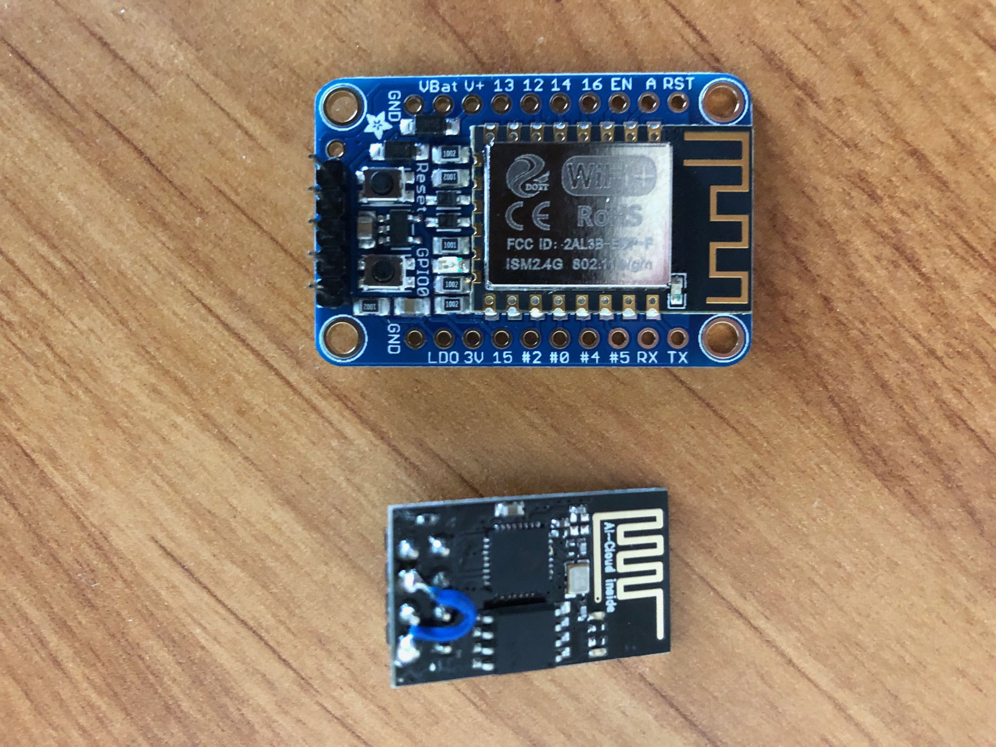
usual cheapest esp8266 on my model did close to 80m or so. but not more than 100m for sure.
it is the one with no proper antenna -
there are more of them with better antennas. i did read somethere that with an antenna it can go almost to 500m - and google helped.
try it, those are in my opinion by far superior methods to any old modules.
as of setting the environment for compilation - i simply grabbed latest ubuntu image from their site and rolled up a virtual machine on vmware workstation i use. ubuntu 18.04.1.lts.
then i think i simply followed development wiki to setup the rest. it did not take long.
i use eclipse to sync with github, made a fork of ardupilot project into my account -
you then go into the folder where all hwdefs are -
~/git/ardupilot/libraries/AP_HAL_ChibiOS/hwdef
copy what you need into your own directory, like, a ‘gecko4’, alter what you need, then use ‘waf’ command to setup compilation:
paul@ubuntu:~/git/ardupilot$ ./waf configure --board gecko4
then build it:
paul@ubuntu:~/git/ardupilot$ ./waf copter
overall, just hover around that ‘building code’ root page and ask here for questions if you will get any.
on windows i could not setup it to build anything usable, it was giving idiotic errors on odd places during compilation, but on ubuntu everything worked with minimal effort and produces correct builds.
i sync my fork on the arducopter github web page, then go to my eclipse on ubuntu, pull it from my fork into it and build from there. it works well for me this way.
@ThePara - on the pitch reversal - Well there you go! Seems I stumbled on the right answer. Just finished round one of flight test and could not be more pleased. Position hold was rock solid right off the shelf. Much better performance than with iNAV after days of tweaking. My ground station is linux based (tinkerboard). Integrated video, power and the like. This means I’m limited to APM PLANNER2. Tried MP using mono but the chipset on the tinkerboard is rubbish. QGC is simply out of reach,
Yea, that’s about right. I have several of the cheap ones and one with the breakout board (5V compatible) and it’s range is definitely better. But not enough to make any difference if it’s being used primarily for configuration purposes which is what I use them for also.