Hi,
I hope someone can provide some kind of solution on how to hook up the Here+ RTK Rover to Usb without having the usb cable coming with the Here+ RTK Base.
I only bought the Rover module due to having some other base station in use and now i lack the ability to update the Rover Firmware.
Hope someone has a solution for this because i wasn’t able to find the cable somewhere to buy
1 Like
@proficnc Any advice? Right now, I’m looking at making my own FTDI USB cable by sacrificing one of the cables that came with the Rover. It’d be great if the cable was sold separately and bundled with future Rovers. I already have a base RTK that’s a different brand plus people could use the networked solutions as that requires no unique local base.
I also faced this issue. My vendor SpektreWorks took care of me and wired me up a USB cable. I also received them from 3DXR, so maybe you could reach out to them.
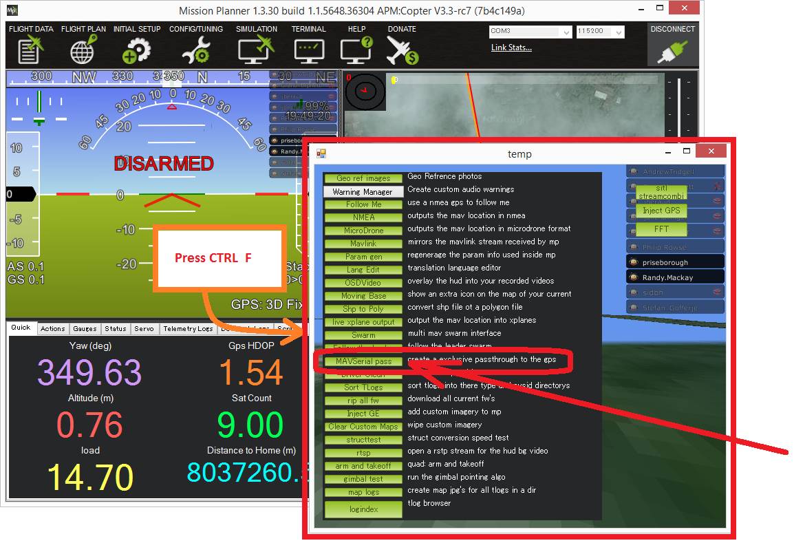
@Niels You can at least get access to the Rover configuration and status over USB by using the Mission Planner’s GPS proxy capability documented here:
http://ardupilot.org/copter/docs/common-ublox-gps.html
http://ardupilot.org/copter/_images/GPS_PassThrough_MP.jpg
I tried to upgrade the firmware through that approach, but it failed. It looks like u-center is expecting a serial connection for firmware updates.
Send an email to 3dxr because that was the place i ordered the rover module from. Let’s wait and see… Maybe a pinout of the usb port would be enough but can’t find one
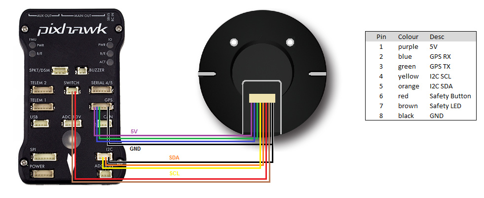
I saw this posted, but somebody said there was an error in the wiring. I think there is an error since the Here+ compass does not get registered on my Pixhawk:
This an the email I received from a few months ago…
"…If you open up the HERE+ puck you will see two connectors, the large one that goes to the autopilot, and a smaller one for the USB cable.
The individual pads of the USB connector are labeled, so you should be able to get the pinout that way. USB requires 4 connections, 5V, Ground, D+, and D-. If you are cutting up a USB cable, generally 5V is Red, GND is Black, D+ is White, and D- is Green.
Pin 1 on a JST-GH Connector is on the left When you hold the connector such that the locking connector is facing up (It is red on the cables that come with the Pixhawk 2)
The pinout is the following:
+5V
D+
D-
GND
Shield (Optional)
Good Luck!"
I never ended up getting my own wiring to work, but when they supplied me with a cable, it worked great thanks to @David_SpektreWorks.
1 Like
The wiring to the pixhawk uses a completely different connector and port than the USB for updating the chip
.
The connector inside is not labeled, at least not in my unit.
Reached out to 3dxr and they offered to send a cable. Will wait and see when that one arrives.
Thanks guys
If we created a cable for the main port of the GPS from the GPS 1 cable that was connected the RX, TX, ground and power to an FTDI cable, should that work to upgrade the firmware?
No; the connector on the GPS board that you need to use is not the main large connector. It is an auxiliary port hidden inside the case of the HERE+. You need to remove the board from the case to update the firmware.
I just assumed the other plug was +5V, Ground, D+ (RX or TX?) and D- (RX or TX?) as well based on your description of the cable above. Does the second connector need to use an FTDI cable then or will a generic USB cable work?
OK, my assumptions are probably wrong about the connections. I just assumed they were the same, but now I realize that they different. It’d been nice if the auxiliary port was a micro-usb instead since it appears to really just be a USB port.
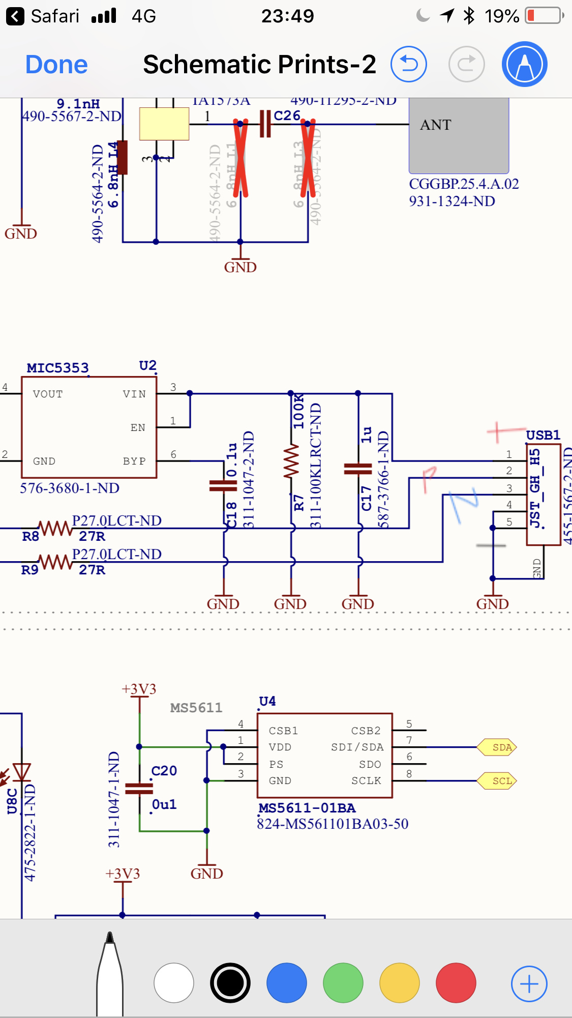
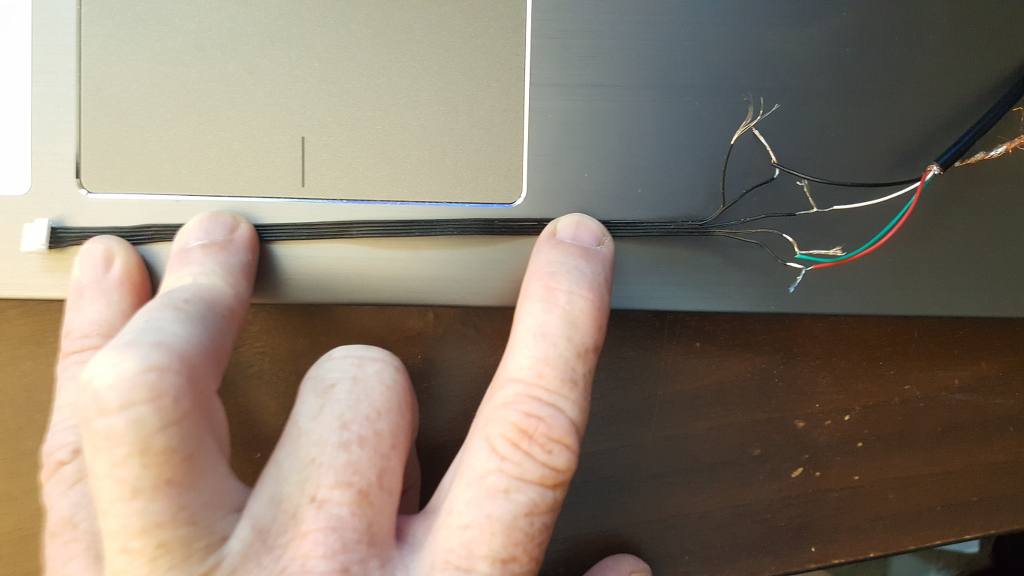
This is what my port looks like:
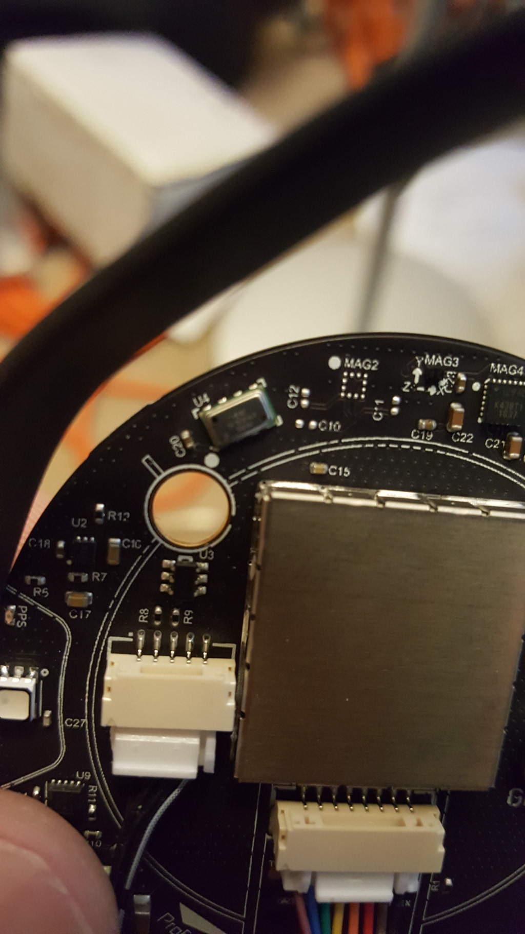
I’m assuming the pin to the right of R8 is D+ and to the left of R9 is D-? based on your explanation above.
USB pinouts
http://www.hobbytronics.co.uk/usb-connector-pinout
@Naterater, would you take a picture of your cable or diagram how the cable is wired? Does your USB cable power the GPS as well or do you have to power it with the cable from the Pixhawk? (The instructions for firmware update mentioned having to power it with the Pixhawk.) I tried wiring it, but I’m not getting power and it doesn’t show up as a COM port even if I power it using the Pixhawk. Either my wiring is wrong or I need to use the FTDI cable. @David_SpektreWorks? @proficnc?
Hi Rob
The plug is standard USB, but no power.
The recommended method of upgrade is the Serial pass through with mission planner.
@proficnc I had tried doing the upgrade with the u-center and the GPS pass through with Mission Planner, but it failed. I’ll try again.
Is this comment correct?
"I’m assuming the pin to the right of R8 is D+ and to the left of R9 is D-?"
in this posting:
https://discuss.ardupilot.org/t/here-rtk-usb-connection/29826/13
@proficnc I hooked up the USB green wire to 2 and white wire to 3, but the USB device does not show up. (I didn’t connect ground and power since its being powered by the Pixhawk connection.) Should that work?
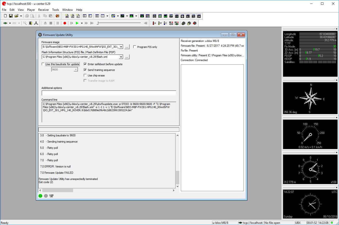
FYI, this is the error I get when I attempt to upgrade the firmware using the Serial Port GPS passthrough:
0.0 Updating Firmware ‘E:\Software\NEO-M8P-FW301-HPG140_RNwithFW\DO_EXT_301_HPG_140_ROVER.91bbd17d889e0fe40c2d823991595224.bin’ of receiver over 'STDIO’
0.0 - Opening and buffering image file
0.1 - Verifying image
0.1 Image (file size 502984) for u-blox8 accepted
0.1 Image Ver '3.01 (db0c89)'
0.1 - CRC= 0x90A98096 0xFDD8261E
0.1 - Trying to open port STDIO
0.1 - Setting baudrate to 9600
0.3 - Sending training sequence
0.7 - Received Version information
0.7 - Receiver currently running SW ‘EXT CORE 3.01 (d080e3)’
0.7 - Receiver HW ‘00080000’, Generation 8.0
0.7 - Sending ROM CRC-Mix-Read
2.0 ROM CRC: 0xA15AF099
2.0 u-blox8 ROM2.01 hardware detected (0xA15AF099)
2.0 Getting Port connection to receiver
2.3 - Connected port is: UART1
2.3 Commanding Safeboot
2.8 - Re-enumerating…
3.8 - Setting baudrate to 9600
4.1 - Sending training sequence
5.1 - Retry poll
6.1 - Retry poll
7.1 - Retry poll
7.1 ERROR: Version is null
7.1 Firmware Update FAILED
Firmware Update Utility has unexpectedly terminated
Exit code (2)
@proficnc What are the recommended settings for the firmware update when using the Mission Planner pass through:
I got my USB cable working finally. I just cut apart a regular USB cable and wired it to the serial cable using this setup. (I had to cut down a 6 pin cable to a 5 pin since I didn’t have any 5 pin cables.) I thought I had installed the VCP driver for the u-blox GPS already, but I hadn’t. The GPS showed up in the device list as soon as I installed the driver. Thanks to @proficnc and @Naterater for the help!
(I still had to power the GPS using the connection to the PIxhawk BTW.)
2 Likes