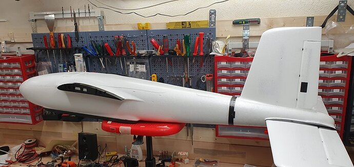
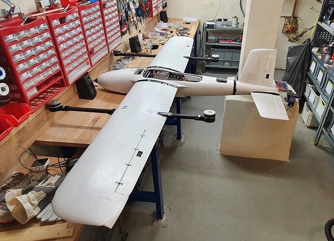
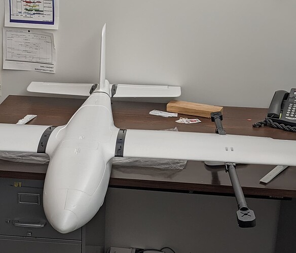
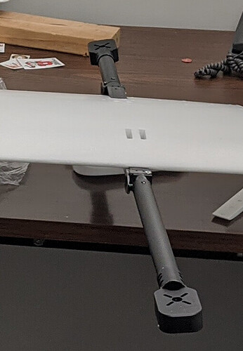
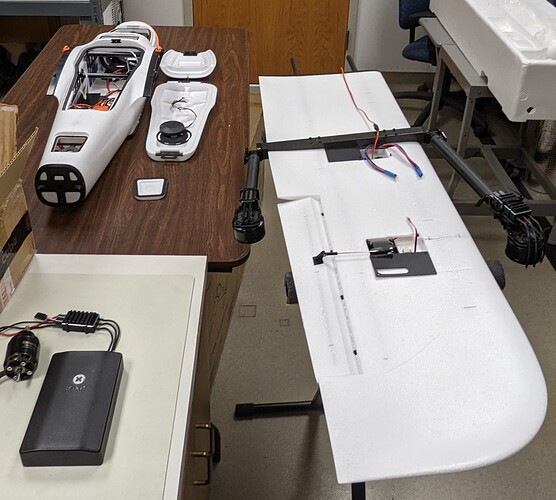
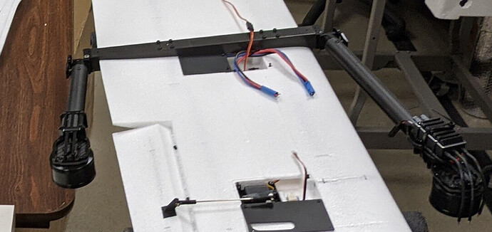
After a delay of nine months I could finally start building the MFE Fighter. For more than half a year I had no real workshop, because my basement was flooded last year by the flood in Central Europe. I was lucky that it only hit the basement. At the turn of the year the basement was renovated and in February I could start to rebuild the small workshop with a bigger and better workbench from scratch.
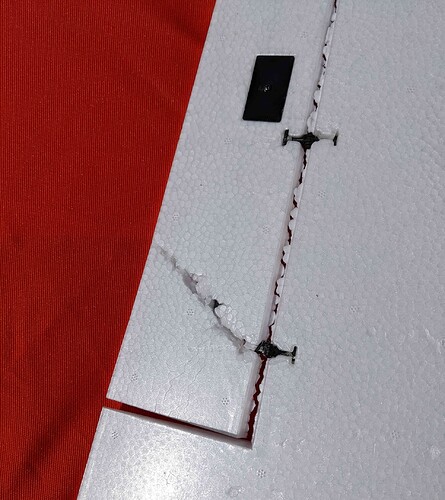
A few days ago I finally started to build the MFE Fighter: When unpacking (shipping by Banggood last year within Europe) unfortunately again (as I often had to experience with Banggood) damage appeared. Two broken rudders are excusable, but dog-ears at the vortex inducing wing tips are an absolute nuisance, because they can hardly be bent back to the way they were, even under hot water. Of course, MFE can’t do anything about that. In any case, I will no longer buy higher-quality aircraft from Banggood.
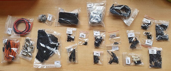
MFE itself has packaged the fighter very well. After unpacking it took a while to get an overview of the many smaller EPO parts , well labeled baggies,
plastic parts and the wooden parts. As
@GregCovey already mentioned, the assembly videos (link
https://www.youtube.com/channel/UCeg2HzMdPA3C3PPG3yEycQg/videos ) in conjunction with the parts list illustrations (
Index of /Fighter/ ) helps to know what is what.
As with others, my package also did not contain the glue. I took UHU-Por because I have used it to glue all foam airplanes together so far. (But you should have experience with UHU-Por. If you let UHU-Por dry and then press it together, it holds immediately and very well (depending on the pressure, not on the pressing duration), but you can’t correct a millimeter more if the positioning is not correct. So you have to join most parts while the glue is still viscous and press again a few times after a few minutes.)
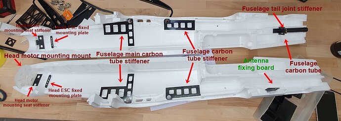
When assembling the left and right fuselage, a second person is very helpful. Before joining, I glued in the following parts (as named in the manual):
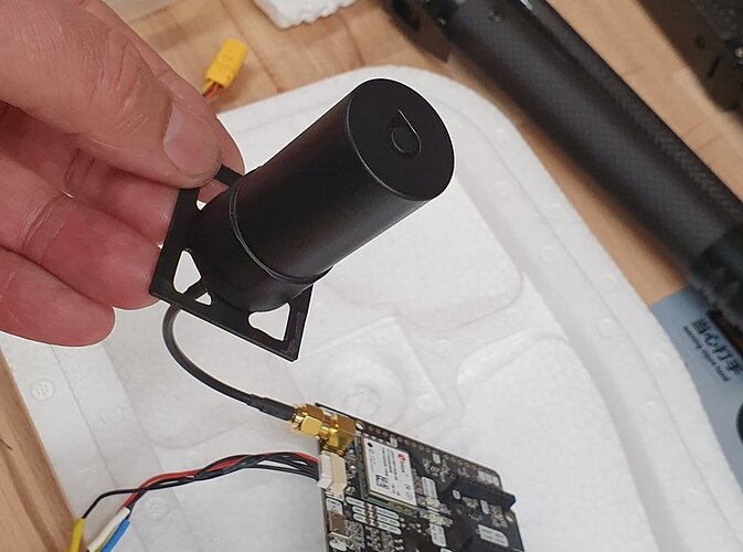
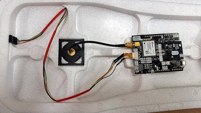
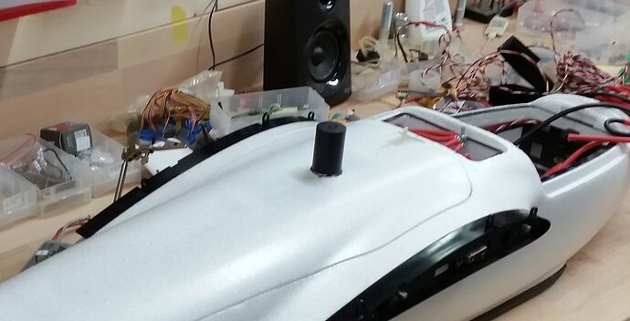
All other parts (including „GPS locating board“) can or must be glued in place after both halves are joined together. Only the „antenna fixing board“ is optional. There are two of these antenna mounts included, which can be installed in different places. Perhaps I will install the external multiband L1/L2/L5 helical GNSS antenna with a weight below 18 grams there
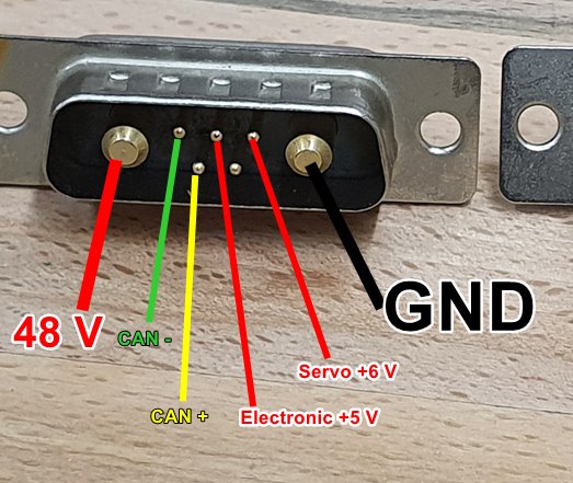
In the last few days, I finished the fuselage and tail, as well as soldered the tail wires to the Sub-D connectors and installed the rudder and elevator servos.
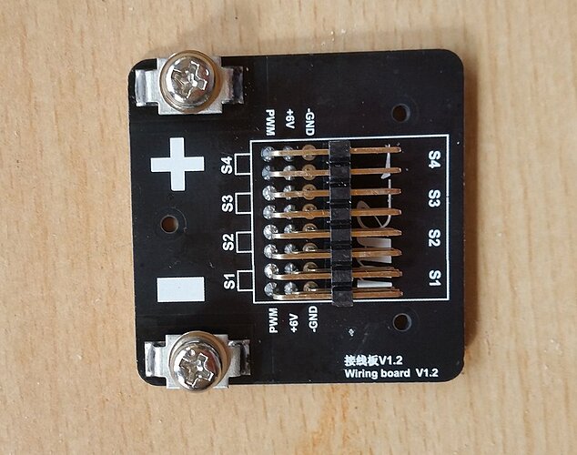
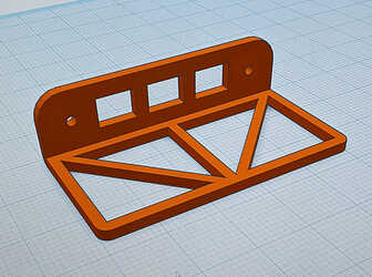
When building the wings, it was disappointing that the “Wing Wiring Boards” are not included in the package.
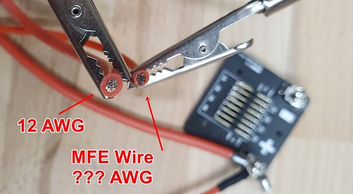
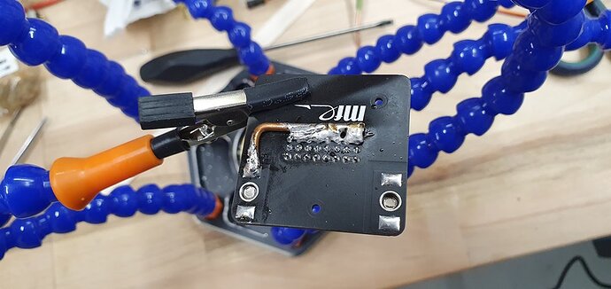
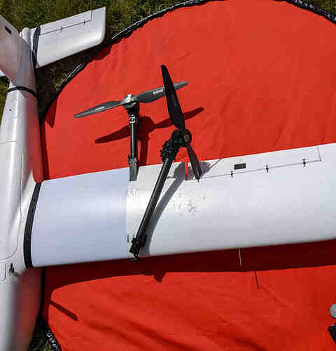
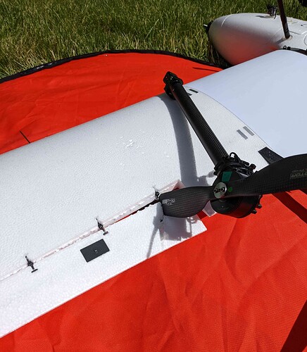
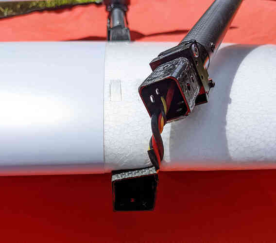
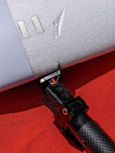
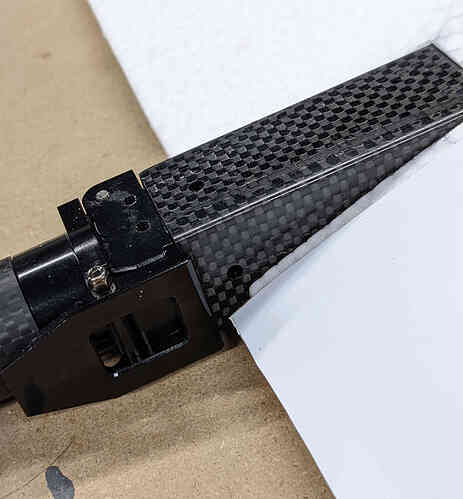
I have purchased the plate separately, because I want to keep the quad parts dismountable. But I will take stronger high current cables to the connectors on the wing roots than the ones included.
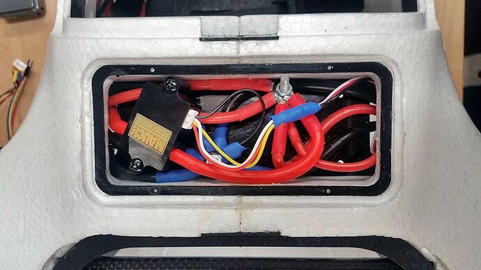
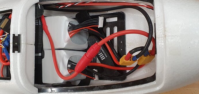
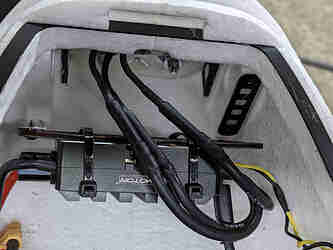
In the fuselage, 10 AWG is provided for the power cable because I don’t want any losses during hovering for heating cables that are too thin.
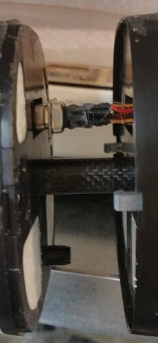
I haven’t soldered the Sub-D connectors to the wings yet because the connectors are very hard to pull and I’m worried about damaging the wing or fuselage when pulling them apart.What experience do you have with it ? Is there a trick with which at least the connections can be made smoother ? I doubt also that these SUB-D connectors will survive many plugging cycles.
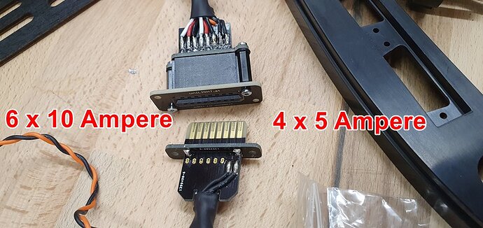
For testing I ordered a special model plug from the company Unilight (
uniLIGHT.at - Floating DIRECT ), which can be separated much better and was developed specifically for model aircraft. The plug in the picture has 6 contacts with 10 amps and 4 contacts with 5 amps load capacity.
Assuming the data here in the thread, the float current at 12s is about 50 amps. Would be 25 amps on each side. Two times three contacts of 10 amps each connected together might be enough and two plugs would easily fit. I’m not sure yet which plugs I’ll end up using.
Rolf
