The airspeed parameters depend on the sensor used, the pitot tube used and the installation location on the aircraft, but hardly on the aircraft type.
There are different methods for calibration: Calibrating an Airspeed Sensor — Plane documentation
I personally prefer the manual calibration.
1 Like
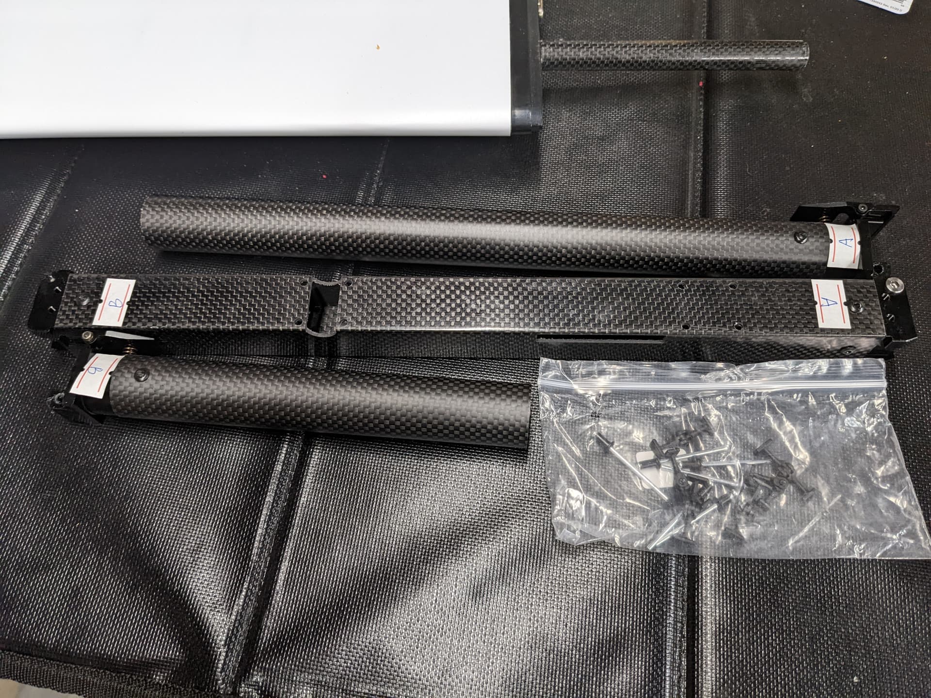
While waiting for a solution/fix response (MFE has graciously shipped a new left wing motor arm arriving any day now) I designed some reinforcement prototypes for the hinge junction of the motor arms. The original prototype was a 1 inch (25.4 mm) square tube which I decided to modify and add a bottom flange in order to reach the bolts that mount the motor arm to the wing. The flange helps a little with strength though it is more of a retaining feature.
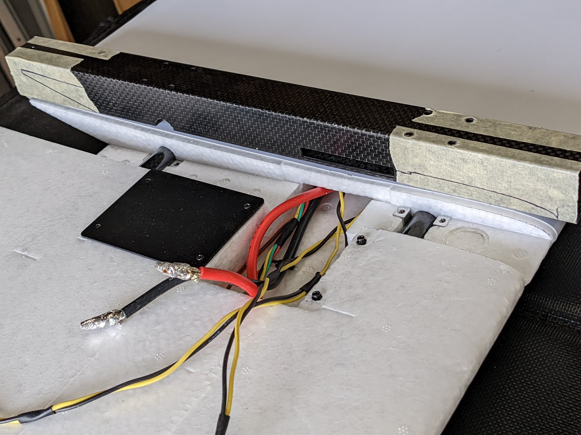
Photo 1: wing profile traces on carbon fiber motor arms.

Photo 2: v2 3D model.
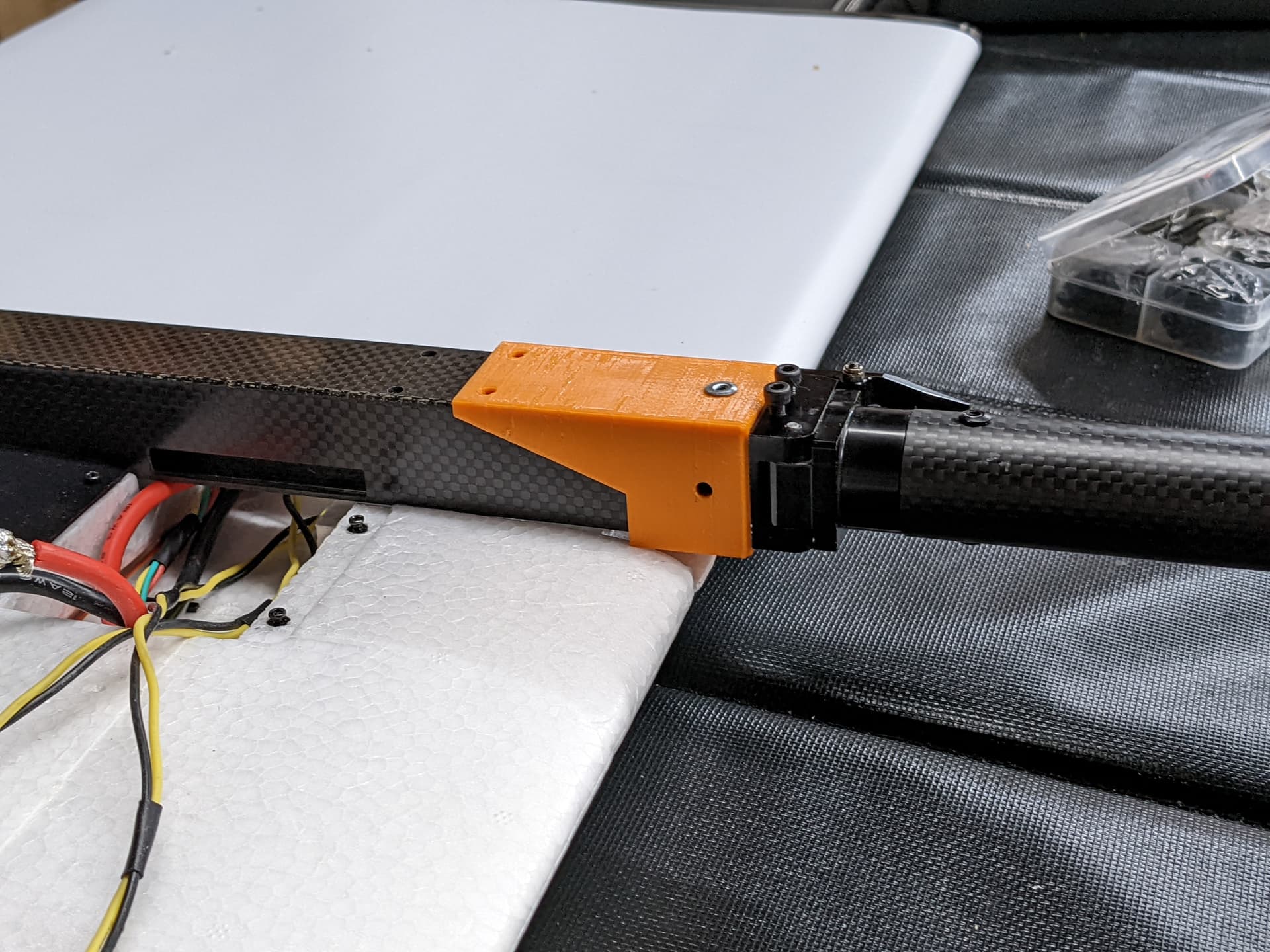
Photo 3: v2 prototype test fit.
The v2 prototype held strong with only 2 rivets; In fact, it was stronger/more stable than the other (stock) motor arm on the right wing with 4 rivets and glue.
My latest version (v3) has a top/bottom flange on the hinge side allowing you to fasten to the hinge with M3 bolts. The flanges are not required but I thought that it added some peace of mind if the rivets/glue fail or loosen so at a minimum you’d keep your motors in place, albeit wobbly.
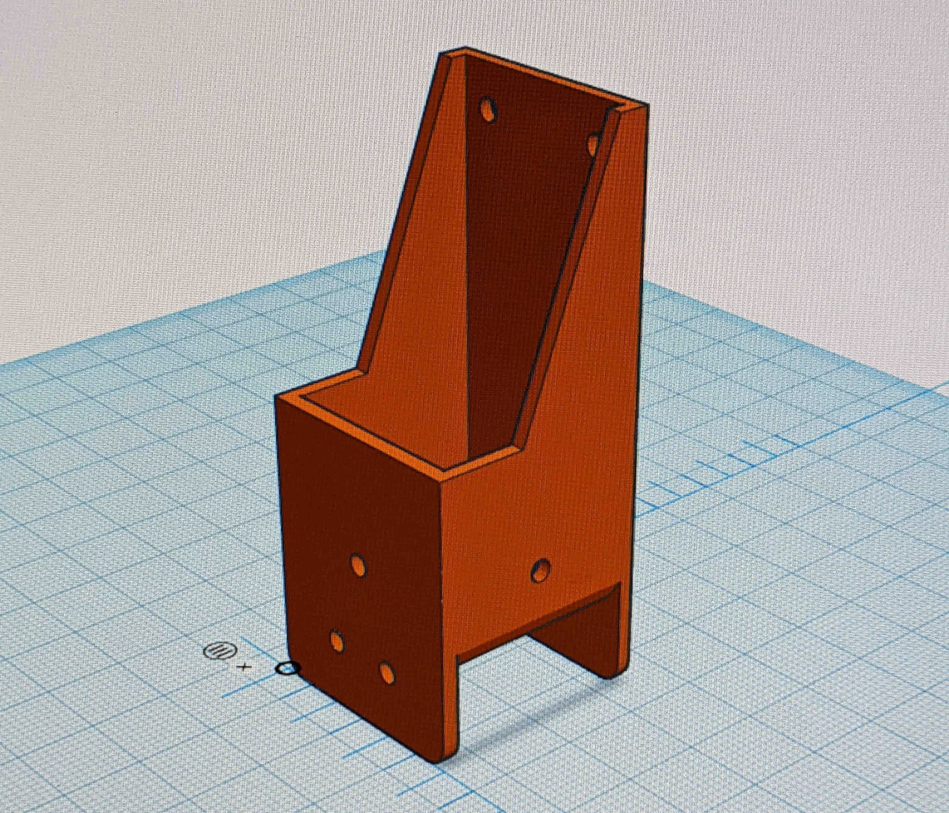
Photo 4: v3 3D model.
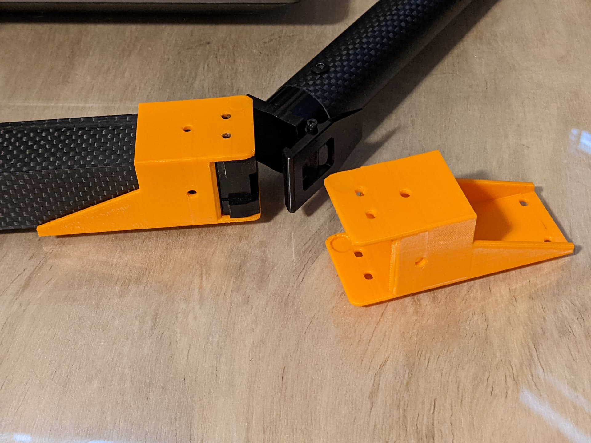
Photo 5: v3 prototype test fit. Weight is 10 g each for front motors.
The part design is blocky (quick job) and could use some curves/rounded edges all around as well as some layer tapering/thinning in areas less critical for strength. Aside from improvement on aesthetics, it should get the job done. The walls are 1.8 mm thick (2 mm originally, added 0.4 mm clearance for the CF tube after test fit) and the outer dimension is 29.4 mm. I made it out of PETG for UV resistance and strength.
Note: I’ve added the motor arms/hinges to the top of my preflight checklist in BOLD font.
Cheers,
Christian
2 Likes
@ton999 this is where I’m at with a reinforcement piece. MFE has sent a new left wing motor arm but my right wing motor arm has a little bit of wobble at the hinges. Perhaps new rivets and glue would be enough though I am leaning toward reinforcing with my 3D printed design.
Cheers,
Christian
2 Likes
Replacement parts for the left wing arm have arrived including rivets needed for the right wing arm and a handful of aileron hinges to replace the damaged ones.
Thank you for the fast resolution @makeflyeasy !
-Christian
1 Like
An appropriate solution from @makeflyeasy , admirable.
I got further with the soldering: On the flight controller deck, the H743 is mounted transversely so that the SD card port is easily accessible.
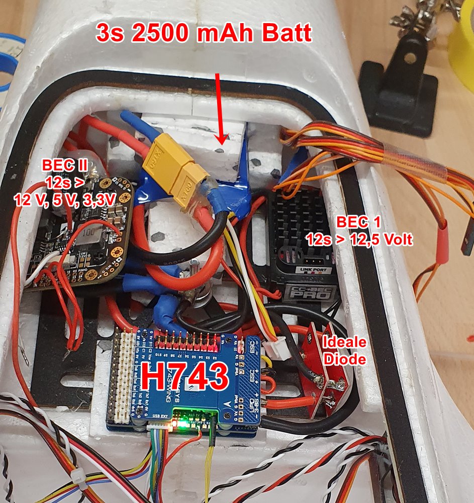
Behind it is a battery compartment for a backup battery (3s 2500 mAh). To the right and left are two 12s (4.2 V times 12 = 50.4 V) capable BECs and two ideal diodes.
Unfortunately the H743 can’t handle 12s, so it hangs behind the ideal diode on a 12s-> 12,5 Volt 10 Amp BEC from Castlecreation. If this should fails or the main battery fails, the supply of the FC, the servos and important electronics takes place over the second ideal diode by the emergency battery. Also, this battery is very helpful when making adjustments to the electronics on the ground, you can make the electronics settings without fear of accidentally starting the engines.
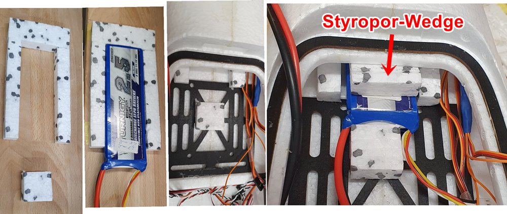
This battery is wedged in a holder cut from styrofoam fixed with hot glue behind the FC deck.
A UBlox M8N GPS including compass installed in the back of the GPS bay is connected to the FC conventionally (crossed serial + I2C)
To the front “small bay” the CAN-BUS leads to a Matek L431 node. Connected to it is the RTK-GPS, which is located in the lid of the cargo hold, as well as
the sensors of the Mauch current and voltage sensor. Later I would like to connect the ESC for the front motor here, but I want to wait before, how stable the CANBUS and the module really is. The same applies to the wings.
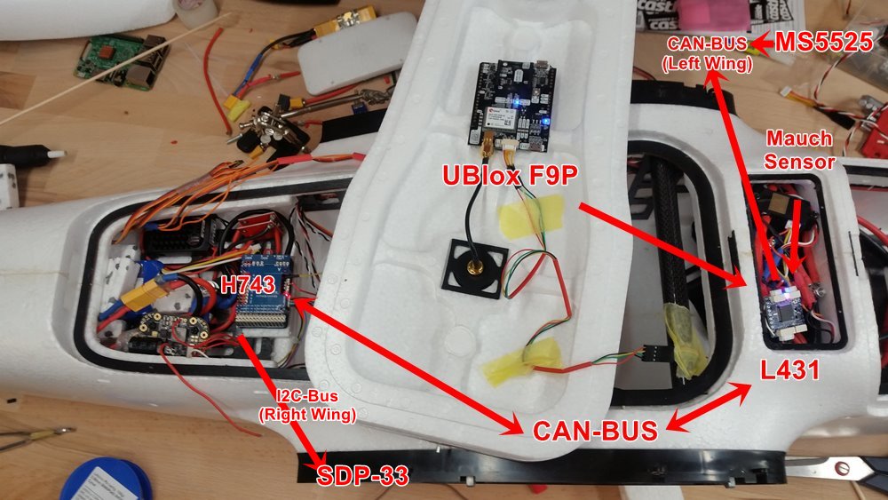
The CAN bus then continues into the left wing, where an 103-node has an airspeed sensor connected.
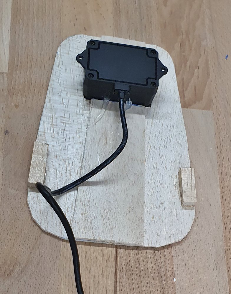
The I2C bus currently leads to the SDP-33 airspeed sensor in the right wing. Since I fly almost at sea level and do not have to climb high in the lowlands, I am still very satisfied with the SDP-33, because it does not need zero calibration before takeoff.
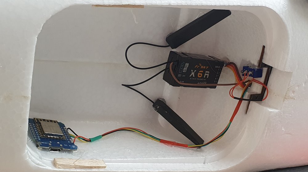
Since I don’t need to use a parachute, I’ve planned the bay for a lidar altitude sensor for now, plus an ESP-8266 WiFi device intended only for telemetry on the ground and the RX , currently still a simple Frsky including passthrough telemetry installed.
The only electronics missing are the LTE module and a Raspberry Pi, which will be installed in the front.
The powering up and first parameterization worked. The CAN bus with the L431 node is impressive. Right off the bat, the F9P GPS works just as the RTK correction signals are passed through.
Unfortunately, my time as a hobbyist is short, so the way is the goal. A few small things still need to be done, then it can go to the first hover flight.
Rolf
4 Likes
Hi Rolf,
First, I love the level of detail you’re providing in your descriptions and photos, thanks so much.
I believe I have the same Matek 12S PDB and Mauch power module that you have.
I’m a complete newbie to this level of DIY drone so forgive my ignorance, but how are you distributing the power to the ESCs? Are you using your Matek PDB for that or do you have a solution that you created?
Is the Mauch module just for current sensing?
Also, do you have a pin on the H743 you are using for voltage sensing?
Thanks again for letting us see your setup and process.
1 Like
I second these thanks.
Thanks to everyone here for sharing their knowledge. It sure makes building my MFE Fighter easier by seeing how you all do it.
2 Likes
Hi @Christian_H
Do you epoxy glue? Please make sure they are really strongly fixed… I found some time epoxy is not suitable if the surface is smooth… Good luck…
2 Likes
And at a minimum you can learn from others’ failures without the pain. haha
2 Likes
Thanks.
I did discover that the adhesive on the stock parts didn’t bond well to the coated aluminum (I peeled/scraped it off easily) and I don’t think it bonded at all to the carbon fiber. I tested some epoxy on one of my damaged parts and found that JB Weld plastic bonder held pretty good. I’ve reassembled the motor arms with epoxy, 3D printed reinforcements, and rivets. I’ll share photos in an updated post.
-Christian
1 Like
Disregard, looking at your pictures and diagram I see how it’s working. Thanks!
Sorry Grahem for taking so long to reply.
No, the Matek 12s PDB is only used to have another 12 volt, 5 volt and 3.3 volt source for peripheral power consumers.
The current distribution is done as on the Wiring Board with ring cable lugs.
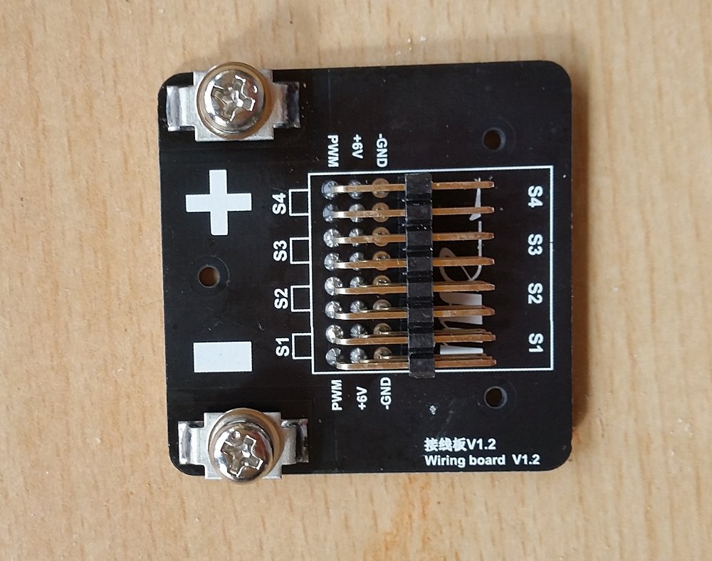
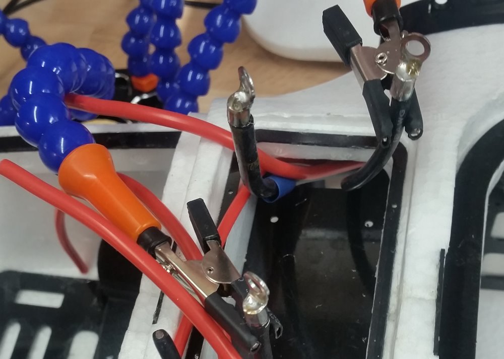
Soldering the ring cable lugs is relatively easy. You simply put the ring on the stripped end of the cable and let solder run in from above up to the edge.
The rings are mounted on M3 bolts with self-locking nuts.
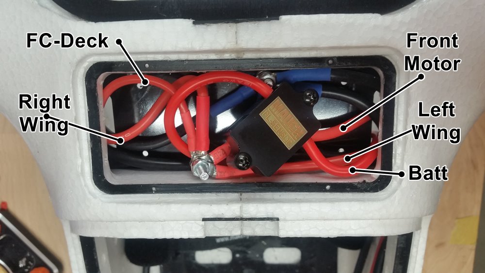
Both distributions (GND and +50V), the Mauch sensor and another Matek L431 CAN node fit into the front deck. Against vibrations I secured the cables and the L431 at different places with some hot glue.
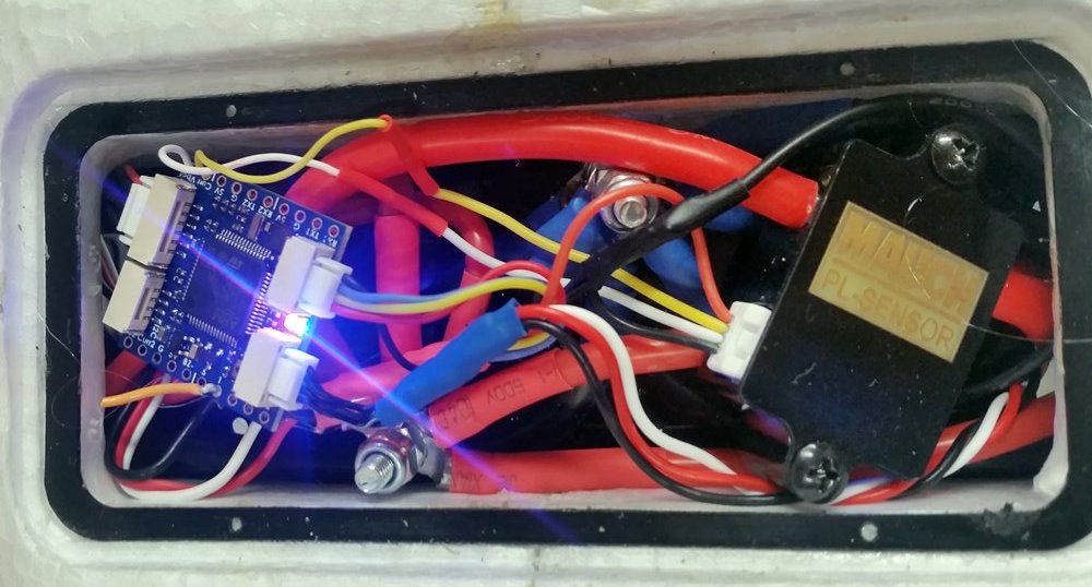
The Mauch sensor and a GPS are connected to the L431. The CAN bus continues into the left wing to an F103 with airspeed sensor. When hovering for the first times, the L431 is not at all noticeably upset by the power cables running past it. The log data looks flawless.
3 Likes
what about the flight duration
Before the first transition (I am still in the process of setting hovering parameters) I would be very interested to know what value you have chosen for ARSPD_FBW_MIN ?
The MFE parameters are unfortunately silent about this parameter. http://fw.makeflyeasy.com/Frame_params/Fighter_VTOL.param
Of course it is important as transition speed. The stall speed is specified with 10 m/s. The recommended cruise speed is given with 17-20 m/s. To me 10 m/s as stall speed seems optimistically low with 10 kg and 72 dm² wingarea.
With which value for ARSPD_FBW_MIN and which take-off weight do you fly ?
Regards Rolf
1 Like
After the first hover flights, I am very satisfied in more ways than one:
-
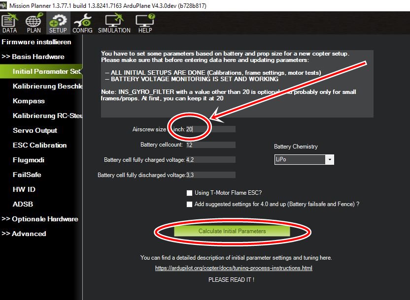
the MFE hovered with only slight changes to the P-values with Arduplane almost like “out of the box”. However, it is important to enter the size of the props in the Missionplanner beforehand and to let the MP make its changes.
-
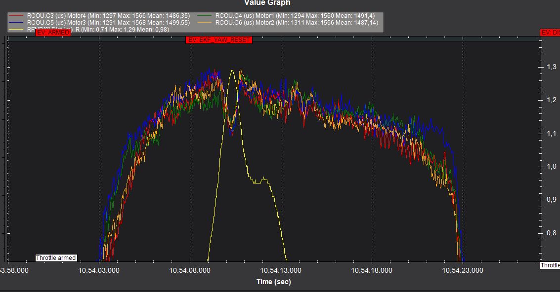
the motors run at hovering in something equal at 55 Ampere, 12s, 9,8 kg.
-
qhover works right away after a short QStabilize.
-
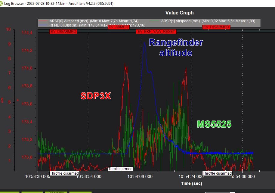
as expected, the interference with the pitot tubes or airspeed measurement only occurs in the ground effect
-
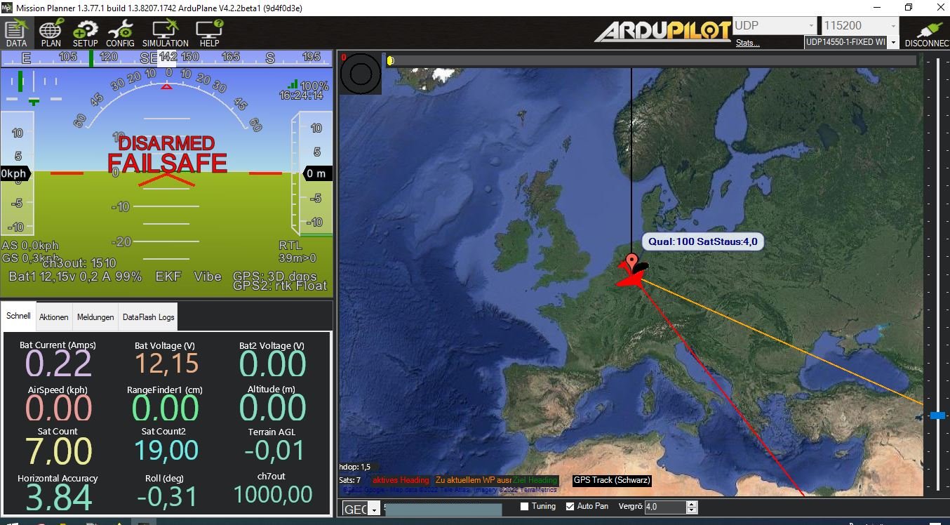
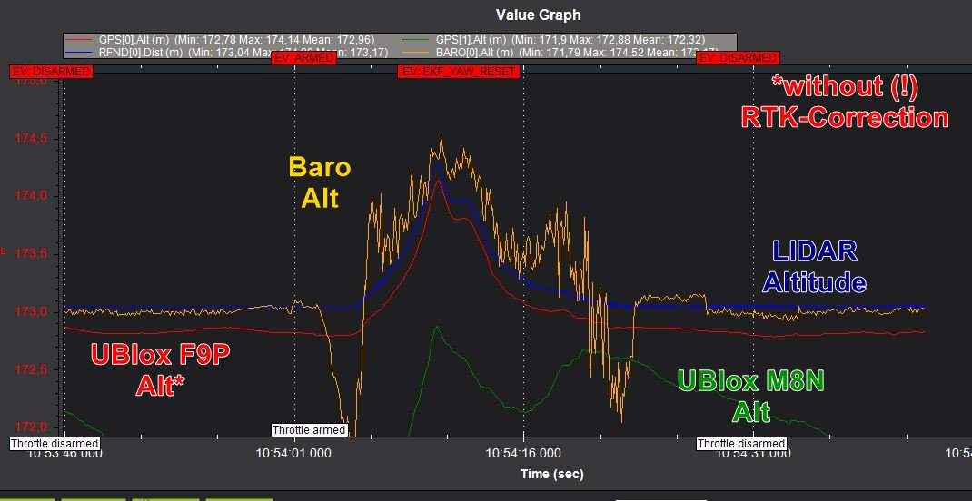
i was surprised how well the FP9 GPS calculates the altitude in contrast to a M8N even without RTK correction signal (the NTRIP telemetry will be injected later via the LTE connection)
-
I am glad that the electronics are working trouble free. The SDP33 is connected via shielded I2C bus line, the MS5525 is connected to a F103 whose CAN bus to the Matek L431 sends the Ublox F9P data and the Mauch sensor data via Can Bus to the flight controller without interference in the high current interference environment.
Next I want to test QLoiter extensively before I start the first transition.
Rolf
2 Likes
Rolf, encouraging flight test results!
I had a nice, stable hover last week after rebuilding my VTOL motor arms. Is that 5.5 Amps per motor for hover (you state 55 Ampere)? I am still right around 25-27 Amps hovering 12s for 10.44 kg MTOW at about 5 meter AGL (1470 m ASL).
I had one of my VTOL batteries puff on me so I am waiting for a replacement set before my next flight tests. In the mean time I have been reviewing the flight log.
Thanks for the heads up on the MP prop settings, I’ll try that for my next flight and compare the adjusted parameters.
Cheers,
Christian
1 Like
Hi Christian,
correct 55 Amp. at 12s all
I think that I may (hopefully!) have calibrated the MAUCH sensor incorrectly. In comparison with the 12s specified in this thread and based on the motor data T-Motor MN601-S I would have expected under 30 amps. I will look into the matter in the next few days and report.
Cheers
Rolf
1 Like
I hope that is the case too!
I am close to (slightly under) the expected Amps listed on the motor spec sheet for my MTOW and thrust required. I’m going to double check my config as well, probably put a multimeter on the VTOL (props off) to compare with my HUD and logs.
-Christian
In Mission Planner, getting ready to update, I see two versions of Cube Orange firmware. One w/ bdshot. Will wither work (not sure I need bdshot)? I have the MFE esc’s that came w/it.
Hi Mike,
You don’t need bdshot