Nice Rob, thank´s, yes, I learn a lot with your and Forrest discussions, I´m with vtol´s now and mount the motors like Greg do it with two motor mounts cross but looks heavier than that tecnique.
1 Like
My leaving was delayed by a day so I did an experiment today. My hex has round tubes for arms so I printed off a fairing to stick on the underside of the arm that would make it into an airfoil. I put the fairings on two of the arms on one side and flew it to see if it would effect the motor output to those arms. If it improved the drag it would show up with lower output to those 2 motors and higher output on the other side. In an undisturbed flow this would reduce the drag by a factor of 10. So far looking at the data it didn’t make any difference to the power required and this should be way more pronounced than the difference in square to round which is only a factor of 2. I want to play with the angle of the fairing a bit and run a couple more tests but it doesn’t look like this issue is worth worrying about much.
2 Likes
I ran a FEM of the torque box I 3D printed the other day. It showed a torsional stiffness of 0.5 deg/ft lb and that it should fail somewhere around 8 ft lb if it didn’t buckle first. I took it out to the shop and torqued it to 6 ft lb which it held fine but was beginning to show buckling in the compression members. It certainly shows that printing a whole frame from flat panels and gluing them together will make an efficient frame. Using plywood would be even better since the modulus is higher than ABS.

4 Likes
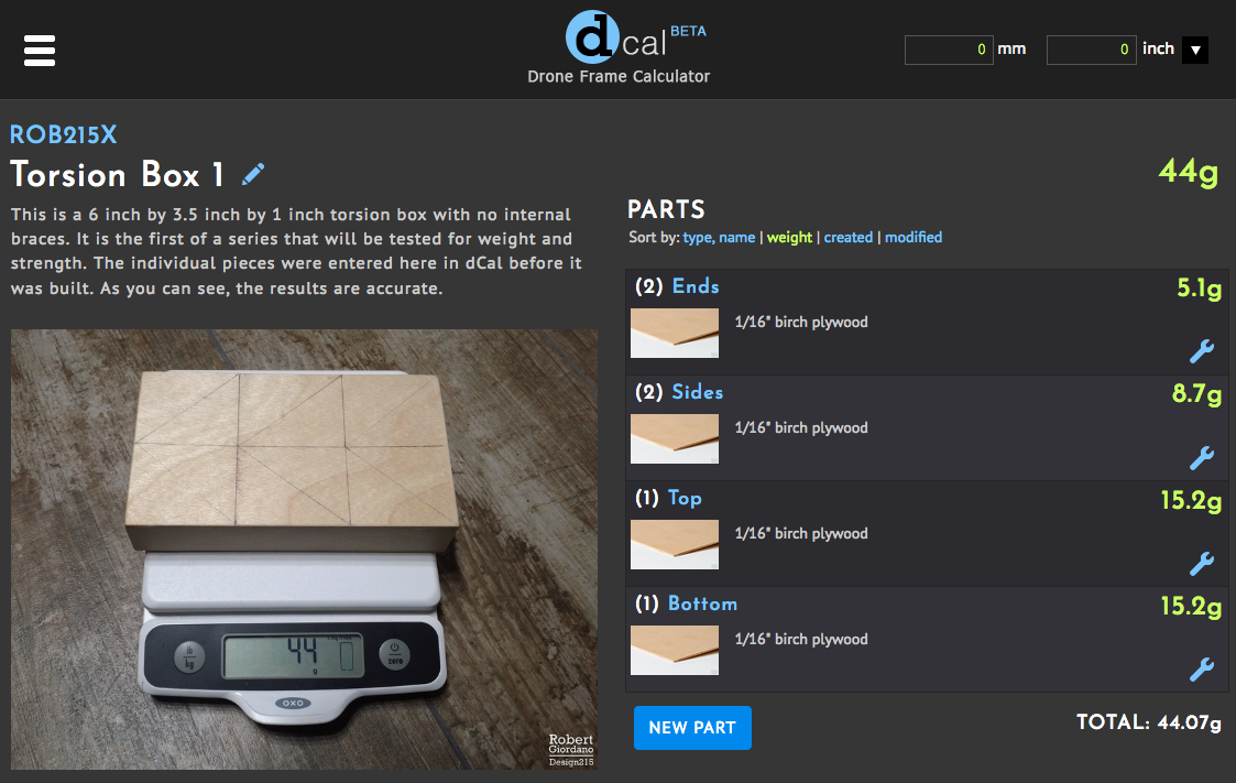
Here’s my torsion box, built to the same dimensions of 6" x 3.5" x 1". It’s not the prettiest box in the world but I was surprised how stiff it is.
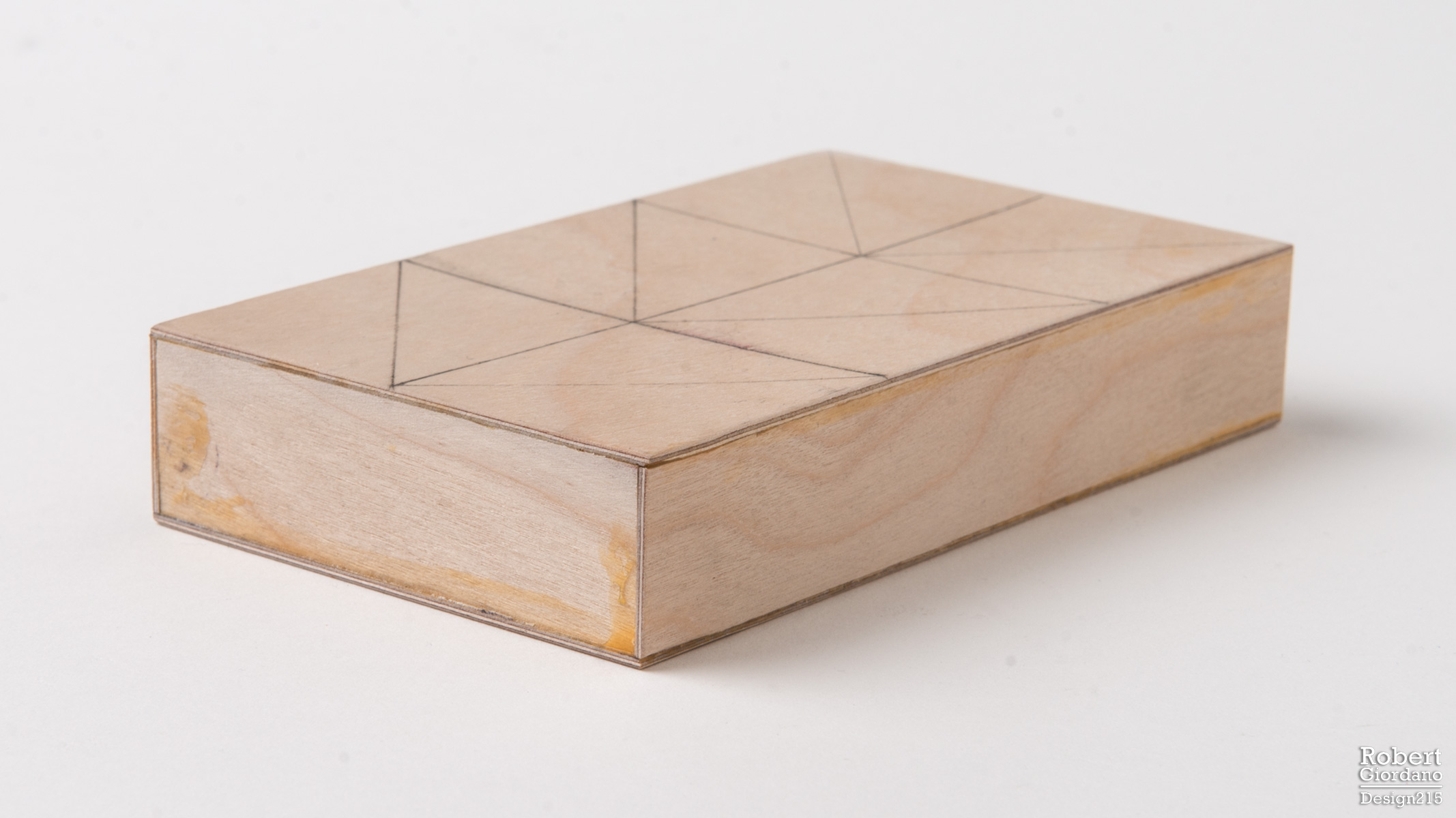
There are no cutouts yet because I wanted to weigh it and test it before I made any cuts. Before I even started making the box, I entered the pieces into dCal and the app showed it would weigh 44g. When I actually built it, that’s what it weighed.
1 Like
My robocat has something similar cf box and is really stiffnes, love that design.
1 Like
We used airfoil shaped carbon tubes on our big crop dusting multi with good results. Good flight times and very low vibrations
2 Likes
Tubing Calculator UPDATED to v1.2
I have updated the Tubing Calculator so it uses the torsional constant for a thin-walled closed section instead of the polar moment of inertia, as @Ragbagger suggested. The new results are not wildly different from the previous version, but they are more accurate now. Weight comparisons and deflection are the same as before. Only the torsional strength comparisons have been updated.
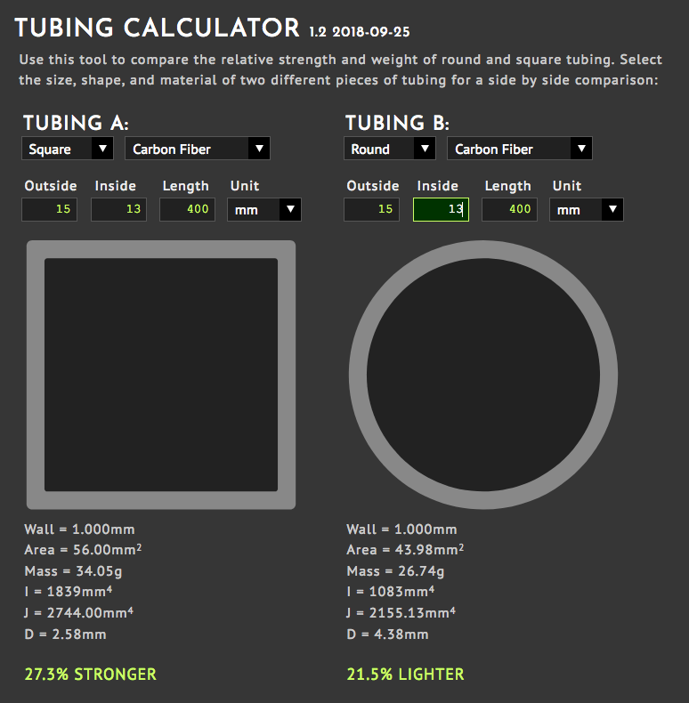
This example uses the same size tubes that @Ragbagger used in his example.
“J” is now the torsional constant for a thin-walled closed section (tubing).
1 Like
Rob,
I was thinking the same thoughts about the arms, that the best design would be a faired cross section. But the problem is the quad can fly at various airspeeds. I wonder if I have to worry about relative wind from forward motion. I guess no on a camera drone that only hovers but what about a racing drone?
A racing drone might cruise with a 35 degree nose down angle. How to fair the arms?
At 35 depress we have high body drag and maybe the props interact
I think at high speeds the goal is the lowest possible drag from the body and antenna andbarms and at the same time the projection of the prop disks in the forward direction needs to such that the “rear” props get the cleanest air
Yes. and THAT is where it matters. If the drone mostly hovers there is not much room to improve it. OK maybe add 2% to the flight time but the goal is to fly 60 miles per hour 4 feet off the ground in trees there is HUGE room to improve the current designs. Racing drones are actual more popular now then are camera drones.
I have a 3D printer and would be happy to work with some one more expert then me in aerodynamic
One more idea: If you own a drone you have a “free” wind tunnel. Mount the drone on a stand so the four pros are on a vertical plan and run the engines up. I have a wind meter, the kind on weather stations and I can calibrate the wind.
My goal is to make a mono coup 5 inch racing drone with minimum drag and all the parts inside. I’d put the design file online for anyone to print.
2 Likes
Hi Chris,
As you mentioned, drones that mostly hover won’t benefit too much from aerodynamic improvements and I agree with the 2% figure. The end goal is going to be the determining factor and much of my work involves either still photography or film production.
The initial goal of this blog is to design a frame for a 650 class quadcopter that:
- is both light and stiff, two of the most important factors for a camera ship.
- can stay in the air for at least 30 minutes fully loaded.
- can be built by anyone, especially students, with no special tools, no 3D printers, etc.
- can be built without exotic, difficult to source, or expensive materials.
I picked a 650 class drone because it seems the most practical for a wide range of action cameras and gimbals. This size drone with 15" props has a similar footprint to the DJI Inspire, which is what many people are using in film production these days.
I am very close (maybe another couple of weeks) to building a working prototype of my latest frame and posting the plans online. I will be building two identical frames, one with arms made from round tubing and the other with square tubing. I will be testing them against each other to see the difference in forward flight.
There is definitely a need for fast, forward flight beyond racing drones and this includes film production. Whether you’re shooting a car commercial, following a boat pulling a wakeboarder, or following dirt bikes on a trail, there is a need for camera drones that can fly at 25 to 50mph.
If you look at the DJI Inspire, some effort went into its aerodynamics. As it leans forward at different angles, the profile remains almost the same. But the Inspire fails when it comes to weight. The Inspire 2 is 3690g AUW with the X4S, their smaller camera, and 3900g with the X5S, their better camera. Even if its kind of aerodynamic, its still a flying brick imo.
So, I’ll definitely be getting into all of these things because they all need to be addressed.
1 Like
I looked at the DragonPlate web site and see they offer streamlined, airfoil shape tube. Would be good but each stick costs $125. Perhaps we look at how RC airplanes are made and use a hot-wire cut foam fairing over square or rectangular tube?
An interesting experiment after you have data on the two frames you are making would be to fair the square tubes and see if they outperform the round ones. For a quick test balsa sheet would work
One other reply odd-ball sounding test method, but it works. Black box recording of ESC telemetry. The drone will actual fly with DIFFERENT props on each arm. You hover the drone with one of the four props swapped out then look at the motor current and rpm for each motor. In hover the computer is making 100% that each motor is making the same thrust and lift. Examine the log and see if current is reduced or increased for the one non-mating prop. Could to the same by fairing one one arm. Then you have data under identical conditions.
With on matched props the drone’s performance is limited to the lowest performing prop, the computer will do it’s job and keep the drone from tumbling out of the sky. Some people think it can’t work but try it. Hover one foot off the ground over soft grass so there is low risk. The log gives a good A/B test.
This kind of testing is best done with Cleanflight or Betaflight because you only need to fly it line of sight manually and you are only collecting data on the SD card.
With e smaller size drones I experiment with I can 3D print as set of arms with very complex shapes and it costs me 1.9 cents per gram for the materials. Frames are coming out under 200 grams. PLA is not nearly as strong as carbon with this small size it does not matter.
4 Likes
That sounds like a really cool idea! I will definitely experiment with that!! First, I have to build this frame and I’m pleased to say its very, very close. I know I’ll probably make something even better in the future but I want to at least build my current design, fly it, and document its performance. I’m pretty sure it will outperform any commercially available, 650-class drone or drone kit on the market. =)
Interesting idea indeed. The problem (the FCU, with the exception of the PID setting, wouldn’t care about the difference) would be trying to baseline the result.
- on a well-built (most aren’t) test stand, you can precisely control each test
- but, if looking at relative performance (the odd out rotor versus the other three), as long as the flights were quite similar, that might work.
… so not absolute numbers
… but relative numbers using
i. Motor channel PWM values (e.g., for a quad, RCOUT CH1, CH2, CH3, CH4)
ii. not sure if there is anything else in the logs
… would not be able to accurately derive efficiency numbers from PWM, but would be able to get ordinal if not close
1 Like
Plywood Box Torsion Tests - Solid vs Cutouts
I’ve confirmed @Ragbagger’s design by testing my 2mm (1/16") birch plywood box, both with and without any cutouts. On my torsion test stand there was no perceptible difference in stiffness between the solid box and the same box with cutouts, even though the cutouts resulted in 20% less weight.
The next step will be to make some longer boxes and test those as well. The frame design I’m working on will use a box that is 310mm in length. I will be testing a 25mm height (same as the box in the video) but I also want to compare 20mm and 30mm heights at the full 310mm length.
My next frame design will be flexible and efficient enough so if you don’t have a Dremel, router, or an easy way to do the cutouts, you will still have a very efficient frame with longer flight times that most commercially available drones.
3 Likes
Rectangular beams would give better results than round or square with the same weight. It is also easy to find rectangular beams. Holes in areas of low stress could help to reduce weight even more, with little effect on stiffness. Slightly better could be an oval or diamond shape beams. Both will improve the efficiency of the prop over the arm, but are difficult to find in carbon fiber.
Yes and no. There seems to be a lot of confusion on this topic. Since I’d like my blog to be an educational resource, I’ll try my best to help clear this up. I’ve already touched on this earlier in my blog, but here goes:
- For students visiting this blog, when we talk about TORSIONAL strength, we’re talking about how well something resists being twisted. When we’re talking about DEFLECTION strength, we’re talking about how well something resists being bent.
- At the SAME WEIGHT, round tubing will be stronger than square or rectangular tubing. I am specifically talking about torsional strength. This is simply because the at same WEIGHT, round tubing will be larger.
- At the SAME SIZE, square tubing will be stronger than round tubing. Again, this is torsional strength.
- If you take a RECTANGULAR tube and orient the longer sides vertically, you will gain strength in deflection vertically, while losing strength horizontally. This might be more important for heavy lift drones and X8 configurations where you have 2 motors and props at the end of each arm.
- The efficiency of the prop as it passes over the arm is a more complicated problem that involves aerodynamics but also involves natural frequency, harmonics, and vibration. We’ll get into this in more detail later. I will be building two identical frames but one will use 15x15mm square tubing, while the other will use Rock West 15.1mm round tubing. I’ll be comparing them to see if I can detect any difference in efficiency.
All of the variables have to be considered and some design choices will depend on the mission. For this blog, we’re building a lightweight, 650 class drone for photography and video. The goal is to find the best combination of light and stiff using easily sourced materials.
Here are my top 4 tubing choices for this particular project: (click the image for more details)
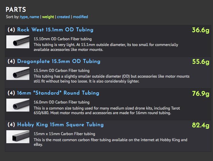
The weights listed are for (4) arms where each arm is 27cm in length.
The two heavier ones are the cheapest and easiest to find. The two lighter choices are more expensive and not always available. If anyone has other choices that fit into this range as far as weight and strength, please let me know and I’ll check it out.
2 Likes
13 - Prototype Frame v2.4.9
Here’s the next major improvement to the v2.4.7 frame I posted here back in April. I never posted v2.4.8 because it was a transition to this frame. I’m actually going to build and fly this one. I’ll be building two of them- one with round tubing and motor mounts, the other with square tubing, which is heavier but will not require any motor mounts.
The Design v2.4.9
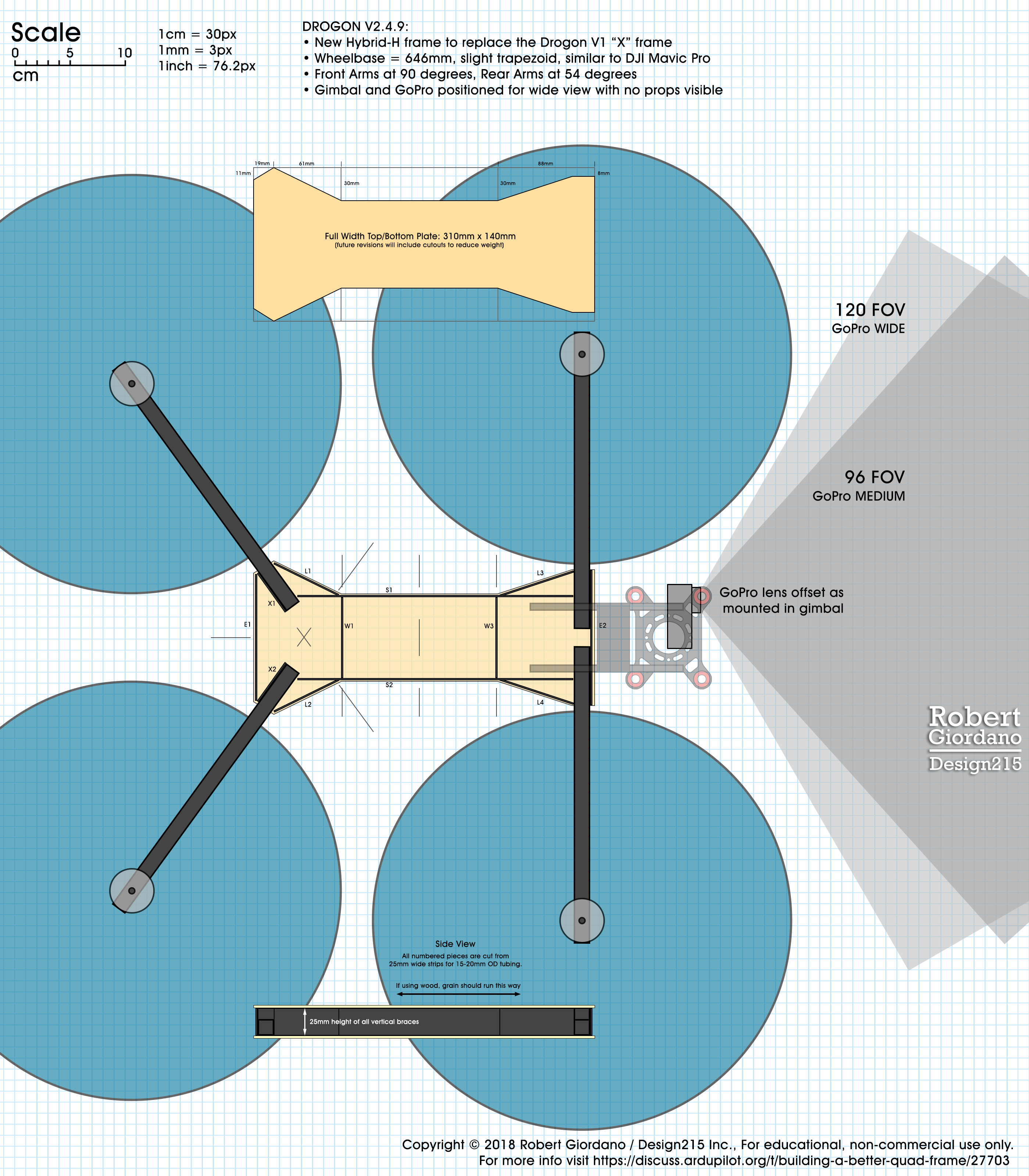
(Click the image to download the full size drawing from Dropbox)
I make these drawings to be printed at 100% scale. When printed properly, you can put a centimeter ruler on it and the grid lines will be exactly 1cm squares. I bring the file to my local FedEx Office on a thumb drive. They have a printer that lets me make 24" x 36" black and white prints for $3 each. Back at home, I use the drawings as templates to align and glue the pieces together. I use the guides on the drawing to mark where I’m going to cut the pieces.
About This Frame
I’ve made a number of improvements to this frame over my previous designs. The overall size and wheelbase is the same. It supports 15" props like most 650mm class kits. Here is a list of the changes and improvements:
- Optimized for a front mounted gimbal/camera. The motor layout is now a slight trapezoid instead of a square. It is almost the same motor layout as the DJI Mavic Pro. I did this mainly to bring the camera back, closer to the frame and still allow the WIDE GoPro view without having any props in the picture.
- Stiffness is achieved using a closed box design. My previous frames used a truss design, which was slightly lighter but not as stiff in torsion. With the truss design, there wasn’t much room to make it lighter. With the box design, carefully placed holes can be cut in the box without affecting its stiffness. Thanks to @Ragbagger for the input on this.
- This design should be easier to build. There are fewer pieces to cut and there are no interlocking pieces that need perfect notches cut in the middle. It should only take 2-3 hours total time to cut all the pieces and glue this together. As usual the arms will be glued with epoxy so that requires waiting 24 hours and coming back the next day to finish gluing the rest of the pieces with wood glue. Still, you could easily build a couple of these frames at the same time, without a lot of extra effort.
Why Did You Use Wood?
Like I mentioned earlier in this blog, I use birch plywood because:
- Its cheap. For $30, I have enough wood to build 2 frames.
- Local arts and crafts stores usually have it in stock.
- Its lighter than carbon fiber and is still fairly strong.
- Its easy to cut.
- Its easy to glue.
All I see is a diagram. Where are the Instructions?
Ah yes. Well, I don’t have those yet. BUT, I’m going to be making a series of videos that I’ll be posting on YouTube and then here, showing you step by step how to put this thing together. You might want to wait for those because I haven’t built this frame yet and I might discover things that I want to change. As I mentioned earlier, I’ll be building two of them, one with round tubing and one with square tubing. The one with round tubing will require motor mounts and I haven’t decided how I’m going to do those yet.
In conclusion, I think I’ve tweaked this frame enough that its ready for some actual flight tests. I’m looking forward to posting my progress as I put this thing together.
3 Likes
Sorry for missunderstanding the calculations about torsional stiffness. Of course, what you say is right, in fact, torsional stiffness of the chassis is important in H configurations, if not an oscilation like a waist twist could occur. But torsional moments in the wing arms are low, so I would prefer to increase the longitudinal stiffness rather than the torsional moment for the wing arms. A drone with flexible arms is unflyable.
1 Like
Drogon v2.4.9 frame on DCal
Yes, its been a few weeks since my last post but I don’t always have enough spare time for all of my projects. Your patience is appreciated. I just updated the design on Drone Frame Calculator and you can see it should weigh 177g without any cutouts. That’s already pretty light but it will be even lighter once I do the cutouts.
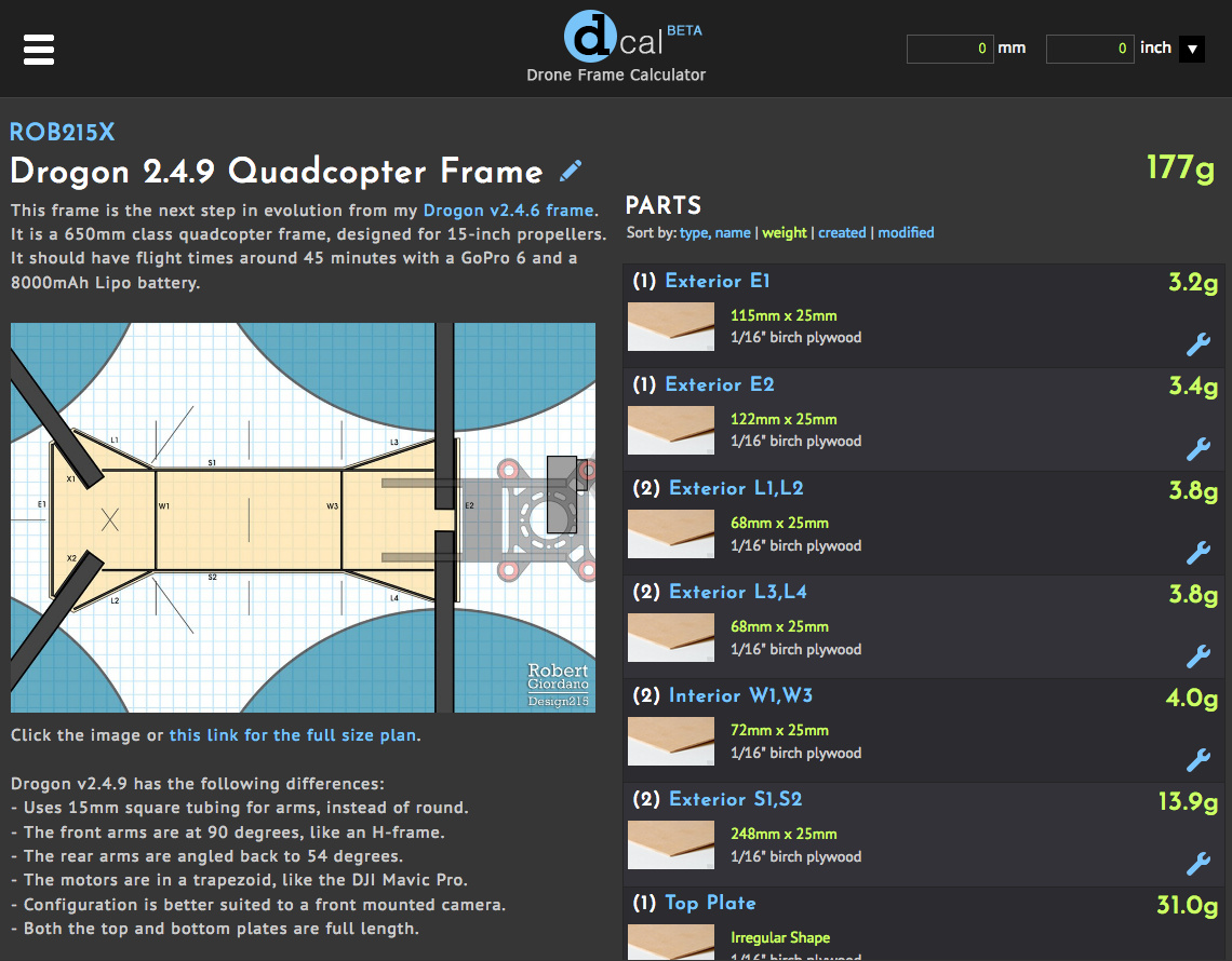
Click the image or this link to go to the page.
I’m working on the first video which is just an introduction but it shows how I print the frame design and use it to get all of the parts lined up perfectly.
3 Likes
I like the concept of a closed box as the central part of the frame on which arms are connected.
In the DIY spirit, with no sophisticated tools nor machinery, apart from assembling wood pieces to build the closed box, couldn’t a large diameter plastic pipe (PVC for example) do the job ? (arms are then simply passed though holes made in the tube)
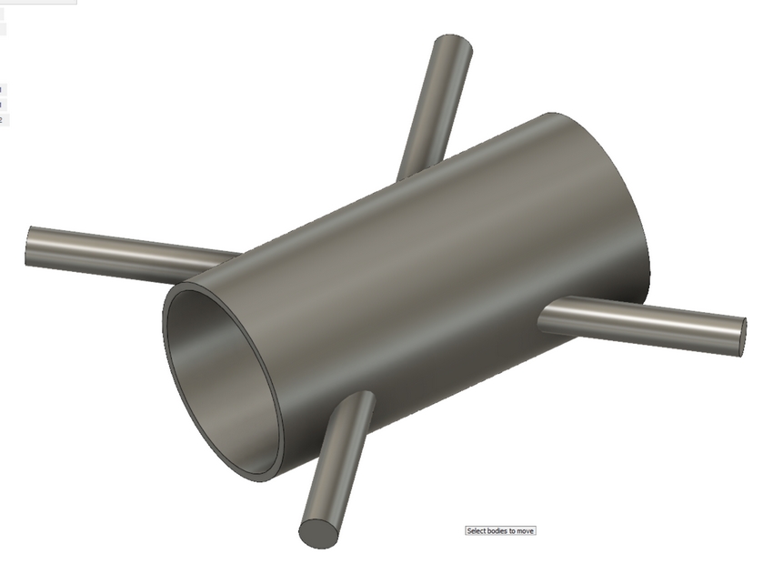
Robert, have you tested on your bench system how a large CF tube or large PVC tube used as the body of the frame would do ?
Something like this:
2 Likes