I used 15x15x800mm carbon fiber square tube to build my frame.
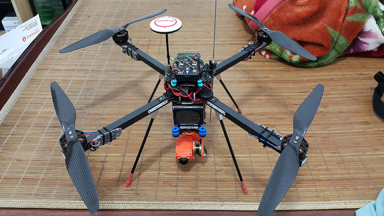
It’s very durable,strong,and light. I build two quad 525mm and 650mm size as those pictures.
650mm quad’s weight is 2270g include 6S4P Li-ion battery, and over 50min flight time.
I think maybe it’s not the best frame,but it’s good for me.
For your reference.
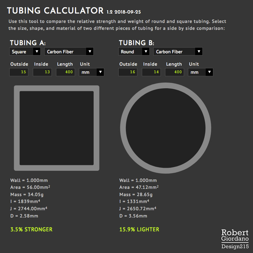
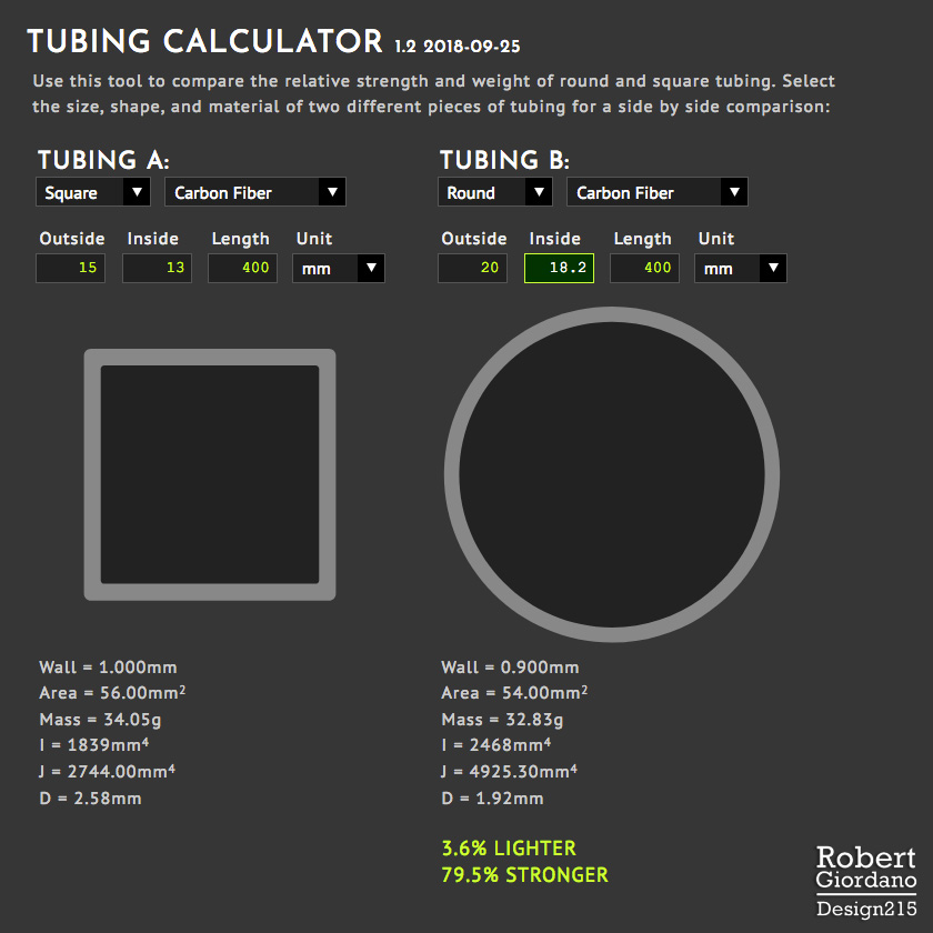
UPDATE: These images reflect the new formula used for comparing torsional strength.
I’ve included some of the same information I first posted in this blog, back in April. After searching the internet and playing with many online calculators, I couldn’t find one that let me compare two types of tubing side by side, gave me the torsional constant for a thin-walled closed section AND estimated deflection, and worked well on my tablet. Also, I didn’t see any other calculator generating graphics that are perfectly to scale. I hope you like it.
I just finished this tool last night so if you find any bugs or see improvements I could make, please send me a PM. Thanks! I have a LOT more coming!!
It is actually easy to make a mold and lay down the carbon clothing resin, All using only simple hand tools.
If you are doing this at home you are not going to use an autoclave. C-clamps work and provide enough pressure for a small part like a drone body.
carbon/epoxy can be rather low-tech if you want it to be.
3D printing works too. You can print a stiff and light frame of you make the shell thick enough. Make it light be printing the in-fill at very low density, say 10% to 30%
Now I do Also - how did you film the qav400 crash in episode 2? It looks as if the main camera is following the quadcopter. We’re three cameras on board?
Yes, 3 cameras. There’s a 7mm x 300mm carbon fiber tube extending backwards with a 808 Keychain camera attached to the end, hanging under it. Until I watched that camera I had no idea what was going on with my frame. I learned a lot from that experiment.
Hi Rob,
I just found this thread and thought I would throw in a couple comments. I’m an aeronautical engineer and have been designing airplane structure for about 40 years now for a small airplane company in Seattle (Boeing). I have been messing with drones for a while and want to embark on a custom build for efficiency so I have found your posts to be excellent. The comments I would throw in are these:
There has been discussion of torsional stiffness and ways to increase it using truss structures. In fact the most efficient way to increase torsional stiffness is by using a closed section. All current airplanes use a closed box section in the wing as the primary torsional stiffness. Truss work went out when stressed skin designs took over. If I understand your current build in plywood it looks like you have an open section in the center on one side and open on the other side on each end. If you cover the center section you can leave out all of the diagonal bracing and have a more torsionally stiff section. There is no need for any sort of core unless you want to make the skins so thin they lack stability.
One topic I have not seen addressed (maybe it has been in other forums) is the loss of efficiency when the prop goes over the arm. The arm in essence is blocking a percentage of the prop’s thrust. The amount of blockage will be proportional to the arm’s cross sectional area and to the drag coefficient of the section. A square section has about twice the drag of a cylindrical section so this effect would be double for the same size square tube. If one was to fare in the cylinder to a symmetric airfoil shape it would drop the drag to one tenth of that of the round tube! So keeping the arms as skinny and as aerodynamic as possible should have a large impact on efficiency. Another spin off on this topic is that the prop- arm interaction will also cause vibration. There will be a pulse to the airframe as each prop blade goes over the arm. I want to build a test rig to test some of this with different arm shapes.
Thank you so much for contributing to this discussion. This is exactly what I wanted. Your points are completely valid and I’ll address them:
I completely agree. Maybe I’m not using the right terminology but much earlier in the thread, I mentioned a monocoque structure being the best and showed examples of commercial drones where the “shell” of the drone provides its stiffness. These are usually injection molded plastic frames.
The overall theme of this thread is about building a frame from scratch without the need for special tools, exotic materials, and equipment the average person doesn’t have access to. So, I’ve been trying to design a frame that can be built by hand, with materials you can get at the local arts and craft store, using basic hand tools.
Believe me, I’ve been trying to come up with a frame that uses a closed shell design, that would be easy to build, but they always come out heavier than my truss designs. I haven’t given up though because, a) I’d like to put all of the electronics inside the frame to protect them from the elements, and b) the entire ship would be more aerodynamic. The main reason I’ve been developing my Drone Frame Calculator is so I can calculate the weight of many different frame designs without having to actually buy, cut, and weigh all the pieces.
Again, I agree but my question is, how much does that actually affect flight time and performance? I agree with keeping the arms as thin and aerodynamic as possible but the availability of materials is also a consideration. On a ship with a 20 minute flight time, do square arms cut the flight time by 2 minutes or by 20 seconds? On ships that use a box shell design, like the DJI Phantom series and the 3DR SOLO, the arms are much wider and block a considerably larger area of thrust than frames using carbon fiber tubing of any shape. With larger drones like the DJI Inspire, why do they use carbon fiber tubing with a larger diameter than would seem to make sense? I’m trying to figure than out as well. Finally, there is the DJI Mavic Pro, which uses square tubing for its arms and is advertised as “having the longest flight time of any commercial drone”. (which is only 31 minutes, lol)
At the end you mentioned vibrations. I’ve found this gets complicated because it also has to do with the natural frequency of the components. To test some theories, I’ll be building 2 identical frames but one will use round tubing for the arms and the other will use square tubing. The square tubing is heavier and stiffer but won’t require motor mounts, while the round tubing is lighter and will have motor mounts. I will compare the vibrations and efficiency of both designs.
Finally, I’ve made some improvements to the previous design posted in this blog. The middle section will be enclosed and I’ll be testing it with and without the diagonal braces in the center, using my torsional test stand. I’ll be posting that design here soon. =)
Hi robert,
For monocoque, if you cannot go thinner on the material a truss structure will win. Not that a true truss structure does not have any solid skins on the outside. Internal truss elements due very little for torsional stiffness, they need to make up the outer surface and enclose the box space. To make it simpler you could make a four sided box and then drill lightening holes in the unstressed area to reduce weight. I will see if I can get you a sketch of what I mean. If you want to compare torsional stiffness of various designs without having to build them and test them, I have some finite element software that can easily model box structures and apply a torque to it. I will be busy until the beginning of Oct though, after that I can provide some assistance.
My guess on why the produced designs have wide arms or poor drag characteristics is that this sport has been built primarily by controls guys, not aeronautical engineers. It has been all about the control algorithms and computing power up to now. I don’t think DJI had any aero guys, just look at the original Flamewheel arms. they are really poor from both a structural and an aerodynamic standpoint. The other point on the aero drag is about the use of the drone. The stuff I was talking about would come more into play for a slow or hovering drone like a camera platform where the prop wash is pretty much straight down. Once you add forward velocity, the airflow gets pretty confused and making an aerodynamic design would need either costly CFD analysis or wind tunnel testing.
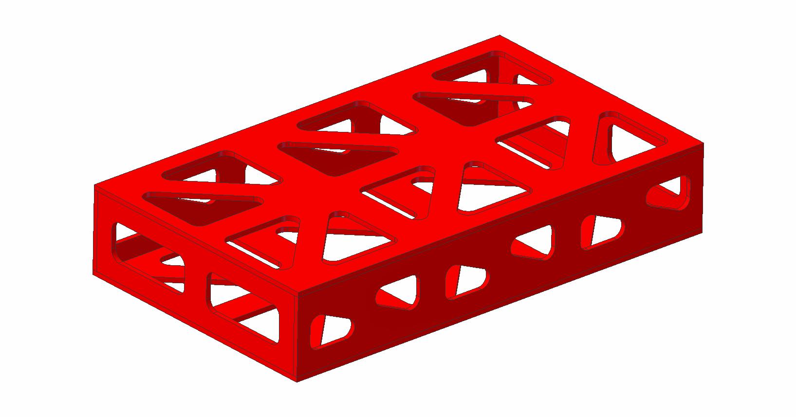
Here is a sketch of an efficient torque box made from flat panels cut into a sudo-truss arrangement. The torsional strength would be governed my the buckling stablility of the diagonals. The shallower the angle of the diagonals, the stiffer it will be. I didn’t know your dimensions so this box is just an example. If it buckles at too low a load rib posts could be added at each of the hubs where the members come together.
Thanks, that’s very cool. Many of the drone frame kits come with carbon fiber plates that are milled with cutouts in a very similar pattern. The problem is, these kits end up being extremely heavy because, instead of gluing the panels together like your drawing above, they include all kinds of aluminum spacers and steel bolts.
For a DIY drone frame, the following factors come into play:
Availability and cost of materials. Many times, the “ideal” material isn’t available.
Availability and cost of tools. Many people don’t have milling machines or 3D printers, although new online services are making these things more available at a lower cost.
Knowledge of material strength, adhesives and bonding techniques, and the use of specialized tools is beyond many people who might want to build their own drone.
I’m trying to do something about number 3 while keeping 1 and 2 in mind. For example, Nomex is an amazing material but I’m not using it in any of the designs I post in this blog because its very expensive and isn’t nearly as accessible as say, 1/16" birch plywood I can buy down the street at Michael’s Arts and Crafts.
Have you seen the tools I’m building to help people (including myself) experiment with drone frames? I’d love it if you checked out the following links:
https://design215.com/dcal/u/examples “Examples” is a user account on dCal for demostrating the app. The next two links are listed on this page but I wanted to draw specific attention to them.
https://design215.com/dcal/u/examples/h4-alien-680-frame Here’s a commercial drone frame kit broken down piece by piece. The weights for the individual parts were not entered manually, but were calculated by the app using the entered quantity and dimensions.
https://design215.com/dcal/u/examples/tubing-comparison This is a comparison of 4 similar sized pieces of tubing that could be used for a quadcopter. The description introduces my Tubing Calculator app and shows example screenshots. The Tubing Calculator uses HTML5 and SVG to render pixel accurate, scale models of any tubing sizes entered.
I will take a look. My idea with the model posted is that you can make it out of 1/16" ply quite easily. For grins I 3D printed one today in 1/16" ABS. The one I printed is a 1"x3.5" box 6" long. It came in at 39g and is really stiff in torsion. I am thinking of doing a X8 frame made up of only 3D printed flat panels like this and graphite tubes for arms. When the glue dries I am going to test the one I made to failure to see the failure mode. One could easily design a frame like this that one could just print out on paper and use it as a template on 1/16" ply.
Many of the drone kits that come with truss like cutouts and spacers are terrible designs for weight. It is clear they have no engineering knowledge for weight efficient structure. The spacers have virtually no shear load path and introduce point loads in the panels where they are fastened. Usually they have the cutouts in the wrong place. Very heavy for the strength.
That is correct. I was staying with the direction of this blog in making something from available materials and simple tools so I made the torque box as flat panels that could be cut out with a knife or saw. I was too lazy to cut them out of wood so I just printed an example. It came out stiff as hell. If you want stiff you have to have all four sides on the box.
Hi Rob,
I took a look at the tool box you have so far and I have a couple comments.
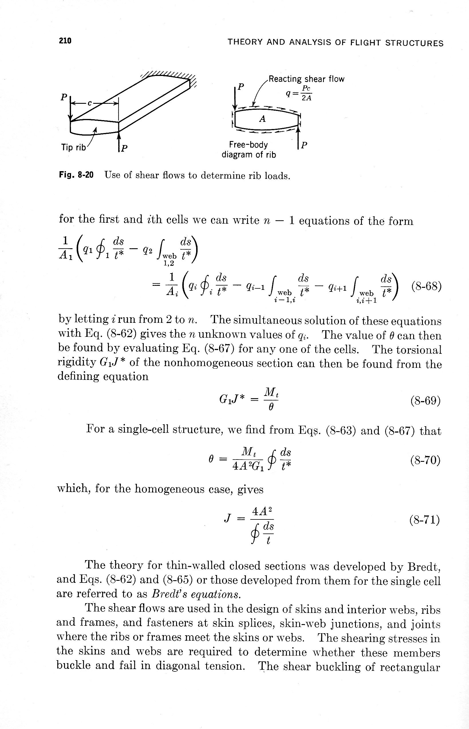
In the tube comparison you have J=2I which is correct for polar moment of inertia but it is incorrect for calculating torsional stress or deflection in a thin walled section. J for a thin walled closed section is given by: J=4A^2t/S where A is the cross sectional area at the mid line of the wall, t is the wall thickness, and S is the perimeter measured at the mid line of the wall. For the example of an internal dimension of 13mm and outside dimension of 16mm as in the example:
for square:
A=1414=196
t=1
S=144=56
J=4196^21/56=2744
for round:
A=14^2pi/4=153.94
t=1
S=14pi=43.98
J=4153.94^21/43.98=2155.3
This gives a stiffness improvement of 2744/2155.3=1.273 or 27.3%, not 38.2%
It should also be noted that this applies to stiffness only. For strength calculation the sharp corners on a square section will change the failure mode and in composite may well be lower than the circular section.
In the battery calculator it shows a linear relationship. The useful capacity of a Lipo battery drops as the current increases. You can increase the useful energy in a battery by discharging it slower. This is traditionally calculated with the Peukert formula. Here is a paper on the Peukert formula applied to Lipo batteries: http://www.mdpi.com/1996-1073/6/11/5625/pdf
The Peukert formula is C=T*I^k where C=capacity, T=discharge time, I= discharge current and k is the Peukert coefficient. From this paper it can vary from 1 to 1.3 for a Lipo. At 1.3 it is a huge effect.
Unfortunately suppliers don’t provide k (unless they are very good batteries). If you know the capacity of a battery pack at 2 different discharge rates you can calculate k. This is why you see a different size and weight for the same capacity battery pack rated at 10C versus 65C.
If you don’t find an error on those pages, then I will look at my code and figure out where I made an error. Please let me know. Thanks!
Next, thanks for the Peukert formula! I will definitely look into that!! What’s interesting is, the discharge of the battery (as shown by time vs voltage) in the last drone I built was fairly linear. But, it was only using about 20% throttle and 9-10amps to hover.
Hi Rob,
Both of those sites have the same error. J=Ixx+Iyy only works for solid sections and thick walled hollow sections. The equation for J for thin walled closed sections such as these is as I quoted. For reference I have attached page 210 from “Theory and Analysis of Flight Structures” by Robert Rivello. See equation 8-71. Thin walled open sections such as I beams or C channels is another type of calculation all together. If you are interested I can provide that as well.
When pulling low currents on a battery you are well down the Peukert curve and get maximum capacity from the battery. On my 700mm hex I run 30V (8S) to keep the current low. I can use a 10C battery. This helps get the most out of the battery and I can reduce wire gauges and save some weight. I get 40 minutes on it and I am carrying a lot of weight.
Rob: how do you fix the motors directly to the square tube? with only two bolts? you use some kind of filling material not to fatigue the tube?, thank´s.
Following this interesting discussion.
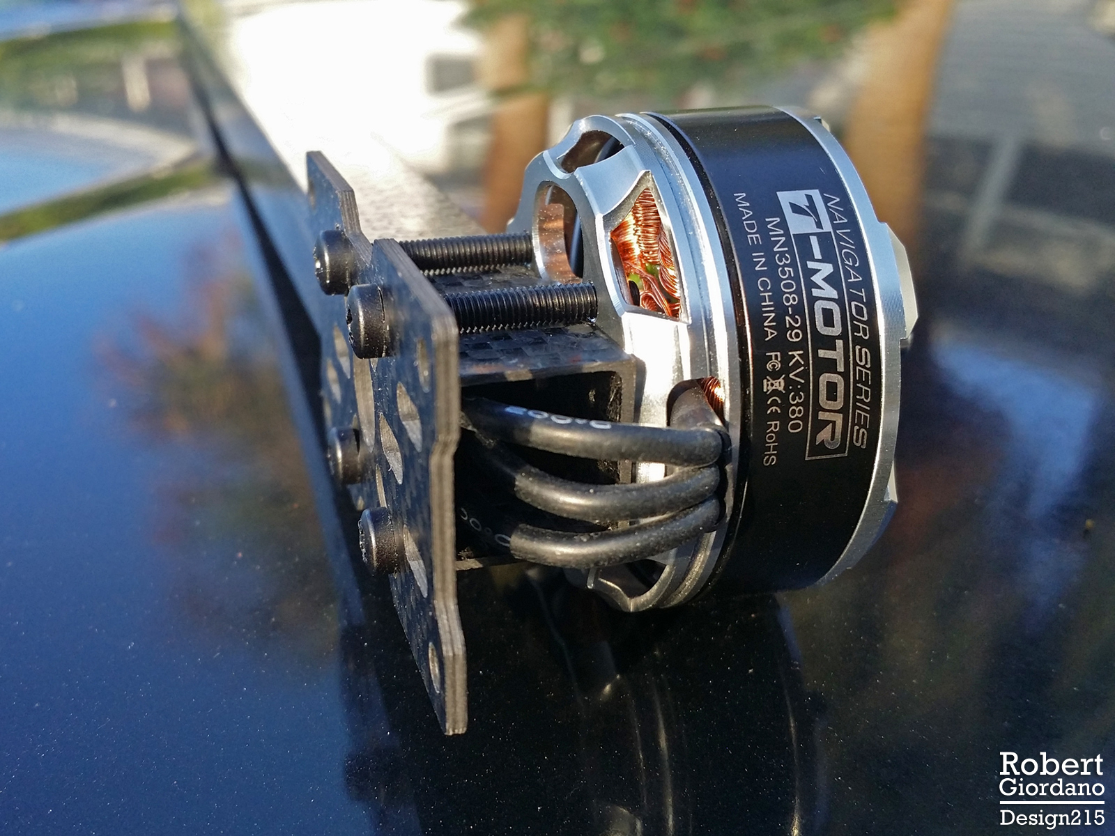
It’s nice to see you over here! I remember you from the DIYdrones forum. Anyway, I just went outside to take a picture with my phone so it is not the best but it shows the arrangement…
As you can see this is a special case where the bolt holes in the 3508 motor just clear the outside of the 15mm square tubing so there are no bolt holes needed in the tubing and no filler material is needed inside the tube. For now I just used a motor mount plate I had laying around but I will replace it with a smaller plate when I actually put it all together. I had to drill one hole in the top of the square tubing for the motor shaft and retaining clip.
I will be building two identical frames, one with 16mm round tubing and motor mounts, the other with this setup. I’ll be comparing the two for weight, performance, and ease of build.

 Also - how did you film the qav400 crash in episode 2? It looks as if the main camera is following the quadcopter. We’re three cameras on board?