Big 30Kg turbine heli tuning AC4.1.1

Hello Bill,

I make flight today with attitude fast, I let atc input tc to 0,2, as I make the tune with this value.

I make first hover in loiter with land, and after I make althold flight with sharp roll and pitch.

I tried to determine atc_input_tc and max axel on each axis but I find differents values.

Maybe you can what and tell me what you think about ?

@kuspower I looked at your parameters and you definitely need to change these
H_RSC_RAMP_TIME
H_RSC_RUNUP_TIME

The ramp time is not as critical as it is the time to ramp the throttle output to the ESC but the Runup time is VERY important to have correct. This is the time it take for the rotor to reach flight rotor speed. If this is not set correctly, the autopilot could take off at low rotor speed and CRASH.
Please make the RUNUP_TIME the time in seconds to reach the flight rotor speed. Looks like 25 seconds from your log.

As for the ramp time, change it to 1 second. Although you set it to 0, it defaults back to 1 in the code.

@kuspower also it looks like you have a bad 2/rev vibration. How many blades is does this heli have. I see that you notched the 1st, 4th and 5th. In my opinion, I would have notched the 1st, 2nd, and then your choice on the last one. But the 2nd harmonic is definitely showing up in the data.

Thank you for the rsv param, I know it, is for that I always arm and take off in stabilize mode. I will change runup_time param to 30sec before the next flight.

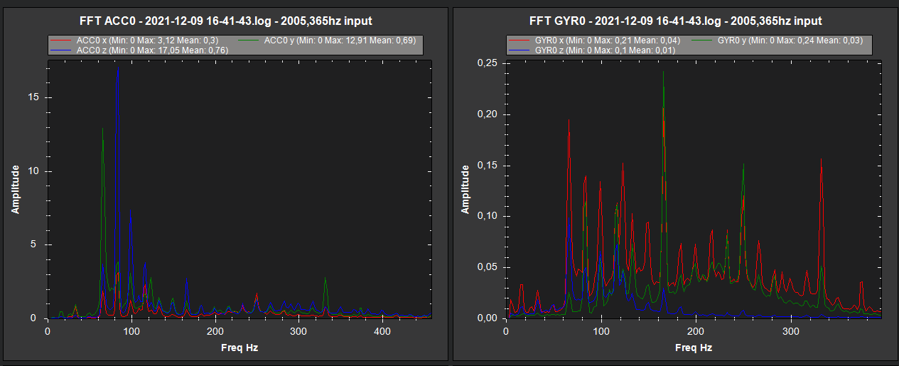
About harmonics heli is 2 blades rotor with 3 blades tail rotor.

First I set harmonics to 1,2,4 as marked in the heli tune guide, but with that setup, looking in flight vibe levels near 30 and lookinf fft i saw many more powered levels of vibration in front of the 4,5,6 harmonics.

For that I set the hnotch to 4,5,6 and result in lower vibration levels (below 15) in flight.

I will retry with 2,4,5 for check.

Regarding the atc_input _tc is realy dificult to find the good value. Please look at strang behavior I have with yaw.

I have constant 4 - 5 hz oscillations. I set rate d and p gain at there maximum to try to get more precise yaw.
Also increasing atc rate accel yaw max to big value (much more than tail rotor can give) reduced the amplitude of theses oscilationsā€¦

seems to me that there is 180 deg phasing that lead to this issue.

How to resolve it? This can be due to atc input tc 0,2 ?

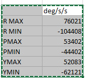
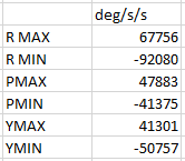
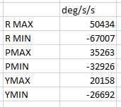
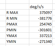
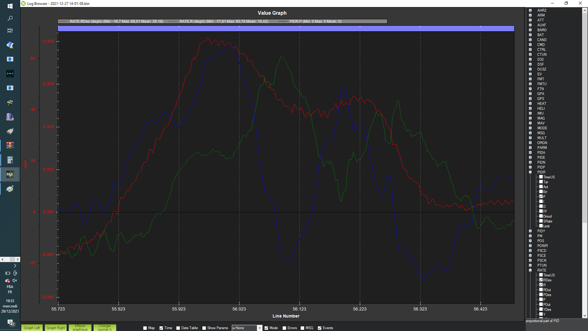
About accel logs revelated that on roll I get 1050deg/s/s and pitch I get 450deg/s/s.

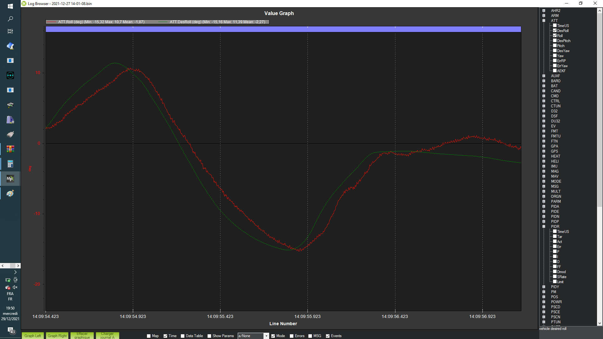
Idem as for yaw, to get more precise behavior I needed to push atc accel pit/roll max above what this heli can do, resulting in flyable heli, but far from I want achieve in terms of attitude. Also D and P are tuned as explained on the guide. Vff also are tuned as explained.

I suspect all this was caused by bad atc_input tc for this heli

Looking logs I donā€™t find the valueā€¦ can you please help me and tell me whitch value you can determine looking my log?

In order to find the capability of the heli you will have to set the accel_max really high and the input_tc really low. That way the command model wonā€™t limit the response of the heli. I recommend that you set the accel max Params to over 100000 and the input tc to less than 0.1. You just need to be aware that you could see feedback instability by setting these higher than what you tuned the rate P and rate D gains. So just do a hover to test the settings and be prepared to land if you see an instability develop. If there are no instabilities then perform the sharp stick inputs and you should be able to determine the capability of the aircraft.

The yaw axis is not affected by the input_tc parameter. Only the pitch and roll axis are affected by this parameter in stabilize mode or any mode that uses stabilize controller.

hello Bill, below raw fft befor HNOTCH (I cutted takeoff and landing data to analys only vibration in flight)


As you can see its dificult to set corretly the HNTCH for my heli.
we have big spikes@4,5,6,7,10, and 20th harmonicsā€¦ above 0,15 is 4,10,15,20ā€¦
but we can only set 3 below 8thā€¦

about accel max RPY measurement, and make excel analys with filtering from the 400Hz rates loging, I filter it with low pass filter.

Here is what I get:
50Hz filtering:
image
40Hz filtering:
image
20Hz filtering:
image
200Hz no filtering:
image

Question is regarding this, wich filter you advise me to use and set for basic/R/P/Y flte fltt?
Wich value off accel I consider for set RAT ACCEL MAX RPY params ?

thank you so much for your help.

Rgds.

True but the 2nd order low pass filter can attenuate the higher harmonics because there is enough frequency spread between the LPF cutoff frequency and these higher harmonics to provide good attenuation. You want to use the harmonic notch at the lower frequencies where you canā€™t get good attenuation of the vibrations. Thus it is most important to notch the 1/rev and the first number of blades/rev (in your case that is 2/rev). But the 4/rev is also pretty strong, therefore I would stick with notching the 1/rev, 2/rev and 4/rev. If there is a higher harmonic that is causing problems then use the static single notch (INS_NOTCH_ENABLE) for that.

if you can remove most of the 2/rev vibration with the harmonic notch then set the R/P/Y FLTE and FLTD to zero. Set the R/P/Y FLTT (this filters the pilot input plus attitude error) to 40 hz.

Are the values you show above for the accelerations based on the data from the log you posted above. That had limits that were pretty low. Also youā€™ll need to consider how much control input was actually being used to generate those accels. If you were only using 10% of the control input then the accels arenā€™t representative. So it is good to see the input size (RATE.Xout). Sorry that Iā€™m not giving you a straight answer but this partly deals with what the aircraft is capable of and what the pilot desired feel would be. I think 70000 or 80000 for pitch and roll are reasonable values. From what I looked at yesterday in the log, it appeared that your pitch and roll actual attitudes were following the desired attitudes quite nicely.

Sorry that I canā€™t be of more help.

Hello Bill,

Thznk you for this feedback, I will reset the HNOTCH to 1,2,4 harmonic, and I will set static notch to 10th harmonic. also I will set the filters as you detailled above.

About X out, the max I reach on last log when sharp stick input is is 0,32 on roll and 0,42 on pitchā€¦

Also on last 400Hz log shared, how you can explain that I get >67000 centDeg/s/s when acc max is set to 50000 on the roll axis?

Where is the effect of the limiter? How accel max act?

Is maybe here that we can see effect of atc_input_tc badly set ?

sorry to insist, but I would very much like you to show us concretely in a plot atc input tc effect.

Below zoom on sharp stick input with rdes rmeas and rat P:


I measure 90ms between rat des, rate P and meas Rateā€¦

And the same input below you have angle response:


maybe with these curve we can check atc_input tc.
On this stick, rate out r, reach 0,3 and I measure 500ms between meas angle spike to spike.

thank you again for your help.

The limiter affects the maximum acceleration that can be commanded. There could be some overshoot in the actual response.

Really it is the other way around. A low max accel value will affect the time to steady state because the command model is limited on the acceleration to achieve the desired response. The same can happen with the max rate limit. If set too low, it can also affect the time to steady state given by INPUT_TC. I did a post on the command model and show how ATC_INPUT_TC affects the target response. Remember as a command model, INPUT_TC only affects the target response. The actual response depends on how well the aircraft PIDs are tuned. Hopefully after reading the post and seeing the plots, this will be clearer.

Hello,

ok, I will read your post.

Rgds

Itā€™s very interesting ! I understand now the input tc.

This param shape de target rate curve and acc max limit the max accel within the curve determined with tc.

It could be interesting to hear what you preconise beetwen max computed tc rate acc and max effective acc form the heli.

Also your question about the useless of max acc for the ff controler is good because if atc input tc is well set curve shape max acc match the heli capabilities.

Regarding this last question, can you ā€˜computeā€™ the tc value wich give 1050deg/s/s?

Hello Bill, I try to activate notch at 173hz with the hnotch 1,2,4th harmonics but i donā€™t know how to set it. Can you give me instructions to set it? Like this tomorrow I make flight and i share log with you to see what happen

Once you enable the simple notch using the param INS_NOTCH_ENABLE then you need to refresh your params to have the other parameters appear. Youā€™ll set those Params much the same as the harmonic notch.

Ok perfect.

Can you give me the tc constant value that generate target angular max acc deg/s/s at 1000 and 500 deg/s/s?

The max accel is dependent on the input request. So max accel for a 10 deg angle request is different from a 20 deg request. Sorry.

Ok Bill thank you for this precision.

Bill can you briefly explain the ff algorithm? it is open loop?

It is in the rate controller. The attitude controller converts angle errors to target rate requests via the p gain. And that is added to the rate request from the command model and fed to the rate controller. So overall it is not open loop

Ok thank you Bill.

For tomorow I would like to test tc from 0.15 to 0,3 with ch6 knob.

Do I need to be aware of thing for test this without danger?

Well I donā€™t think youā€™ll want to go more than 0.25. The response become pretty slow and lags your input quite a bit. Be sure to test the knob on the ground. Set it to the minimum and refresh the Params and check input TC is at the min and then set the knob to maximum and refresh the Params and make sure input TC is at the maximum.